When Peaks Collide (Part 2)
LCGC Asia Pacific
Part 2 of the series looks at the effects of peak tailing on resolution and peak overlap.
Part 1 of this series1 reviewed the calculation of the resolution of two adjacent peaks, repeated here in equation 1. A version of the resolution equation commonly used in practice is given in equation 2.

Here, tR is the retention time, wb is the peak width-at-base as measured at 13.4% of the peak height, and wh is the peak width at it's half-height. The subscript numbers indicate which peak. Measurements of the peak retention times and widths for the purposes of determining resolution are shown in Figure 1 for a pair of peaks with Rs = 2.0.
These relationships are cast in terms of a pair of identical symmetrical peaks, but the definition of resolution does not limit the relative sizes of the peaks or their shapes. Resolution calculations are performed routinely on pairs of peaks that can be quite different in size and shape, yet the effects of disparities in peak shapes on quantitative measurements are rarely assessed. Part 1 of this series1 showed that increasing the size of the first peak up to 10 times the size of the second did not materially affect quantitative measurements, as long as the peak resolution was at the "baseline" level of 1.5 or greater and a simple vertical peak boundary at the valley point — I'll call this method valley integration — delineated the first peak from the second. With a less-than-baseline resolution of 1.0, however, where the difference in the retention times of symmetrical peaks is equal to the average of their widths at base, significant measurement errors of up to 10% for the smaller peak's area were incurred for valley integration. Even greater errors were caused by either tangential or exponential skimming methods of peak integration. Thus for this limited set of examples, a requirement that symmetrical peak pairs have resolution of 1.5 or greater is well justified.

Figure 1: Peak measurements for calculation of resolution. Peak 1 and peak 2 are identical nontailing Gaussian peaks with Ï = 4.0 s and Ï = 0.0 s. The peaks are spaced 8Ï apart (32 s), and Rs = 2.0.
Nonsymmetrical Peaks
In reality, chromatographic peaks are not truly Gaussian in nature. This symmetrical peak shape arises from purely theoretical and idealized treatments of mechanisms of retention and transport through a chromatographic system. As soon as significant dead volumes, adsorption, nonlinear mass transfer, thermal gradients or other real-world effects occur, peak shapes depart from the ideal. Non-Gaussian peak profiles, tailing or fronting peaks, and other distortions are the rule rather than the exception. Of these, peak tailing is perhaps the most commonly encountered effect. Tailing can be simulated by the convolution of a Gaussian peak profile with an exponential decay function. Granted, this technique takes idealized symmetrical peaks and adds idealized peak tailing, and so does not represent real-world peaks any better than the purely Gaussian shapes, but it comes close and it certainly provides a useful model for discussion.

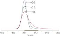
Figure 2: Exponentially modified Gaussian (EMG) peak model. Three peaks with increasing tailing and identical areas and retention times (peak apex). (a) Symmetrical Gaussian peak with Ï = 4.0 and Ï = 0.0, the same as in Figure 1; (b) same as peak 1 with Ï = 4.0; (c) same as peak 1 with Ï = 8.0.
Figure 2 illustrates the effect on a Gaussian peak of imposing increasingly strong peak tailing. The degree of peak tailing is determined by an exponential decay factor τ, sometimes referred to as the exponential time constant, using an exponentially modified Gaussian peak mathematical model.2 Figure 2(a) shows a purely Gaussian peak, Figure 2(b) shows the effect of an exponential decay factor τ equal to the peak's standard deviation σ, and Figure 2(c) shows an exponential decay factor of twice the standard deviation. From experience, most gas chromatographers would agree that peaks which lie between the purely symmetrical shape of Figure 2(a), where the asymmetry factor As = 1.0, and the slightly tailing shape of Figure 2(b), where As = 1.4, would be acceptable, while the more strongly tailing peak of Figure 2(c), where As = 2.1, might be considered as exhibiting excessive tailing. Table 1 lists measurements of the widths and asymmetry factors for these three peaks. In particular, it is significant that the ratio of the peaks' widths at base to the widths at half-height are roughly constant. This implies that we can apply the alternative version of the resolution equation given in equation 2 for determining the resolution of slightly to moderately tailing peaks, with asymmetry factors ranging from 1.0 to 2.0. The measurement of single peak asymmetry and the effects of asymmetry on peak area determination were discussed in two previous "GC Connections" columns.3,4 Now let's consider the effects of peak tailing on the resolution of a pair of peaks with the characteristics of the peak shown in Figure 2(b).

Table 1: Peak measurements from Figure 2. Measurement of As is at 10% of peak height.2
Resolution of Tailing Peaks
The resolution of a pair of peaks is defined in terms of their separation and widths. Peak tailing increases the widths of affected peaks, so to maintain a proscribed resolution level, the separation between a pair of peaks must increase in proportion to the amount of peak tailing. In the previous "GC Connections" instalment the characteristics of a pair of symmetrical peaks were measured at Rs = 1.0, 1.5 and 2.0. The symmetrical peak retention time data is given here in the first part of Table 2 and the peak overlap data is given in the first part of Table 3. These symmetrical peaks have the peak shape from Figure 2(a).

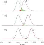
Figure 3: Resolution and overlap of tailing peaks. Peak shapes as in Figure 2(b). (a) Resolution = 1.0; (b) resolution = 1.5; (c) resolution = 2.0.
For comparison, the second parts of Tables 2 and 3 show how far apart the asymmetrical peaks must stand to achieve the stated resolution, and to what degree the peaks overlap when a moderate degree of tailing, with As = 1.4, is applied to both peaks by using the peak shape from Figure 2(b). Looking first at Table 2 for the retention data, an increase in the second peak's retention time of 4–7 s is required, depending upon the selected resolution level, to maintain the same resolution as peak tailing increases. Thus, considering only the resolution measurement for the moment, it is evident that when designing a robust chromatographic method that anticipates a certain degree of peak tailing, the degree of separation of the peaks must be significantly greater than would be required by accommodating only nontailing peaks.

Table 2: Retention times to attain specified resolution for equal-size peaks. The symmetrical peaks are those shown in Figure 2(a), and the tailing peaks are those shown in Figure 2(b). The data on symmetrical peaks are from the first part of this series.1 (a), (b) and (c) refer to the parts of Figure 3.
But now consider the meaning of peak resolution. It is tied directly to the degree of overlap of a pair of peaks. The goal is to provide an acceptable tradeoff between area measurement inaccuracies and the degree of separation. The expectations set by the overlap of symmetrical peaks are listed in the first part of Table 3. Here we can see that the overlap of a pair of symmetrical peaks with resolution of 1.5 is about 0.14%. This low overlap is the desired result of separating peaks at baseline resolution. It is the basis for the familiar guideline that baseline resolution allows for adequately accurate area measurements.

Table 3: Peak area measurements from Figure 3. Overlap is the percentage of the area of one peak that extends into the other. The data on symmetrical peaks are from the first part of this series.1 The peaks all have the same area. (a), (b) and (c) refer to the parts of Figure 3.
When peaks start to tail, however, this assumption breaks down. The first peak in the pair of tailing peaks under consideration, when separated sufficiently to produce a measured resolution of 1.5, extends into the second peak with an area that is 7.6 × greater than is obtained for the pair of symmetrical peaks at the same resolution. At a resolution of 2.0, the overlap area of the first asymmetrical peak into the second is about equal to the degree of overlap for the pair of symmetrical peaks at a resolution of 1.5. Thus, the degree of peak tailing has a direct effect on the meaning of baseline resolution. Higher resolution is required for tailing peaks to achieve the same degree of area overlap as nontailing peaks.
For the development of robust methods, a good guideline is to require the initial resolution of critical peak pairs to be at least 2.0, and preferably higher. Then, as peaks start to tail while columns age or inlets become contaminated with use, there will still be sufficient resolution available to achieve an acceptable separation. Providing a somewhat higher resolution also grants some leeway for drifting retention times due to ageing, and it facilitates the acceptability of new columns over the lifetime of a method as column manufacturer's normal variabilities come into play.
Conclusion
This instalment of "GC Connections" characterized the behaviour of symmetrical and nonsymmetrical peaks in terms of the effects of peak tailing on measured resolution and area overlap between peak pairs. For the moderately tailing peaks examined, greater differences in retention time are required to achieve a given resolution compared to symmetrical peaks, as might be expected. But the degree of overlap from the first peak into the second peak is greater for tailing peaks than for symmetrical peaks at the same resolution level, so additional resolution is required to achieve baseline separation of tailing peaks. The next installment will examine the effects that peak tailing has on measured areas and will take a look at some metrics other than resolution for characterization of the quality or degree of separations.
"GC Connections" editor John V. Hinshaw is a senior research scientist at Serveron Corp., Hillsboro, Oregon, and a member of LCGC Europe's editorial advisory board. Direct correspondence about this column should be sent to Alasdair Matheson, editor, LCGC Europe, Advanstar Communications, Poplar House, Park West, Sealand Road, Chester CH1 4RN, UK or e-mail: amatheson@advanstar.com
References
1. J.V. Hinshaw, LCGC North America, 28(7), 524–529 (2010).
2. A. Felinger, Data Analysis and Signal Processing in Chromatography (Elsevier, Amsterdam, The Netherlands, 1998).
3. J.V. Hinshaw, LCGC North America, 27(3), 232–245 (2009).
4. J.V. Hinshaw, LCGC North America, 27(7), 542–549 (2009).

New Study Reviews Chromatography Methods for Flavonoid Analysis
April 21st 2025Flavonoids are widely used metabolites that carry out various functions in different industries, such as food and cosmetics. Detecting, separating, and quantifying them in fruit species can be a complicated process.
University of Rouen-Normandy Scientists Explore Eco-Friendly Sampling Approach for GC-HRMS
April 17th 2025Root exudates—substances secreted by living plant roots—are challenging to sample, as they are typically extracted using artificial devices and can vary widely in both quantity and composition across plant species.

.png&w=3840&q=75)

.png&w=3840&q=75)


.png&w=3840&q=75)


.png&w=3840&q=75)


