Developments in HPLC Column Technology (2006–2008)
In the leadoff article, columnist Ron Majors provides an overview of column developments. He looks at various alternatives to high-throughput separations including small porous particles, monoliths and superficially-porous particles. Microfluidics and parallel column systems provide further alternatives. An alternative approach to isocratic method development uses optimized stationary phase combinations. Brief coverage of new phases for hydrophilic interaction chromatography, high temperature operation, chiral and mixed mode columns and finally supercritical fluid chromatography columns round out the overview. At the conclusion, Majors speculates on future directions in column technology.
In the leadoff article, columnist Ron Majors provides an overview of column developments. He looks at various alternatives to high-throughput separations including small porous particles, monoliths and superficially-porous particles. Microfluidics and parallel column systems provide further alternatives. An alternative approach to isocratic method development uses optimized stationary phase combinations. Brief coverage of new phases for hydrophilic interaction chromatography, high temperature operation, chiral and mixed mode columns and finally supercritical fluid chromatography columns round out the overview. At the conclusion, Majors speculates on future directions in column technology.
Since my article on the developments in high performance liquid chromatography (HPLC) column packing design (1) in the last supplement published just before HPLC 2006 (2), there has been a continuing interest in column developments with improvements in small, porous particle technology, monoliths (especially silica-based), superficially porous particles, and increased use of high-temperature LC with new phases capable of operating up to 200 °C. For handling complex samples, there has been a renewed interest in multidimensional and comprehensive LC×LC. In this update on column technology, I will cover some of the packing and column developments and highlight observations made in the past two years and speculate in future directions in column technology.

Elsewhere in this special supplement other column topics will expand on changes that have occurred in stationary phases and in multidimensional separations.
Further Developments in Small Porous Packings
One of the driving forces for continued improvements in HPLC column technology is the requirement for higher throughput but without sacrificing analytical performance. One of the trends noted in the last two years is the strong interest in smaller particles, especially those with average particle diameters less than 2 μm. In 2006, only a few companies were promoting the virtues of sub-2-μm columns (1). Since further introductions at Pittcon 2008 (3), there are 14 companies that have commercialized these small particles (Table I). When sub-2-μm particles are packed into short columns, separations can be performed faster, sometimes in just a minute or two, than longer columns packed with larger particles without sacrificing chromatographic resolution. The flat van Deemter curves noted for the sub-2-μm columns allow relatively high flow rates to be used, in the range of 2–3 mL/min if necessary. Even though the column pressure increases with the inverse square of the average particle diameter, these shorter columns (usually 50 mm and under) can be used with most conventional HPLC pumping systems, even at these increased flow rates.
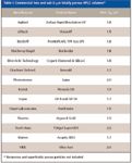
Table I: Commercial two and sub-2-mm totally porous HPLC columns*
For more demanding separations, longer columns of 100- and 150-mm lengths may be required. With such lengths, column back pressure may increase beyond the capabilities of conventional pumping systems (~400 bar upper limit). Thus, in recent years, pumping systems capable of operation up to 20,000 psi (1330 bar) have come onto the market. However, it is rare to see a separation run at such high pressures, even at 1000 bar. User concerns about stress on instrument hardware and on the columns themselves have limited widespread applications at these high pressures. The demands of sample cleanliness and easier "pluggability" of the small porosity frits terminating the sub-2-μm columns also have made some users cautious into jumping into their routine application. Nevertheless, these columns have proven to be rugged if used properly by ensuring particle-free samples are injected. With the coming of low-dead-volume, high-pressure guard columns to help to protect the analytical column, liquid chromatographers should become more comfortable using these columns.
Even so, some column and instrument suppliers have "backed-off" in joining the sub-2-μm bandwagon and have made more moderate reduction in the particle size from the popular 3–3.5 μm columns (see Table II). Since for packed columns in the range of 2–3 μm, the particle diameter is larger than the sub-2-μm particles, the pressure drop is lower but efficiency is better than the more popular 3–3.5 μm particles. The arguments for using packings in the 2–3 μm range evolve around considering the entire separation cycle time where higher temperatures are used to improve efficiency and lower back pressure, improved liquid chromatograph hydraulics to lower band dispersion and gradient reequilibration time, and faster autosamplers, detectors and data systems. The use of lower pressures also places less stress on the instrumentation (for example, pump seals, pistons, check valves, and injector valve cores) and on column materials.
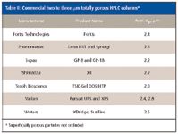
Table II: Commercial two to three mm totally porous HPLC columns*
So, it should be interesting to see if even smaller porous particles will be in vogue in the next two years. Currently, the smallest particle size that is commercially available is 1.5 μm. The pressure "race" seems to be on in HPLC instrumentation so there is no reason to believe that the instruments could not keep up with further reductions in particle size. However, there are other competing technologies that do not expose the column and instrumentation to such dramatic pressure conditions: monoliths and superficially porous packed columns.
Monolithic Columns
Monoliths have been around for a decade or more. Polymeric monoliths were first described back in the 1960s but the first successful ones designed for protein separations were much later in the late 1980s (4). Commercial products have become widely available, mainly useful for larger biomolecules. Polymeric monoliths are reviewed by Svec and Krenkova (5) elsewhere in this supplement. Silica-based monoliths came later with the pivotal work by Tanaka and Nakanishi and coworkers (6) and were commercialized by Merck KGaA (Darmstadt, Germany) who licensed the patents from the Kyoto Institute of Technology (Kyoto, Japan). Tanaka and his research group have continued to study silica monoliths and have gained a better understanding of the physical and chemical properties. In addition, in addition to reversed-phase ligands they have modified these monoliths with various chemistries such as ion exchange, hydrophilic interaction, chiral, and mixed modes (7). Because of their small-sized skeletons and wide through-pores much higher efficiency can be achieved than the case of particle-packed columns at a similar pressure drop. Alternatively, commercial silica monolithic columns have achieved efficiencies equivalent to a 4-μm silica column but with a pressure drop around 40–45% of the packed column run under the same linear velocity. The downside is that the longest length of commercial silica monolith is 100 mm but they can be connected in series to achieve higher plate numbers.
Recently, the Chromolith FastGradient 50 mm × 2 mm column by Merck KGaA was introduced. Although commercial silica-based monoliths have been available for nearly a decade, the 4.6-mm i.d. columns required too high of a flow rate (3–5 mL/min) to get reasonable separation times and certainly flow was too high for interfacing to a mass spectrometer. The problem was that the silica rod monoliths are first synthesized outside of the column. As the silica goes through the polymerization and drying process, the rod shrinks in its diameter and length. Merck scientists made a breakthrough a half dozen years ago and were able to encapsulate the silica rod with PEEK polymer, making a tight fit around the silica rod and thereby negating wall effects. Up until now, the smallest diameter of silica rods was 3.0-mm which required flow rates still too high for electrospray ionization mass spectrometry (ESI–MS); the silica monoliths were still somewhat shunned by mass spectroscopists. Now, the Merck scientists were able to make silica rods with the proper initial dimensions to shrink to 2.0-mm outer diameter to be successfully encapsulated. Both Merck and Phenomenex (Torrance, California), who licenses the Merck monolith technology, introduced 50 mm × 2 mm silica monoliths at Pittcon 2008. Now LC–MS users will have a column that can more easily be interfaced to their "detector." In addition, the new 2.0-mm configuration also will save solvent for conventional LC–UV users. Of course, the biggest advantage of the monolith technology is the lower pressure drop compared with particulate-based columns of the same performance level. Currently, only a 50-mm length of the 2-mm i.d. Chromolith is available but longer columns can be coupled if high plate counts are required. Recent developments on commercial monolith columns are covered elsewhere in this supplement (8).
Superficially Porous Particle Packed Columns
The concept of superficially porous particles has been around since the beginnings of HPLC. Basically, this type of particle has a solid inner core and a porous outer layer. Compared with a totally porous particle, the limited diffusion path length into and out of the outer porous layer allows faster separations to occur because migration time within the stationary phase is decreased. I have recently summarized these developments (9) and will not repeat the historical developments here. Eventually, for general HPLC of small molecules, porous microparticles won out over the superficially porous concept but it has reappeared occasionally to address alternate solutions to specific problems. First was the development of Poroshell 300 (Agilent Technologies, Santa Clara, California) by Kirkland (10). High-speed reversed-phase chromatographic separation of proteins using typical 5-μm wide pore (300 Å) porous particles is difficult because of their low diffusion coefficients. At high flow rates there is considerable band broadening. With the superficially porous concept using a wide pore porous layer (0.25-μm thick), the diffusion distance is limited and with increased flow rates, band broadening was reduced.
Second, more recently, the concept was revisited as a response to the pressure drop experienced by sub-2-μm particles. The superficially porous particle, also called a fused-core particle, has a diameter of 2.7 μm but with a porous layer of 0.5 μm and 90-Å pores, more suited to small molecules. The larger diameter particle provides a lower pressure drop than smaller particles yet the short diffusion path length gave rapid mass transfer indicative of a sub-2-μm porous particle. Figure 1 represents a typical application of a superficially porous particle column using the hydrophilic interaction chromatography (HILIC) mode with a polar stationary phase and a nonpolar mobile phase containing some water. The HILIC mode is particularly useful for the separation of very polar analytes only slightly retained on a typical reversed-phase HPLC column. In Figure 1, the water-soluble compounds, adenosine, a nucleoside, and cytosine, a nucleobase, are eluted very quickly from the reversed-phase column (bottom chromatogram) and are unresolved. The nonpolar acenaphthene is retained as would be expected. Using HILIC (top chromatogram), the polar compounds are now well retained and even separated while the acenaphthene is now unretained. In HILIC, elution order is frequently reversed when compared with the reversed-phase mode. The basics of HILIC is covered elsewhere in this supplement by author David McCalley (12).
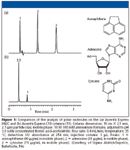
Figure 1
Alternative High-Throughput Chromatographic Techniques
For users who are faced with increasing sample loads, the previous approaches to increasing speed are based upon more conventional approaches. Two areas that address the throughput issue are microfluidics and parallel processing. Microfluidics deals with the miniaturization of chromatographic and electrophoretic techniques. There are many advantages of reducing the size of the experiment such as the analysis of smaller samples with increased sensitivity, solvent savings and reduction of chemical waste, potential smaller instrument footprint, ability for direct interfacing to MS, and simpler automation. The capability to use microfluidics with parallel processing allows the simultaneous analysis of multiple samples in a single instrument. Nanostream (Pasadena, California) has developed a Brio cartridge system (Figure 2) where a plastic cartridge somewhat larger than a CD case contains 24 parallel separation lanes with detection channels. This microfluidic device snaps into the company's Nanostream CL separations instrument and can generate separations every 12 s. The system is designed to compete with both traditional microassay systems and high-throughput HPLC systems. Various column packings are available depending upon the needs of the assay.
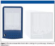
Figure 2
Parallel analytical and preparative HPLC systems from Sepiatec (Berlin, Germany) allow eight samples to be processed simultaneously to increase sample throughput with resultant cost savings and reduction in bench space. Their Sepmatix parallel HPLC system with a single pump uses a flow controller to control and spread the flow of solvent using an active splitter module. The autosampler is able to inject eight samples in parallel and one multiplexed photodiode-array detector performs detection. An oven that controls the temperature of each column from 5 °C to 70 °C is available.
The Eksigent (Dublin, California) ExpressLC 800 parallel HPLC system also consists of eight independent channels of 300-μm capillary columns, independent mobile phases, gradients, injectors, and diode-array detectors with 45-nL cell volume. The system volume is only 300 μL. The flow rates delivered by 16 micro-pumps with microfluidic flow control can be varied from 1 to 30 μL/min, optimized for the Chrom XP 300-μm columns with lengths of 3–15 cm.
The latter parallel systems can be used for column and mobile phase scouting where multiple columns with different stationary phases can be used simultaneously and solvent selector valves can select various combinations of solvents to optimize retention and selectivity. One popular application would be for chiral column screening. For the most part, chiral separations are a matter of trial and error although chiral column manufacturers are providing more "universal" columns that have decreased the number of columns that must be screened.
Column Configurations for Isocratic Method Development
The optimization of a separation becomes much easier once the optimal stationary phase has been found. Phase Optimized Liquid Chromatography (POPLC) (Bischoff, Leonberg, Germany) uses a new approach in method development and optimization. After a rough first choice of mobile phase, only the stationary phase needs to be optimized. Based upon a model previously used to optimize mobile phases in LC (13), a combination of stationary phases using a segmented column system is used. The segmented columns system consists of easily joined columns of different lengths and different stationary phases.
First retention times are determined with isocratic chromatographic runs of the sample analytes on different stationary phases using the same mobile phase, chosen by experience or trial. The stationary phases used for these basic measurements should be of different selectivities. For example, C18, C18 with enhanced polar selectivity and phenyl, C30, or cyanopropyl could be used for this purpose. The retention of the analytes on these phases may be different, due to different mechanisms of interaction. The individual retention times are then used for calculations performed by optimization software. The software calculates the optimum combination of column segments for best resolution in the shortest time.
An example of using this approach is depicted in Figure 3 where a separation of eight triazine pesticides was performed isocratically on four different stationary phases (22). As shown in Figure 3a, any individual phase did not separate all eight pesticides. After importing this data and entering the separation criteria (for example, maximum separation time, optimum selectivity) into the optimizer software, the top chromatogram in Figure 3b was the optimum separation that was proposed by joining three different column segments is series as shown on Figure 3b. In the bottom chromatogram of Figure 3b was the actual separation performed in the laboratory under the optimized isocratic conditions.
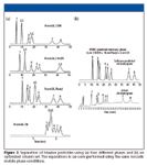
Figure 3
Highlights of New Phase Introductions
HILIC: In the last two years, a large number of specialty column introductions at the Pittsburgh Conferences (14,15) for the HILIC mode. HILIC is a separation technique for highly polar analytes that gets around some of the problems associated with reversed-phase chromatography such as low retention or phase collapse (dewetting). HILIC uses a polar stationary phase such as bare silica gel, polar bonded phase (for example, diol), and certain mixed mode or zwitterionic phases (see Table III). Operating conditions usually requires a high percentage of a nonpolar mobile phase, similar to the requirements for normal-phase chromatography. However, unlike normal-phase chromatography, which uses nonpolar solvents such as hexane and methylene chloride and tries to exclude water from the mobile phase, HILIC requires some water in the mobile phase to maintain a stagnant enriched water layer on the packing surface into which analytes may selectively partition. In addition, water-miscible organic solvents are used. Under HILIC, polar analytes are well retained and are eluted in order of increasing hydrophilicity. HILIC is especially favored by mass spectroscopists since ionization efficiency is often enhanced in organic solvents and the presence of low or no buffer salt compared with reversed-phase chromatography. In our last HPLC column survey in the United States, HILIC rose from practically nothing to achieve a 4% usage factor so many chromatographers are discovering this useful mode when reversed-phase HPLC does not quite do the job. Note that it is sometimes referred to as the aqueous normal phase mode so do not let that nomenclature confuse you.
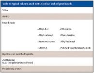
Table III: Typical columns used in HILIC (silica- and polymer-based)
High-temperature phases: With the increased interest in the use of high column temperatures in HPLC, a number of phases have been developed (or at least emphasized) for their high-temperature stability. The use of increased temperature has some big advantages: speed, increased efficiency, lower consumption of organic solvent, improved detectability, improved peak shape, and decreased pressure drop. The last feature is particularly interesting since the increased use of the sub-2-μm columns with resultant higher operating pressures. Pressure can be lowered by factors of 2–3 when increasing the column temperature to 100 °C. Of course, there is some concern about analyte stability but this has more or less been alleviated by some careful studies on this subject (16–18).
Another concern is the stability of phase materials at high temperature. Table IV gives a sampling of commercially available LC columns for high-temperature operation. Silica-based bonded phase columns have problems at high temperature due to loss of bonded phase from the silica support at high temperatures (18), and loss is exacerbated at higher pH values. Most monomeric bonded silica phases are stable to 60 °C and care should be exercised in taking them to much higher temperatures. Some special silica-based phases covered in Table II will operate at extended ranges. The most stable phases are nonsilica phases such as graphitized carbon, zirconia, and polymeric phases such as polystyrene–divinylbenzene. However, some of these phases give poorer efficiency or have to be used with restricted buffer conditions.

Table IV: A sampling of commercial columns for high temperature LC*
A third issue with high temperature operation is termed "thermal mismatch." Thermal mismatch is the difference in temperature between the column and the mobile phase that produces a temperature gradient across the column radius. Thermal mismatch can cause band spreading, poor peak shape, and split peaks. Thermal mismatch can occur at the column inlet by a cooler mobile phase coming into the column or at the column exit where the hot solvent must be cooled down to flow through a detector cell operating at room temperature. In addition, in the detector cell, the hot solvent must remain a liquid so that there is no bubble formation due to boiling solvent. I won't elaborate here on this subject since Yang (19) has done a nice job of addressing the issue of thermal mismatch.
Chiral: In the past year, the emergence of the immobilized (bonded) polysaccharide chiral phases has allowed the use of a wider range of solvents so that fewer chiral phases are needed to cover the wide range of enantiomeric compounds. The Chiralpak IA and IB (Chiral Technologies, West Chester, Pennsylvania) are immobilized versions of the Chiralpak AD and Chiracel OD, respectively, while CHIRALPAK IC has a unique chiral selector, based upon the 3,5-dichlorophenylcarbamate of cellulose, immobilized on 5-μm silica. In addition, since coated polysaccharide patents are coming to an end, a number of companies have entered the market for these popular phases (3).
An interesting approach to chiral chromatography was the introduction of Zirchrom Chiral phases in 2006 (3). These zirconia-based columns have strong Lewis acid sites that anchor (chemisorb) the chiral selector. The chiral selector can be removed by alkaline treatment (pH > 12) to regenerate a contaminated or spent column or to convert the column into another chiral phase by rinsing with chiral selector solution. Currently, ZirChrom offers six chiral columns in the ZirChrom-Chiral line: (R) and (S)-3,5-dinitrobenzoyl-leucine), (R) and (S)-3,5-dinitrobenzoyl-phenylglycine), and anchor modified 3,5-dimethylphenyl-carbamoyl cellulose) and an (S)-3,5-nitrobenzoyl-leucine. They are said to be developing a single zirconia column plus a kit of pure chiral selector coating reagents that will allow users to easily remove and replace chiral selectors. Chiral selectors with multiple chiral centers, featuring both pi-donor and acceptor groups, also are under development, as are chiral selectors based upon polysaccharides. For a complete review of new chiral columns, refer to the paper by Beesley (21).
Supercritical fluid chromatography (SFC): Now that SFC has found a niche in the purification of chiral and other pharmaceuticals, a wide range of HPLC-like columns are now being offered by various companies. The technique is very "green" because the main component of the mobile phase is carbon dioxide which reverts to its gaseous state when the supercritical conditions are no longer present at the detector outlet. Only small amounts of modifier are needed to impart some polarity to the mobile phase so that more polar pharmaceuticals can be handled by SFC. Most of the SFC phases offered commercially are polar phases since the carbon dioxide–containing phases are fairly nonpolar, much like normal-phase chromatography. Typical phases used in SFC are silica, nitroaromatic, amino phenyl, ethyl pyridine, cyano, amino, strong cation exchange, and diol. The SFC columns have the same dimensions as HPLC columns so it is not a stretch for companies to enter this market.
Mixed-mode HPLC columns: Most liquid chromatographers choose a C18 or C8 phase as their first choice for a reversed-phase chromatographic stationary phase. Sometimes the resulting separation is actually a mixed mechanism since hydrophobic interactions may occur between the organic portion of the analytes while the polar portion of the analyte interacts with residual silanol groups. This mixed mechanism is not necessarily bad but sometimes the ratio of bonded phase to unreacted silanols is not well controlled; under these conditions, selectivity and retention may be different from column to column. However, it has become popular in recent years to actually incorporate another functional group into the alkyl phases that will allow additional interaction with polar functional groups and impart a different selectivity than a straight alkyl phase. These mixed-mode columns have become attractive in the pharmaceutical industry where many drugs contain polar functionality that will interact with the polar functional group. One common example would be the incorporation of a carbamate or amide functional group, the so-called polar embedded phases which work well with basic compounds and also prevent phase collapse (dewetting) when the amount of organic solvent in the mobile phase decreases. Some typical functional groups in mixed-mode bonded phases are C8/SCX, C18/SAX, hydride/COOH, C18/OH, and phenyl/quaternary amine.
Future Directions in HPLC Column Technology
Although silica gel and silica hybrids with chemically bonded phases still dominate the applications of HPLC, newer packing materials continue to be developed. Smaller particle sizes of these conventional phases seemed to have caught on with more and more companies now joining the bandwagon of sub-2-μm particles. Whether the particle size reduction trend continues is a matter of speculation. Smaller particles will require even higher pressure and place additional constraints on the packing materials, column hardware especially frit design, instrument consumable parts such as pistons, check valves, and seals as well as increased attention to extracolumn effects and gradient delay (dwell volumes). For those needing high resolution who want to use these smaller particles, the use of longer columns will place even more restrictions on the chromatography. Of course another way to tackle the high resolution problem is to employ multidimensional and comprehensive LC×LC techniques. However, until an easy-to-use, commercial system is available most users are not going to gravitate towards this more complex methodology. Will the alternative of compromising on 2–3 μm particles satisfy user needs to get better separations than the 3–3.5 μm totally porous particles with lower pressure drop than the sub-2-μm columns? Probably for those who do not need the ultimate in speed the answer is "yes" but eventually their needs may drive them to consider further alternatives. Not everybody needs 1- or 2-min separations.
The alternative ideas of using silica monoliths and superficially porous particles for small molecule analytical separations could swing the pendulum away from even smaller porous particles (<1.5 μm). Both of these approaches provide separations with good-to-excellent efficiencies but at much lower pressure drops. Work going on in academia (7) in optimizing the silica skeletons of monoliths to improve the overall efficiency without throwing away a main advantage of decreased pressure drop, may result in monoliths capable of generating even more plates. The new 2.0-mm i.d. commercial monoliths should now be used more by the LC–MS community but eventually they will want to tackle more difficult separations than a 50-mm column can handle. Although joining the low-pressure drop monolith columns in series sounds attractive, the loss of plates in the column connections and the increased cost for multiple monolith columns will discourage many from going this route. The superficially porous particles provide increased efficiency over the monoliths and with the thick superficially porous layer, the sample capacity is not that much lower than a totally porous particle. The increased availability of these superficially porous particles should introduce this technology to a wider audience.
The idea of open tubular columns as the ultimate has been around for almost as long as liquid chromatography has been around and some interesting work on 10-μm i.d. capillaries has even been published albeit with a porous layer film on the inner walls of the capillary. In-situ synthesized polystyrene–divinylbenzene monoliths in 20-μm capillaries also have proven useful for peptide fragment separations (23) but such columns and accompanying instrumentation are still a long way off. From a commercial standpoint, the area of nanoLC and microfluidic separation techniques has received some attention especially for proteomics applications but biochemists using 2D gel techniques have not quite mastered 2D chromatographic techniques yet.
As far as mode usage, reversed-phase chromatography will continue to dominate applications and column introductions at Pittcon (15) as it has in the past two decades. With the wider availability of HILIC/aqueous reversed-phase columns, this technique should receive more attention from users who have faced the analysis of polar analytes unretained or poorly retained by regular reversed-phase columns and do not want to turn to either ion-pair chromatography or normal-phase chromatography, with all of their gradient equilibration problems. The advent of the popular polysaccharide bonded chiral phases will give chiral chromatographers the ability to use fewer chiral columns to screen their next chiral drug since they can be used with more solvent systems without fear of stripping the expensive phase.
References
(1) R.E. Majors, LCGC 24(S4), 8–15 (2006).
(2) LCGC 24(S4) (2006).
(3) R.E. Majors, LCGC 26(3) (2008).
(4) T.B. Tennikova, F. Svec, and B.G. Belenkii, J. Liquid Chromatogr.13, 63 (1990).
(5) F. Svec and J. Krenkova, LCGC 26(S4) (2008).
(6) N. Tanaka, N. Ishizuka, K. Hosoya, K. Kimata, H. Minakuchi, K. Nakanishi, and N. Soga, Kuromatogurafi 14, 50–51 (1993).
(7) O. Nunez, K. Nakanishi, and N. Tanaka, J. Chromatogr. A, in press.
(8) K. Cabrera, LCGC 26(S4) (2008).
(9) R.E. Majors, LCGC 26(1) (2008).
(10) J.J. Kirkland, Anal. Chem.64, 1239–1245 (1992).
(11) Ascentis Express HILIC HPLC Columns, Sigma-Aldrich.com, Supelco Analytical, 2008.
(12) D. McCalley, LCGC 26(S4) (2008).
(13) S. Nyiredy, K. Dallenbach-Tölke, and O. Sticher in J. Planar Chromatogr.1, 1241 (1988).
(14) R.E. Majors, LCGC 25(1) (2007).
(15) J. Clark, Today's Chemist at Work 13 (8), 43–45 (2004).
(16) B. Yan et al., J. Sep. Sci. 30, 1672 (2007).
(17) J.D. Thompson and P.W. Carr, Anal. Chem.74, 1017–1023 (2002).
(18) Y. Yang, LCGC 26(S4) (2008).
(19) G. Van Hoenacker and P. Sandra, Anal. Bioanal. Chem. 390, 245–248 (2008).
(20) T. Beesley, LCGC 26(S4) (2008).
(21) MacMod Analytical and Bischoff Chromatography, "Phase Optimization: A New Approach to HPLC Method Development", The Application Notebook, LCGC North America, September, 2007, pp. 72–75.
(22) J. Zhang, S.-L. Wu, J. Kim, and B.L. Karger, J. Chromatgr., A, 295–307 (2007).

New Method Explored for the Detection of CECs in Crops Irrigated with Contaminated Water
April 30th 2025This new study presents a validated QuEChERS–LC-MS/MS method for detecting eight persistent, mobile, and toxic substances in escarole, tomatoes, and tomato leaves irrigated with contaminated water.

.png&w=3840&q=75)

.png&w=3840&q=75)


.png&w=3840&q=75)


.png&w=3840&q=75)


