How Can We Run a Gas Chromatograph from Anywhere?
Computers control all aspects of modern GC instrument operation, from temperature to valve actuation. We look under the hood to see how this works.
This installment of “GC Connections” is a follow up to September’s column “From Detector to Decision: How Does the GC Instrument Generate Your Data?” This time, we explore the other side of the instrument-data system relationship—how the data system controls the functions of the instrument. Drawing on classical electronics and instrument designs, we see the evolution of instrument controls from knobs and gauges on the front panel of the instrument to computer control and finally to today’s web-based systems that allow instrument control and monitoring from anywhere. We see that the same fundamental electronic principles used to manually control gas chromatographs in the 1970s are still at the center of today’s modern electronically controlled systems.
In our previous column, we explained that the controls for today’s gas chromatographs include an on-board computer that provides the low voltage signals that actuate and direct analog devices that control functions such as starting, stopping, and data collecting (1). Taking this idea one step further, we see that this computer controls all aspects of instrument operation, including temperature and flow control and valve or switch actuation. As seen in the September column, the basic controls (valves opening and closing, heaters heating, and switches moving) for data collection and analysis are still analog operations that are performed by mechanical devices even though these devices have been miniaturized. Digital control of these analog devices is what allows a gas chromatograph (GC) instrument to be operated from an external data system or even from off-site as long as the requisite software and networking are available.
Figure 1 shows the flow of data or instructions between an external control system and an electronic component on a GC instrument, such as the inlet heater. As the user, you want to instruct the instrument to heat the inlet to 250 oC. First, you enter the value into the data system (or on the front panel of the instrument if it has a keypad or touch screen). Second, the data system transfers the request to the instrument using one of the communication protocols (typically USB or ethernet) where the microprocessor on the instrument receives the signal and through its on-board software sends a low-voltage signal to a relay, which closes a mechanical switch to activate the heater. A second circuit within the inlet block includes a temperature sensor (usually a temperature-sensitive resistor) that provides a signal back to the on-board software when the desired temperature is reached so that the heater circuit can be opened (in other words, turned off).
FIGURE 1: Block diagram of the relationship between the user and a switch or valve on a modern GC instrument. Inside the blue box are the functions that are now on-board many GC instruments. Classical digital and analog electronics allow these functions to happen in the background.
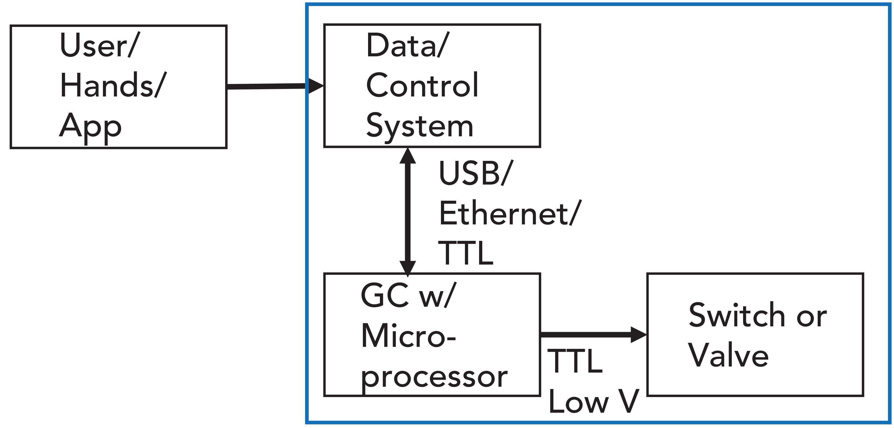
With digital electronics and software providing the interface between the operator and the device (in this case the inlet heater), we can see that, if the software can be operated through a data system separated from the GC instrument over a company intranet or over the internet, then the instrument can as well.
Even though software provides the user with convenient and powerful controls, the instrument itself still relies on mechanical devices to operate. Although these devices have been miniaturized, they still fundamentally perform the same tasks that the first GC instruments did. In our previous installment, we discussed the basic principles of digital and analog electronics in gas chromatographs. We saw that, although instrument control and data collection are now digital, the underlying chemistry that occurs at the detector to generate signals and the underlying mechanics that allow control of temperatures, gas flows, and instrument functions, are analog. We noted that analog and digital signals can be interconverted and that digital signals also provide the capability for instruments to have friendly and easy-to-use controls and user interfaces.
In this installment, we look more closely at the processes by which modern GC instruments are controlled on the front end, with functions such as starting and stopping, actuating valves, such as the split purge vent, controlling temperature zones, and gas flows. As we did in September, we see how these operations work in a modern GC instrument by look- ing back at some older systems in which these operations were performed manually or with mechanical controls.
All of the control functions on early GC instruments were manually operated, as seen in many pictures of early systems available on the Internet, such as a photograph of an F&M Scientific Model 700 dual column gas chromatograph of the early 1960s, available from the Science History Institute website (2). Several knobs and switches and gas outlet ports can be seen. Needle valves and manual regulators controlled the gas flows. The column oven was accessed from the top. Clearly, this instrument required the operator to be present to perform every function, including injecting the sample; there was no auto-sampler.
The several knobs on the front of this and other early and simple gas chromatographs provided the familiar temperature controls for the column oven, detector, and injector port. Additional knobs provided control functions for a thermal conductivity detector, including filament current, with coarse and fine adjustments and signal attenuation. A chart recorder (not shown) would have plotted the analog detector signal versus time on a roll of paper. Compared to today’s instruments, this system was also very bulky, had high power consumption, and required the user to be present for every analysis. Following the analysis, data processing was done by hand, with the chromatogram being printed out on a paper roll. Instrumental conditions were entered by hand directly on the paper or entered into a lab notebook.
The knobs for the temperature controllers are called potentiometers, which provide a convenient means for regulating the voltage by changing the resistance with constant current and applying Ohm’s Law, which states:
V = IR [1]
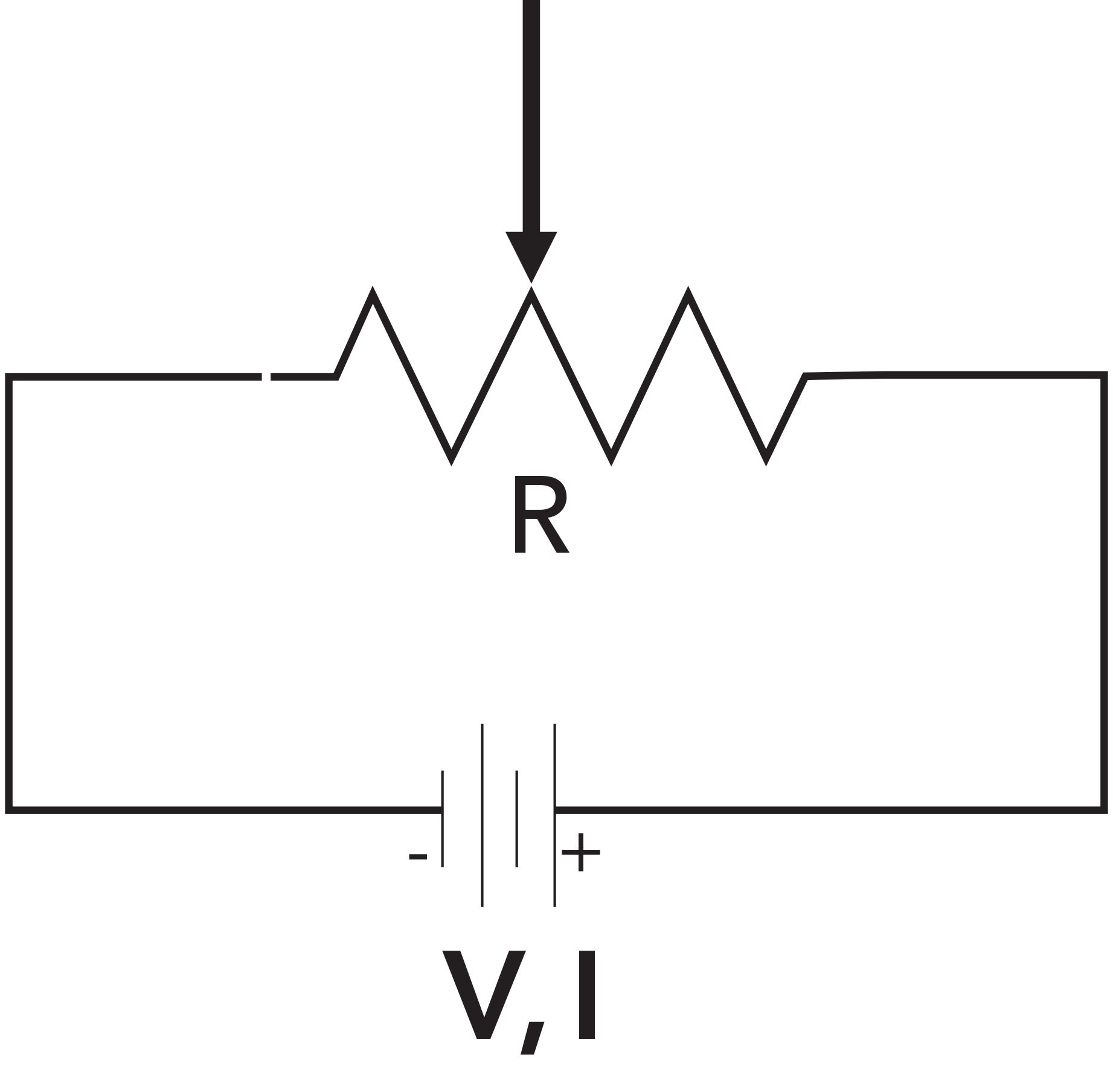
where V represents the voltage (V), I the current (A) and R the resistance (Ohms). A simplified circuit diagram of a potentiometer is shown in Figure 2. You can think of a potentiometer as performing the same function as the knobs on your electric stove or oven, providing variable resistance to the heating coils. At the point where the arrow connects to the resistor, the resistance changes and therefore the voltage. Dials, like those seen on the front of old GC instruments, are simply circular resistors that allow for changes in the resistance and therefore the voltage, as the knob is turned. In Figure 2, the arrow represents the dial, showing the variability of the resistance. One disadvantage of this kind of variable resistor is that the excess current must be dissipated as heat, so this function today is often performed using semiconductor-based devices that have much less heat dissipation and can be much smaller than knobs designed to be turned by hand.
FIGURE 2: Simplified circuit diagram showing a potentiometer. The power supply (V, I) is at the bottom. The variable resistor (R) is at the top, with the position of the arrow indicating the dial or slide that makes the resistance variable.
Even in today’s fully digital GC instruments, the digital controls, which are convenient for users to operate, are still operating analog devices. As examples, we will examine three of the important control functions on any gas chromatograph: the remote start–stop and valve actuators, the inlet (and detector) heaters, and the split vent (purge) valve. Although we now control these through the keypad, software, or an app, and even though the some of the devices themselves have been miniaturized, they still perform the same functions as on past instruments.
In September, we examined the remote-control port on a 1990s-era GC instrument and saw several control functions. Each of these functions works using a simple relay called a contact closure, essentially an electrically operated switch that can leave the circuit open (no current is flowing) or closed (current flows). The flowing current in a closed contact closure can direct the actuation of a switch or valve or perform other tasks. The contact closure is directed to open or close by the application of a small voltage to the switch.
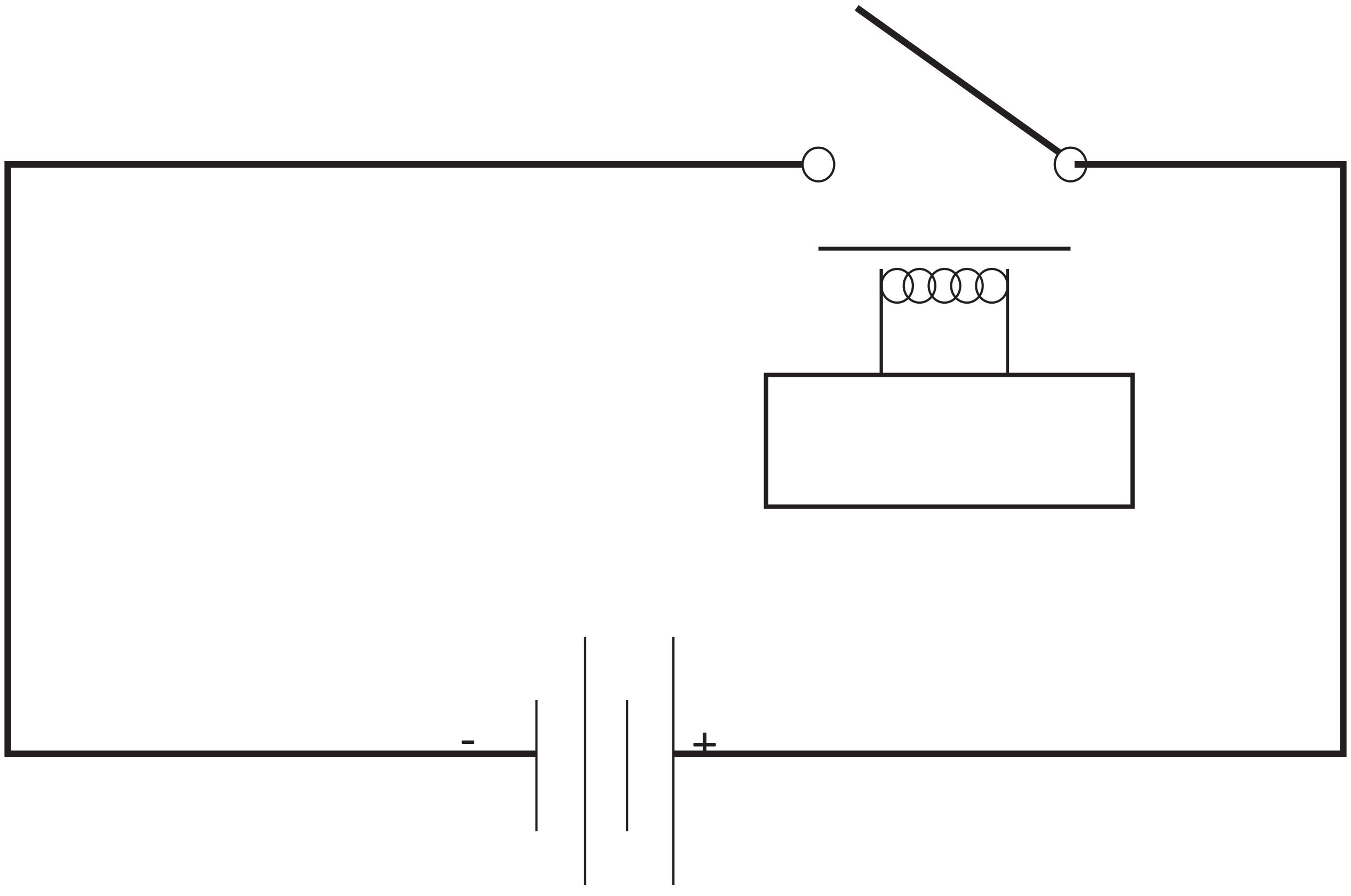
Figure 3 shows a simplified circuit diagram including a contact closure relay. A common relay for a single switch includes four contacts: Two are for the circuit being opened or closed, and the other two are for controlling the relay itself, as seen by the four leads shown in Figure 3. In the case of the start–stop function, when the GC instrument is not performing a run, the circuit is open (the switch is off). A low- voltage signal from a data system is sent to the relay, which mechanically closes the circuit, causing current to flow and start- ing the GC instrument. The relay is much like turning on the switch for a light bulb. When the instrument starts, the relay usually switches “on,” then resets quickly to the “off” position, generating a start “pulse” that instructs the instrument to begin the run. A similar relay instruction is then used at the end of the run for the GC instrument to signal to the data system and other devices that the run is over.
FIGURE 3: Circuit diagram for a simple relay with a contact closure. When the circuit is closed, the current flows. The closure is controlled by the relay in the middle, which receives a low-voltage signal from the controller.
The zone heaters are a second set of analog devices that are now controlled digitally. All gas chromatographs have three heated zones: the inlet, the column oven, and the detector. The inlet is heated to assist in vaporizing the injected sample, the column oven is heated to control the separation, and the detector is heated to keep it clean. Each of these heaters is a direct current device that operates according to Ohm’s Law and Joule heating, often called ohmic or resistive heating. The relationships between voltage (V), current (I), resistance (R), and heat (J) are given by:
V = IR and P αI2R, where P (watts) = J/s [2]
In short, heat is generated in a resistor proportionally to the square of the input current and proportionally to the resistance. The heaters in the oven, inlet, and detector are simple resistors to which current is applied to produce heat, much in the same way as the oven in your kitchen. On older GC instruments, these heaters were controlled using the potentiometers on the front of the instrument. On newer, digitally controlled GC instruments, the heaters are turned on and off by low voltage signals sent to relays, as described above and the temperature is monitored by a second circuit using a temperature-sensitive resistor.
Gas flow control valves are a third necessary control in a GC instrument. A typical solenoid valve classically used in split–splitless inlets to switch between split and splitless mode is shown in Figure 4. The fundamentals of split and splitless injection modes were discussed in a recent “GC Connections” installment (2). In short, the solenoid valve is used to redirect most of the carrier gas flow from the glass sleeve to the split purge vent during splitless operation, without changing the overall flow into the column.
FIGURE 4: Photograph of the electronic solenoid valve that controls the split vent purge on a 1990s-era GC instrument. Today’s solid-state units perform the same functions.
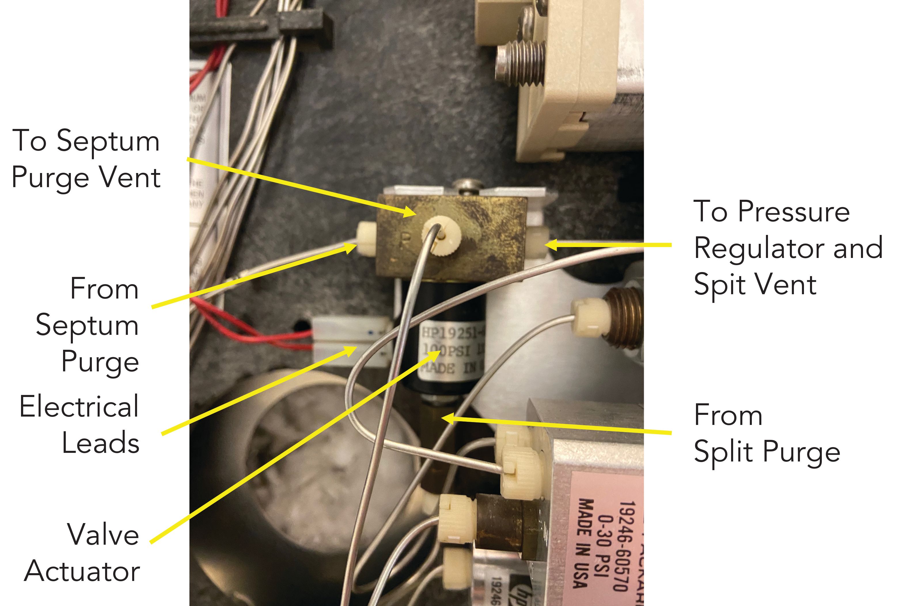
The valve is actuated by a simple contact closure that directs the valve to be either “open” in split mode or “closed” in splitless mode. When the valve is open in a split injection, flow enters through both the septum purge and split vent lines and exits to the septum purge vent and to the total flow controller and back pressure regulator ultimately to the split vent. When the valve is closed for a splitless injection, the split vent inlet line from the inlet is closed, forcing all of the flow to enter the valve through the septum purge line and still exit through both exit lines. With the inlet still pressurized this has the effect in the inlet of reducing the flow through the inlet liner for the splitless injection. With these older valves, an audible “click” could be heard whenever the valve was opened or closed. For many old-school chromatographers, this sound was routine and comforting.
Figure 4 shows several additional gas lines and wires seen in and around those for the split–spitless inlet, which serves as a second inlet in the pictured system. Today’s gas chromatographs include all of the pneumatic components and the associated electronics for operating the inlets in single pneumatic packs that can be easily inserted or removed from the main instrument. Although this provides easy installation and “plug and play” convenience, it comes at the cost that none of the components are user serviceable. In the 1990s, if the solenoid valve wore out (because it is mechanical; it eventually would), it was a simple and inexpensive matter to order a new one and replace it. If the solenoid valve equivalent or another single component in the pneumatic pack has to be replaced, the entire unit usually has to be replaced, often at a significant cost.
Within the GC instrument, all of these electronic components are controlled through the main board, which is shown in Figure 5. Most interesting to note is the Z-80 microprocessor for a 1990s vintage GC instrument, which was discussed in detail in our previous article (1). This simple 8-bit microprocessor developed in the 1970s still finds its use today in a variety of devices in the “Internet of things.”
FIGURE 5: Photograph of the motherboard on a 1990s-era GC instrument. Note that this is a fully functional computer in its own right.
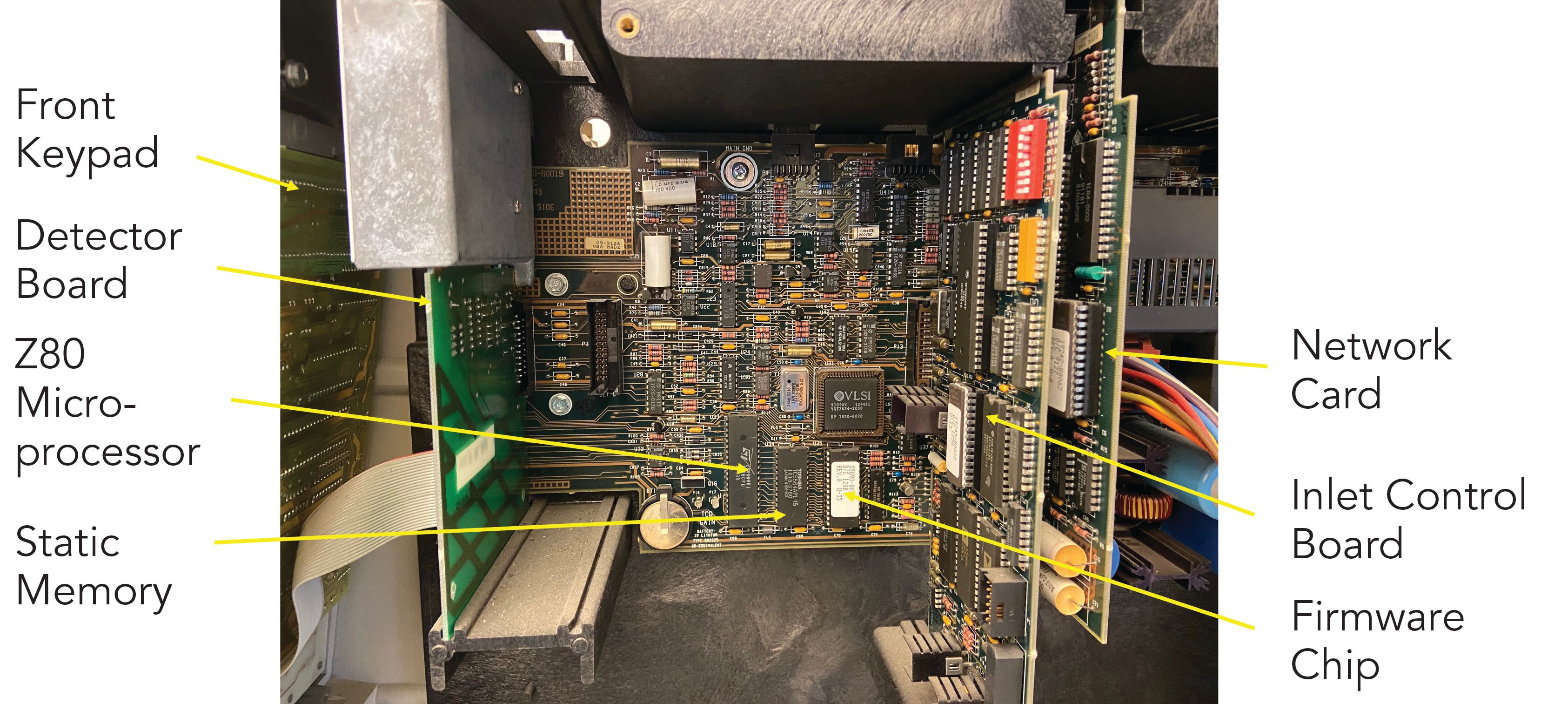
The chip with the white label is the instrument’s own firmware; the actual programming that runs the GC instrument. Between them is a static memory chip. Also note the accumulated dust from 30 years of service with never removing the panel covering the electronics. Like the interface boxes we discussed in September, the GC instrument is a computer in and of itself. The main board also includes connections for separate boards that control detectors (to the left in the picture), inlets (to the right) and network interfaces (to the far right). The keypad on the front panel of the instrument is connected by a ribbon cable to the far left of the motherboard, and the communications cables, which connect to the rear panel of the instrument, are on the far right.
Having seen how the various mechanical devices that are needed to operate a gas chromatograph work, we can now put these together with the possibilities for remote operation and data collection. External control of an instrument requires a system modern enough to allow a digital data system to control the functions of the instrument, either internally or externally, an interface to the Internet and control software that can operate over the Internet.
All of the devices we have discussed so far—potentiometers, relays, valve actuators, flow controllers, and regulators—have been miniaturized and placed on chips or in solid-state cartridges in most modern gas chromatographs. They can be easily actuated using the same low-voltage pulses (binary, on and off) involved with the transistor–transistor logic (TTL) and digital communications we discussed in September.
The development of solid-state electronic controls and devices for the various valves, switches, and controllers needed on a modern GC instrument have revolutionized instrument design and control. Miniaturized GC instruments designed from the “ground up” for capillary GC and ease of operation are now commonplace and have progressed greatly from the large, fully manual systems used in the 1970s. Connecting these microprocessor-controlled instruments directly to the Internet or through a company intranet provides the possibility of operating the instrument and analyzing the data remotely. Even as the instruments have become smaller and the once bulky control devices are now contained in solid-state electronic or pneumatic packs, the same basic electronic and mechanical controls still underlie instrument operation. By looking back at these more bulky components and how they operate, we can better understand what these automated devices are doing and how they are doing it.
References
(1) N.H. Snow, LCGC North Am. 38(9), 496–500 (2020).
(2) https://www.sciencehistory.org/ model-700-dual-column-gas-chromatograph
(3) N.H. Snow, LCGC North Am. 36(7), 448–454 (2018).

Nicholas H. Snow is the Founding Endowed Professor in the Department of Chemistry and Biochemistry at Seton Hall University, and an Adjunct Professor of Medical Science. During his 30 years as a chromatographer, he has published more than 70 refereed articles and book chapters and has given more than 200 presentations and short courses. He is interested in the fundamentals and applications of separation science, especially gas chromatography, sampling, and sample preparation for chemical analysis. His research group is very active, with ongoing projects using GC, GC–MS, two-dimensional GC, and extraction methods including headspace, liquid–liquid extraction, and solid-phase microextraction. Direct correspondence to: LCGCedit@mmhgroup.com

Fundamentals of Benchtop GC–MS Data Analysis and Terminology
April 5th 2025In this installment, we will review the fundamental terminology and data analysis principles in benchtop GC–MS. We will compare the three modes of analysis—full scan, extracted ion chromatograms, and selected ion monitoring—and see how each is used for quantitative and quantitative analysis.
Study Examines Impact of Zwitterionic Liquid Structures on Volatile Carboxylic Acid Separation in GC
March 28th 2025Iowa State University researchers evaluated imidazolium-based ZILs with sulfonate and triflimide anions to understand the influence of ZILs’ chemical structures on polar analyte separation.


