Valves for Chromatography (Part 2): Applications
Discussion about the use of gas switching valves for column backflush and two-dimensional series bypass applications.
In the second instalment of this series, John Hinshaw discusses the use of gas switching valves for column backflush and two-dimensional series-bypass applications.
Multidimensional gas chromatography (MDGC) as practiced today may be divided into two main application areas: Classical MDGC and comprehensive two-dimensional gas chromatography (GC×GC).
Classical MDGC involves redirecting a portion, or portions, of the eluent from one column to another column with different separation characteristics, at times that are synchronized with the elution of specific peaks (or groups of peaks) from the first column.
The more recent technique of GC×GC also involves the transfer of the eluent from one column to another, but the transfer occurs cyclically and continuously across the entire chromatogram without targeting the timing of individual peaks. All of the eluent from the first column is transferred to the second column so that all peaks are separated by both columns. The comprehensive approach yields resolving powers that approach the product of the first and second columns with a corresponding leap in data quantity and complexity. Increased knowledge and skills are required from the analyst to use this approach effectively in the routine laboratory.
This month's "GC Connections" will describe some basic examples of classical MDGC and offers insights into the more advanced methods of GC×GC.
Valve Applications
The injection of gaseous samples from a fixed-volume loop or the swapping of detectors during a GC analysis are two simple examples of ways that chromatographers use gas switching valves (GSVs).
The previous instalment (1) showed how these fundamental valve techniques work for packed and micropacked GC columns. Chromatographers also use valves in more complex ways, such as reversing the flow of carrier gas through a column, or to manipulate and redirect gas streams between two or more columns in multidimensional GC.
MDGC techniques enable the separation of a wide range of components that might not be achievable with a single column or in a single analysis. Separating a wide range of compounds with conventional single-column GC may require column temperature programming across a relatively large temperature range while MDGC could provide an equivalent separation isothermally, sometimes in combination with carrier gas pressure programming.
Dual-parallel-column analyses are possible, too, but sometimes it is not desirable to inject the entire sample onto both columns, especially if all injected substances cannot be cleared from both columns before a subsequent injection.
Performing a pair of discrete separations one after the other is also possible, but this method would also place the entire sample into each column, as well as taking the sum of both analysis times to be completed.
Before looking at multidimensional applications, we'll first take a look at a simple column flow-reversal application.
Backflushing
Chromatographers use column backflushing when the sample contains residual materials that would not otherwise be eluted from a column until well after all peaks of interest have been eluted; as an alternative to high-temperature column oven excursions where the upper temperature limit may be curtailed by the maximum temperatures allowed for the valves or column; or if temperature cycling is not otherwise required. Column and valve lifetimes can be extended by avoiding repeated high temperatures over long time periods. Backflushing works by removing late-eluting impurities from a column that might otherwise interfere with subsequent analyses.
Backflushing of a single column can be accomplished using the 6-port valve arrangement shown in Figure 1. In Figure 1(a) the 6-port valve starts in the backflush or standby position: carrier gas flow proceeds through the column from left to right as shown. The set-up is ready for injection after the sample fills the sample loop.
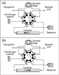
Figure 1
When the valve is moved to position (b) the sample loop is flushed by carrier gas flow onto the right-hand column connection as the column flow direction reverses and starts going from right to left. As long as the sample loop pressure is low, there is no danger of the sample flowing backwards into the carrier gas pneumatics because the carrier gas pressure is higher than the low-pressure end of the column at valve port 2 at the moment of injection.
The valve remains in the (b) position until the last peak of interest has been eluted. The valve is then returned to position (a), which causes the column flow to be restored to its original left-to-right direction (backwards in relation to the direction that the carrier gas flowed during peak elution). Any solutes or impurities left in the column at the backflush time will begin to move in reverse, towards the detector. As the total run time approaches twice the backflush time — assuming the carrier gas flow or pressure are not modified — residual material will be backflushed through the detector. At a time equal to approximately twice the backflush time nearly all of the material will have been flushed out. Some may remain as a result of band-broadening effects or nonlinear retention, so it is good practice not to perform another injection until sufficient additional time has passed in the backflush mode to remove all residual material.
Figure 2(a) illustrates a backflushed chromatogram of a simple gas mixture. In Figure 2(b), the backflushed portion of the chromatogram is enlarged 200× to show a momentary baseline disturbance at the backflush time of 480 s, followed by some unidentified C3 and heavier compounds and a return to baseline before 960 s, at twice the backflushing time. Although the impurity levels are relatively low in this example, if they are not purged from the column after each run such extraneous non-eluted material could build up over many runs and cause baseline instability. Other examples include natural gas analysis with grouping of C6+ compounds, environmental extracts with high-boiling matrix compounds and food and beverage volatiles.
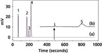
Figure 2
The example shown here was performed on a micropacked column. The principles of backflushing for open-tubular columns are similar, but because of the low dead-volume requirements such separations may be better managed with various fluidic capillary switching devices. A future instalment of "GC Connections" will address these configurations and their applications.
Column Sequence Reversal
Some columns yield good separations for certain compounds but not for others. For example, a molecular sieves column discriminates between various light gases such as hydrogen, oxygen, nitrogen and carbon monoxide, but fails to separate water or carbon dioxide.
These two compounds will contaminate a molecular sieves column until baked off at high temperatures, and if they are allowed to accumulate they will degrade the separation of other compounds on the molecular sieves column. On the other hand, certain porous polymer columns easily separate water and carbon dioxide as well as a variety of hydrocarbons and other gases, but may not produce acceptable separations of those gases handled well by molecular sieves.
It is possible to combine the separation capabilities of these two columns for a complete separation of fixed gases and C1 to C3 hydrocarbons. The rest of this instalment will address the separation of these solutes in a couple of different ways. Other examples for different sets of solutes are easy to find in the chromatography literature.
Two popular methods for this type of combined column two-dimensional separation are sequence-reversal and series-bypass operation. In both cases, the flow and connections between two columns are manipulated during the analysis via valve operations so that each column receives and separates the peaks that it is best suited for.
The main differences between sequence reversal and series-bypass operations is that the former uses a single detector or two detectors in series, while the latter can use two discrete detectors for true dual simultaneous separations. Column sequence reversal is illustrated by the flow diagram in Figure 3; this configuration uses a 10-port valve. The details are not shown here for reasons of space, but several examples can be found on the manufacturers' websites.
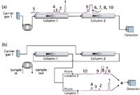
Figure 3
In sequence reversal some care must be taken to ensure that peaks from one column are not co-eluted with peaks from the other. Figure 3(a) illustrates the column flows in the first step of injection with sequential flow from column 1 to column 2.
The sample is injected from the sample loop into column 1. The initial, partially-separated peaks from column 1 enter column 2 until those peaks destined to be separated on column 2 have been transferred. The valve is then moved to change to flow as shown in Figure 3(b); the sequence of the columns is reversed.
Peaks remaining in column 1 continue to partition and move along the column until they are subsequently eluted and detected. Simultaneously, peaks from column 2 are eluted into column 1, pass through it with little to no additional retention, and enter the detector. Co-elution of peaks in a complex mixture such as in this example may be difficult to avoid. In some applications it may be necessary to add a second valve to stop flow in column 2 and delay its peaks from entering column 1 until the existing peaks in column 1 have been eluted.
A related configuration keeps the second column flowing to the detector, but backflushes the first column to vent after the solutes to be separated on the second column have left the first column. An independent carrier gas source may be used for backflushing the first column. This configuration is sometimes called pre-column backflushing, and can also be found in manufacturers' literature. It is useful when only the peaks from the second column are to be analysed, and the remaining peaks in the first column can be discarded.
Series-Bypass Backflush Operation
For the application at hand, what we really want to accomplish is the simultaneous determination of all of the peaks. This can be made possible by combining the two applications discussed so far, backflushing and column-to-column flow redirection. The backflush application shown in Figure 1 is augmented by replacing the 6-port valve with a 10-port valve, and an additional 6-port valve, carrier gas source and detector are added. The 10-port valve provides the backflush functionality, and the 6-port valve controls the destination of the effluent from column 1 — either to column 2 or to detector 1 through a restrictor — while generating functionality similar to that of the sequence-reversal configuration of Figure 3.
Figure 4 illustrates the flow paths of a series-bypass backflush configuration. In Figure 4(a) residual material from a previous injection is backflushed from column 1 to detector 1. The configuration remains in this position until the sample loop is filled and injection may be started. Figure 4(b) shows the flows for injection and series operation of column 1 into column 2. Here, the contents of the sample loop are injected into column 1 and the initial unresolved fixed-gas peaks plus methane are passed in series onto column 2. After the methane peak passes into column 2, the valves are repositioned to produce the flow paths shown in Figure 4(c).
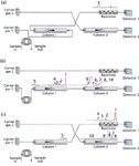
Figure 4
Column 1 now bypasses column 2, and both columns flow to their respective detectors. The solutes that were initially passed from column 1 to column 2 are eluted into detector 2, while the remaining target peaks from column 1 are eluted into detector 1. After the column 1 target peaks have been eluted, the flows are reset to position (a), so that any remaining contaminants in column 1 are backflushed to detector 1. The restrictor, which has similar flow characteristics to column 2, serves to maintain a more constant flow in column 1 as it is switched in front of column 2 and back again.
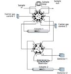
Figure 5
The valve plumbing for the series-bypass backflush configuration is shown in Figure 5. The 10-port valve provides sample injection and backflush functionality, while the 6-port valve selects whether column 1 effluent is directed to column 2 or to detector 1 via the restrictor. The valve positions in Figure 5 that correlate with the three flow configurations of Figure 4 are listed in Table 1.

Table 1: Valve positions for Figure 5 to achieve flow paths diagrammed in Figure 4.
The timing of the bypass operation is important. If the first column is bypassed around the second column too soon, then some of the peaks that should enter the second column do not. If the bypass time is set too long, then some of the peaks that should remain in the first column can enter the second column instead. Figure 6 shows the effects of increasing the bypass time by 20s. The methane peak is split between the first and second columns with a 60-s bypass time. Increasing the bypass time by 20 s results in all of the methane appearing on the second column. This timing must be revalidated any time the flow, temperatures or the columns themselves are changed. The timing of the backflush operation, at 480 s in this example, is not as critical and can occur at any time that the transient spike does not interfere with a peak, once all of the peaks of interest have been eluted from column 1.
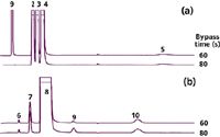
Figure 6
Conclusion
This month's instalment examined the basics of valve applications for backflushing, sequence reversal and pre-column bypassing. We then combined these basic techniques to create a hybrid dual-valve configuration capable of separating both fixed gases and hydrocarbons in a single two-dimensional analysis. MDGC presents a powerful suite of techniques that analytical chemists can use to tease apart solutes that might otherwise be inseparable, at least without significant additional effort. The next instalment in this series will discuss multidimensional separations as applied to open-tubular columns; including fluidic flow switching and applications to heart-cutting, selectivity tuning of serially connected columns and GC×GC separations.
"GC Connections" editor John V. Hinshaw is senior research scientist at BPL Global Ltd, Hillsboro, Oregon, USA and a member of LCGC Europe's editorial advisory board. Direct correspondence about this column should go to LCGC Europe editor, Alasdair Matheson, 4A Bridgegate Pavilion, Chester Business Park, Wrexham Road, Chester, CH4 9QH UK, or e-mail: amatheson@advanstar.com
References
1. J. Hinshaw, LCGC Eur., 24(3), 150–154 (2011).

Study Examines Impact of Zwitterionic Liquid Structures on Volatile Carboxylic Acid Separation in GC
March 28th 2025Iowa State University researchers evaluated imidazolium-based ZILs with sulfonate and triflimide anions to understand the influence of ZILs’ chemical structures on polar analyte separation.
Quantifying Microplastics in Meconium Samples Using Pyrolysis–GC-MS
March 26th 2025Using pyrolysis-gas chromatography and mass spectrometry, scientists from Fudan University and the Putuo District Center for Disease Control and Prevention detected and quantified microplastics in newborn stool samples.


