Selectivity in Reversed-Phase Separations (Part 3): Column-type Selectivity
How to choose another column to try and solve a separation problem.
In the first two instalments of this series, we've looked at different factors that influence selectivity in reversed-phase liquid chromatography (LC) separations. First, we saw some of the benefits of changing solvent type,1 such as a change from methanol to acetonitrile or tetrahydrofuran. Next, we looked at how a change in the solvent strength2 — the percentage of organic solvent in the mobile phase — was an easier adjustment to make and often had suitable "leverage" to pull apart problem peak pairs. This month's "LC Troubleshooting" will focus on another common technique used to change peak spacing in a chromatogram: changing from one column type to another.
Not All C18s Are Equal
When I first started using LC, it was thought widely that all C18 columns would give equivalent separations. In fact, the United States Pharmacopoeia (USP) in its column classification scheme classifies C18 columns as "L1 — octadecyl silane chemically bonded to porous silica or ceramic micro-particles, 1.5 to 10 µm in diameter, or a monolithic silica rod".3 Over the past 40 years, however, we've all come to recognize that all C18s are not created equal — many will give dramatically different separations. In the current listing, the L-classification scheme contains 74 different column types,3 including C18, C8, phenyl, cyano and many others. Even columns that have the same label, such as C18 or phenyl, may have significantly different selectivity characteristics. It is not clear how many different reversedphase columns are available, but by some estimates there are at least 1000.4 In our work at LC Resources, we've tested more than 500 different reversed-phase columns.

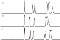
Figure 1: Comparison of simulated chromatograms for C18 columns from three manufacturers. Column dimensions: 150 mm à 4.6 mm, 5 μm particles; mobile phase: 50:50 acetonitrileâ30 mM phosphate buffer (pH 2.8); temperature: 35 °C; column efficiency N: 10000. Retention normalized to peak 1. See Table 1 for column information and text for details. Peaks: 1 = anisole, 2 = n-butylbenzoic acid, 3 = toluene, 4 = mefenamic acid, 5 = ethylbenzene, 6 = trans-chalcone.
So how different are C18 columns from each other? To illustrate this, I've chosen a set of six test compounds that should be fairly well-behaved (see caption of Figure 1 for their identities). That is, at low pH (pH 2.8), they are neutral or un-ionized, so ionic interactions with the column should be minimal. I arbitrarily chose three C18 columns from our database.5 These are from well-known sources and are all type-B, high-purity silica columns. These are simulated separations on 150 mm × 4.6 mm columns packed with 5 µm particles and generating 10000 plates. For simplified comparisons, I've normalized retention to the first peak (anisole). The first column [Figure 1(a)] is our reference column. You can see that peaks 4 and 6 overlap and the resolution is marginal for peaks 2 and 3. If we change to another manufacturer's C18 column [Figure 1(b)], the separation of peaks 2 and 3 is improved, and the separation of the last three peaks has changed, but it is no better than the reference column. A third manufacturer's C18 [Figure 1(c)] is no better — it shows a good separation for peaks 2 and 3, but peaks 4 and 6 still overlap. You can see in Figure 1 that, although the first three peaks are separated by all three columns, the selectivity (relative peak spacing) is different for these peaks. And none of the three columns can separate the last three peaks — even the peak order changes! So you can't arbitrarily swap one C18 for another and expect the same results. But on the other hand, the differences aren't enough that we can make the same change and expect to solve a separation problem. Although there is likely at least one manufacturer's C18 column that will separate all six compounds, changing from one to another in an effort to get the desired separation is not a very good strategy.
Alternate Stationary Phases
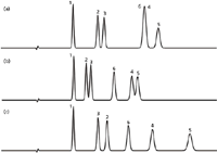
Another technique that has been around as long as I have been doing chromatography is to change the stationary phase. That is, users change from a C18 to a phenyl or cyano or embedded polar phase. We can use the same sample and conditions to see what happens in this case. I've chosen columns from the same manufacturer as the reference column of Figure 1(a). This separation is repeated in Figure 2(a) (with a slightly extended time axis). The sample was then run on the same brand of column from the same manufacturer, but with a phenyl stationary phase for the separation of Figure 2(b). The separation of the phenyl column might be expected to be much different from the C18, because there is aromatic nature to the sample components. The phenyl column separates all the peaks, but not to baseline. We could probably adjust the mobile phase or reduce the particle size (or both) to get baseline separation with this column. Figure 2(c) shows the separation on the same manufacturer's embeddedpolar-group (EPG) phase. This column provides a good separation of all the peaks, certainly the best so far. Notice also that peaks 2 and 3 are reversed with the EPG column. The differences between the columns are assumed to be only the stationary phase — the silica particle chemistry should be the same. This technique, of changing to a different stationary phase from the same manufacturer, is one that many people have had success with over the years, but it still involves trial and error, without a certainty of a satisfactory separation.

Figure 2: Comparison of chromatograms for (a) C18, (b) phenyl and (c) embedded-polar-group columns from same manufacturer. Other conditions as in Figure 1; see text for details.
Database Help
Still another way to pick a column that is likely to have different selectivity is to use the column database on the USP website.5 As explained in earlier articles in LCGC6,7 and elsewhere (for example, see reference 8), this database with more than 500 reversed-phase columns can be used to pick similar (equivalent) or different (orthogonal) columns compared to some reference column, such as the one you have already tried. By choosing the "view different columns" option, you can see what columns are most different from the reference column. I tried this out for the present sample containing some acids and neutral compounds at low mobile-phase pH. As my reference column, I chose the same C18 column we used in Figures 1(a) and 2(a), and have repeated the separation as Figure 3(a) (different time axis than the other figures). One of the most orthogonal columns with type-B silica particles (use of the older, low purity, type-A particles is discouraged for new separations) is the one used to obtain the separation shown in Figure 3(b). This is an EPG column from a different manufacturer than the reference column of Figure 3(a). So we've taken advantage of both a change in the stationary phase and a change in the silica source for added selectivity potential. The change is dramatic. Peak 5 has moved forward between 1 and 2, and peak 6 has moved up between 2 and 3. This is definitely a change in selectivity. There is no guarantee that the recommended column will separate all the compounds in your sample, but there is a high probability that the separation will look much different, especially if you take advantage of other selectivity variables. In one collaborative study,9 several pharmaceutical laboratories tested this approach on typical samples that they encounter, and in all 11 of the cases checked, the predicted orthogonal column indeed gave a significantly different separation.

Figure 3: Comparison of separations obtained using (a) a C18 column from one manufacturer with (b) an embedded-polar-group column from a second manufacturer. Other conditions as in Figure 1; see text for details.
Comparing Column Selectivity
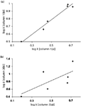
We can make visual comparisons and see that, for the present sample, a change from the column of Figure 1(a) [same as Figures 2(a) and 3(a)] to the column of Figure 2(c) or 3(b) would allow us to separate all the peaks. But which of these separations gives us the largest change? When comparing the selectivity changes when a change in column is made, it is nice to have a quantitative measure of the change. One way to do this is to make a graphic comparison of selectivity. This can be achieved by plotting the retention on one column vs the retention on a second column. An example of this for the columns of Figure 1(a) and 1(b) is shown in Figure 4(a). (Note that plots like this are most useful if we plot the log of the retention factor, k, for each column.) The scatter about the trend line in the plot is a measure of how different the selectivity is between the two columns. The data cluster tightly about the trend line, and r2 = 0.97 (Table 1) confirms this. Contrast this result to that of Figure 4(b), where the columns of Figure 3(a) and 3(b) are compared. Here, there is much more scatter (r2 = 0.49), showing that the selectivity is very different between the two columns.

Figure 4: Plots of log k vs log k for sample of Figure 1. (a) Column of Figure 1(a) vs 1(b); (b) column of Figure 3(a) vs 3(b). Other conditions as in Figure 1; see text for details.
An actual calculation of the change in selectivity, α, is an even better way to compare two columns. Recall that
α = k2/ k1 [1]
where k1 and k2 are the retention factors for two peaks. The change in log α between the two columns is related to how far the data points are from the trendline in plots of log k vs log k, as in Figure 4. The larger the average change in log ͍, |δlog α|avg, between two columns, the more different the chromatogram will appear. This measure of change in selectivity, |δlog α|avg, is directly related to the standard error (SE) of the plot as
|δlog α|avg = 1.4 SE [2]
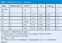
so it is easy to calculate from plots such as Figure 4. Other work has shown that when selectivity is changed in a reversed-phase separation, whether by a change in column or some other variable (for example, solvent type or solvent strength), a value of |δlog α|avg ≥ 0.1 gives a high probability that the separation will be orthogonal (or significantly different).9 For the present examples, I have made these calculations for the various columns when compared to the reference column [Figures 1(a), 2(a), 3(a)] and summarized them in Table 1. You can see that the column of Figure 2(c) almost reaches the desired change, but that the column of Figure 3(b) has a value of |δlog α|avg that is more than twice as large as the minimum recommendation. This confirms once more our visual observation of the separation that is most different from the original.

Table 1: Comparison of column selectivity.
The USP column database5 gives still another measure of differences in column selectivity. This is the Fs-value calculated from the column characteristics in the database.8 In one study with 67 different compounds of widely varying structure, including acids, bases and neutrals, it was determined that Fs > 65 ≈ |δlog α|avg ≥ 0.19.9 This means that the database can be used to look for columns with large Fs-values compared to the current (reference) column, thus giving you confidence that peak-spacing changes will be significant. I have tabulated the Fs-values in Table 1 for the six columns we have been examining and the selected sample (neutrals and un-ionized acids). You can see that the column of Figure 3(b) has Fs = 55, whereas all of the other columns have Fs ≤ 16, once more confirming the visual observations that this is the most orthogonal column of the set.
Conclusions
We have seen that a change in column chemistry can be a powerful tool to change selectivity in a reversed-phase separation. A change from one manufacturer's C18 to one from another manufacturer generally gives marginal gains, as was seen in Figure 1. A more effective way to make the change is to try a different stationary phase. If this change is made within one product line of columns, where the same silica support material is assumed, the change will result from a change in the bonded phase alone. This was shown in Figure 2 for three different bonded phases from the same product line from a single manufacturer. To gain even more leverage in the separation, a change in the base silica along with a change in bonded phase can be made. Although this may be possible within one manufacturer's products, such as by changing to a different bonded phase from a different product line of columns, such a change is more likely if the change is made in both the manufacturer and bonded phase, as shown in Figure 3.
Using a change in the column to change peak spacing comes with risks of making a poor choice [as in Figure 1 or Figure 2(b)]. Such results also can be costly, because columns are expensive and research time is valuable. A more productive technique is to use some foreknowledge of selectivity differences between specific columns, such as that available in the USP database.5 By using the database, it is easy to identify columns that are most likely to have different selectivity.
When exploring changes in selectivity, it probably will be more practical to explore solvent-type selectivity1 or solvent-strength selectivity2 before column-type selectivity, just because it is less expensive. However, armed with the information we've covered in this discussion, you can make intelligent choices about a change in column, so you can increase the return on the investment in a new column in an effort to change selectivity. When this is taken into account, you may find that screening several columns of different selectivity is a fruitful investment of time early in the separation development process.
"LC Troubleshooting" editor John Dolan is vice president of LC Resources, Walnut Creek, California, USA. He is also a member of LCGC Europe's editorial advisory board. Direct correspondence about this column should go to to LCGC Europe editor, Alasdair Matheson, at Advanstar Communications, Bridgegate Pavillion, Chester Business Park, Wrexham Road, Chester CH4 9QH, UK, or e-mail amatheson@advanstar.com
References
1. J.W. Dolan, LCGC North America, 28(12), 1022–1027 (2010).
2. J.W. Dolan, LCGC North America, 29(1), 28–34 (2011).
3. United States Pharmacopeia, USP 34 NF 29, 982–983 (2011).
4. R.E. Majors, personal communication.
5. PQRI database at http://www.usp.org/USPNF/columns.html
6. J.W. Dolan, LCGC North America, 25(10), 1014–1020 (2007).
7. L.R. Snyder et al., LCGC North America, 28(6), 418–430 (2010).
8. L.R. Snyder, J.W. Dolan and P.W. Carr, Anal. Chem., 79, 3254–3262 (2007).
9. J. Pellett et al., J. Chromatogr. A, 1101,122–135 (2006).

Removing Double-Stranded RNA Impurities Using Chromatography
April 8th 2025Researchers from Agency for Science, Technology and Research in Singapore recently published a review article exploring how chromatography can be used to remove double-stranded RNA impurities during mRNA therapeutics production.
Study Explores Thin-Film Extraction of Biogenic Amines via HPLC-MS/MS
March 27th 2025Scientists from Tabriz University and the University of Tabriz explored cellulose acetate-UiO-66-COOH as an affordable coating sorbent for thin film extraction of biogenic amines from cheese and alcohol-free beverages using HPLC-MS/MS.


