Essentials of LC Troubleshooting, Part IV: What Is Going On with the Baseline?
Some liquid chromatography (LC) troubleshooting topics never get old because there are some problems that persist in the practice of LC, even as instrument technology improves over time. There are many ways for things to go wrong in an LC system that ultimately manifest as detector baselines that do not look right. Developing a short list of the likely causes of these results can help streamline our troubleshooting experience when baseline-related problems occur.
Writing this “LC Troubleshooting” column and thinking about topics each month is interesting in the sense that there are some topics that just never get old. Whereas in the chromatography research world certain topics or ideas become obsolete as they are displaced by newer and better ideas, there are certain topics in the troubleshooting world that have remained relevant since the very first troubleshooting article appeared in this magazine in 1983 (1). Over the last few years, I focused several “LC Troubleshooting” installments on contemporary trends (for example, the relatively recent advances in our understanding of the effects of pressure on retention [2]) in liquid chromatography (LC) that are affecting the way we approach our interpretation of LC results, and how we approach troubleshooting with modern LC instruments. In this installment, I am continuing a series that I started back in December 2021 (3) that focuses on some of the “bread and butter” topics of LC troubleshooting—those elements that are essential for any troubleshooter, no matter the vintage of the system we are working with. The topics at the heart of this series are highly related to LCGC’s well-known “LC Troubleshooting” wall chart (4) that hangs in many laboratories. The fourth installment in this series focuses on problems related to detector baselines that do not look right. As with all of the “essential” troubleshooting topics, problems with baselines have been discussed in “LC Troubleshooting” articles in the past (5). However, the solutions to these problems have changed over time. The causes of these anomalous baselines can have chemical or physical origins, or both. Discussing some of the most commonly observed causes empowers users to spot these problems when they occur, and it enables them get a start on the troubleshooting effort by narrowing the list of possibilities to investigate and the range of possible solutions. I hope LC users young and old will find the tips and reminders related to this important topic in this column useful.
Everything is Possible
More often than not, I find myself responding to troubleshooting questions with “Everything is possible,” which might seem like an easy out when considering observations that are hard to explain, but I find that this response is appropriate more often than not. With so many possible causes of bad detector baselines, it is important to keep an open mind when considering what might be the problem. Even aspects of LC systems and methods that are normally well controlled (for example, mobile phase solvent quality) can change suddenly. Therefore, it is important to consider a wide range of potential causes of a bad baseline, even if most of them are normally not a concern.
What Is to Be Expected?
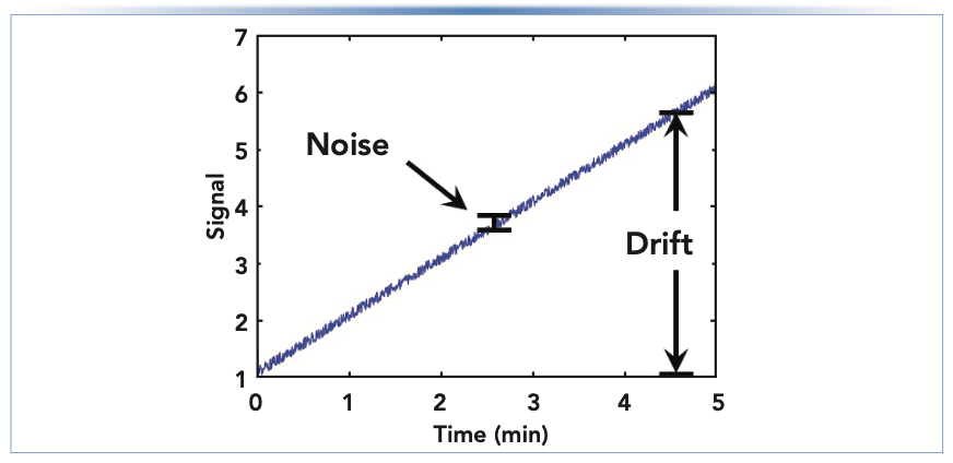
A critical step in any troubleshooting exercise—but one that I think is not appreciated enough—is recognizing that there is a problem to be solved. Recognizing that there is a problem usually amounts to recognizing that what is happening with the instrument is different from what is expected to happen. Our expectations are formed from theories, empirical knowledge, and experience (6). “Normal” baselines can look very different, depending on the chromatographic conditions and detector type in use. An ideal detector baseline is flat (that is, no drift), with a low degree of noise in the signal and free of artifacts such as “ghost peaks” or other features in the signal that are not related to the analytes we are trying to separate. Figure 1 illustrates the difference between detector “drift” and “noise” in the signal. The closer our real detector baselines are to this ideal, the more powerful our methods are for quantifying analytes accurately, with confidence, and at low concentrations.
FIGURE 1: Illustration of detector “drift” and “noise” in the signal.
Chemical Causes of Baseline Anomalies
In my laboratory, we observed several different types of baseline anomalies that we ultimately attributed to problems with the reagents used to prepare mobile phases.
Cause #1: Mobile Phase Impurities That Accumulate On-Column
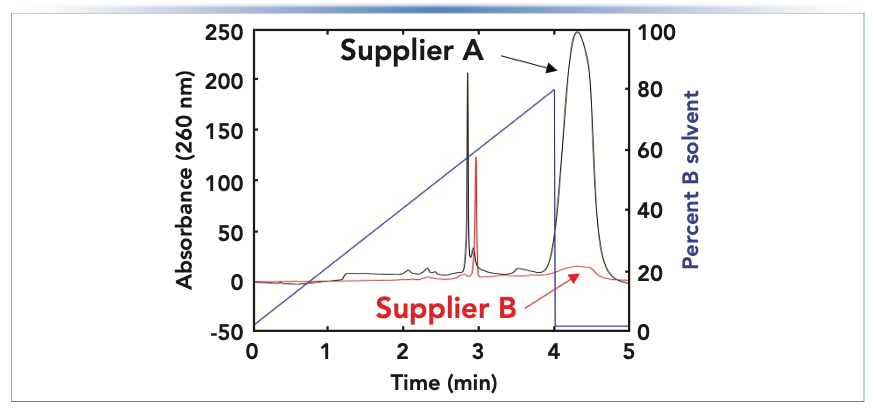
Occasionally, mobile phase solvents (for example, water and acetonitrile) or additives (for example, formic acid and triethylamine) contain impurities that are highly retained under the conditions of a chromatographic experiment. When using isocratic methods, accumulation may not become apparent until the column is “washed” with a strong solvent (for example, a high level of acetonitrile) at the end of a series of sample injections or prior to storing the column. During the washing step, elution of the impurities that had accumulated on the column will be observed as a large, broad change in the detector signal. When using gradient elution methods, impurities are retained by the column early in the gradient, but then they are washed out in the middle of the gradient or during a washing step at the end of the gradient. Figure 2 shows an example of this occurrence from our recent work aimed at developing a reversed-phase (RP) method that involves dimethylcyclohexylamine in the A solvent used in the gradient. With the mobile phase from supplier A, a large impurity peak is observed at the end of the gradient, whereas this peak is much smaller when using the mobile phase prepared with the additive obtained from supplier B.
FIGURE 2: Comparison of detector baselines observed for a reversed-phase LC (RPLC) separation when using mobile phases prepared using dimethylcyclohexylamine as a mobile phase additive (in the A solvent), obtained from two different suppliers (A and B). The large impurity peak appears after the solvent composition reaches 80% B at the end of the gradient.
Cause #2: Mobile Phase Impurities That Contribute to High and Changing Baselines
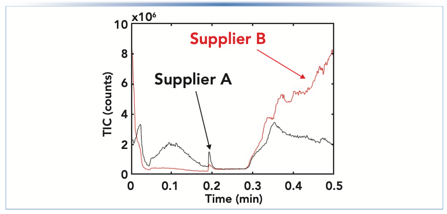
In specific cases where the impurities are highly soluble in the mobile phase, they are not retained by the column and contribute toward a higher-than-normal detector signal throughout the chromatogram. When using gradient elution, if the impurities are only present in one of the solvents used in the gradient (for example, only in the mainly aqueous solvent used in a gradient for a reversed-phase separation), then the detector signal may change slowly and in relation to the fraction of that solvent contributing to the mobile phase at any point in time. Figure 3 shows an example of this occurring from our recent work involving mass spectrometric detection. In this case, we ultimately found that the higher-than-expected signal was because of the presence of short chain alkylamines present in the isopropanol we were using as a component of our mobile phase. This particular case was quite surprising given that the isopropanol we had sourced was sold as a “liquid chromatography–mass spectrometry (LC–MS) grade” solvent. Changing to isopropanol from a different manufacturer immediately solved the problem, which is shown in the chromatograms in Figure 3.
FIGURE 3: Comparison of mass spectrometric total ion current (TIC) during a solvent gradient (0–0.5 min) running from a low to high concentration of isopropanol in the mobile phase (supplier A vs. supplier B).
Cause #3: Mobile Phase Impurities That Produce “Ghost Peaks”
In cases similar to those discussed in the preceding two sections, the mobile phase impurities do not manifest as signal features that look like typical chromatographic peaks. Therefore, they don’t directly conflict with analyte peaks per se. However, if the physicochemical properties of the impurities are similar to the analytes of interest in a separation, then the impurities can manifest as features in the baseline that look like typical peaks. These are sometimes referred to as “ghost peaks,” because they persist in the baseline even when no sample is injected. This topic has been discussed many times in the history of the “LC Troubleshooting” column (11 articles use the keyword “ghost peak!”), and, on several occasions, an entire installment has been committed to the topic. Readers interested in this particular type of baseline are referred to these articles, the most recent of which was published in October 2016 (7).
Physical and Physicochemical Causes of Baseline Anomalies
In addition to the chemical causes of baseline problems discussed in the previous section, there are many other causes that are either purely physical in nature or can be characterized as having both chemical and physical components (that is, physicochemical).
Cause #1: Detector Response to a Major Mobile Phase Component
Sometimes, small changes in the preparation of solvents used for a LC method can have a dramatic effect on the appearance of the baseline. A classic example of this effect is the change from a phosphate-buffered mobile phase to one involving formic acid as an additive. Whereas phosphate species are highly transparent to UV light down to approximately 200 nm, carboxylate species (such as formate, acetate) absorb much more than phosphates below approximately 230 nm.
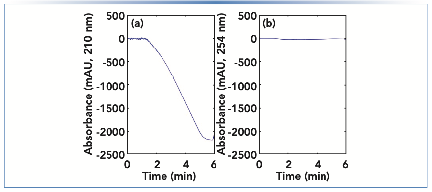
This difference is readily observed when gradient elution is used, and the additive is only present in one of the solvents used in the mobile phase gradient (for example, the majority aqueous solvent). Figure 4 shows the detector baselines observed in such a case, where we see that the absorbance at 210 nm decreases dramatically, and roughly in proportion to the composition of the A/B solvent mixture in the mobile phase at any point during the gradient. On the other hand, the absorbance at 254 nm is relatively unchanged during the gradient because the formate additive absorbs very little at this wavelength. The most frequently used solutions to the dramatically changing baseline are to either use a higher wavelength where the additive does not absorb so much light (as in [B]), or to add a similar concentration of the additive to the B solvent used in the gradient so that a change in the A/B solvent mixture does not significantly change the concentration of the additive arriving at the detector.
FIGURE 4: Comparison of detector baselines when using ammonium formate as a mobile phase additive in only the majority aqueous solvent, and UV absorbance detection at either (a) 210 nm or (b) 254 nm.
Cause #2: Inconsistent Mobile Phase Composition Because of Pump Problems
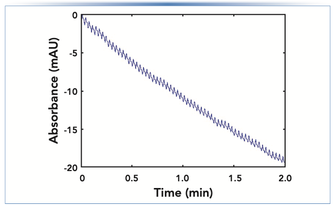
Recently, I’ve written about ways that things can go wrong with modern high performance LC (HPLC) pumps (3). Sticky check valves and trapped air bubbles are common causes of inconsistent flow from a high pressure pump head. When one of the two pumps in a binary pumping system fails, it can lead to extreme changes in the mobile phase composition that go through the HPLC column and eventually to the detector. If the detector in use is sensitive to these changes in composition, then an anomalous detector baseline can be a symptom of a problem that is really caused by the pump. An extreme example is a situation where the A solvent contains ammonium acetate, the B solvent is acetonitrile, and UV detection is used at 210 nm. In this case, the A solvent absorbs much more light than the B solvent, but if the composition of the A/B mixture is consistent over time, a smooth, flat detector baseline will be observed. However, if the flow from the A channel becomes inconsistent because of a check valve problem or an air bubble, then the composition of the A/B mixture will not be consistent, leading to a saw-tooth pattern in the baseline. An example of such a scenario is shown in Figure 5. This pattern in the signal is distinctly different from patterns that emerge because of other problems discussed in this installment and can be readily recognized. Readers interested in troubleshooting pump problems that could be the ultimate cause of this type of observation are referred to previous “LC Troubleshooting” articles on this topic (for example, [3]).
FIGURE 5: Bad detector baseline because of an inconsistent flow from one channel of a binary pumping system.
Cause #3: Temperature Effects
Different detectors are affected by changes in temperature in different ways. The signal baseline for refractive index (RI) detection is notoriously sensitive to changes in temperature. Therefore, stabilizing the temperature of the detector itself and the laboratory environment will help minimize drift in the baseline. UV absorbance detectors are also prone to changes in temperature, which causes drift in the baseline, but to a lesser extent when compared to RI detectors. Modern UV detector designs are much less susceptible to changes in laboratory temperature than the older designs were in the past.
Cause #4: Baselines That Are Too “Fuzzy”
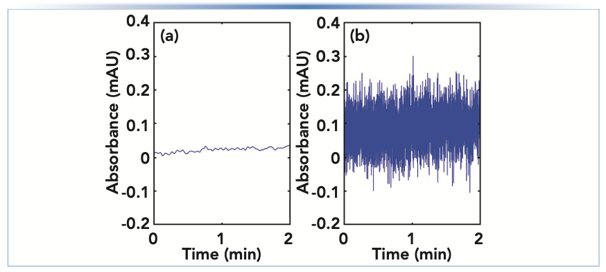
Figure 1 illustrates the difference between “drift” in detector baseline (the slow changing, or low frequency features), and “noise” in the signal (the fast changing, or high frequency features). Many of the problems discussed so far in this installment cause slow changes in the detector signal, but there are also many potential causes of noise that is larger than expected, which we sometimes refer to as “fuzzy” baselines. First, a data acquisition rate that is higher than normal will lead to baselines that look fuzzier than normal because the actual short-term variations in the signal are revealed when a high acquisition rate is used, that would otherwise be hidden when using a lower acquisition rate. Figure 6 shows a comparison of baselines (UV detection) obtained with otherwise identical conditions, but one at a relatively high acquisition rate of 160 points/s (B), and one at a much lower rate of 2.5 points/s (A). If a method is inadvertently or unintentionally set to a high acquisition rate, then simply reverting to a lower rate will yield a much smoother baseline. However, do be careful not to use an acquisition rate that is so low that it causes artificial broadening of the chromatographic peaks of interest (8).
FIGURE 6: Comparison of UV absorbance detector baselines obtained with data acquisition rates of (a) 2.5 or (b) 160 points per second.
Second, when using spectroscopic detectors, conditions that lead to a small amount of light reaching the detector can also lead to fuzzy baselines. In the case of UV absorbance detection, this phenomenon can occur when a) the lamp is not producing the correct amount of light (for example, if the lamp has exceeded its lifetime or has not been turned on); b) something in the mobile phase is absorbing a large fraction of the light at the wavelength being monitored (for example, detecting below 220 nm when using a high concentration of formic acid); or c) partial or total occlusion of the light path between the lamp and the detector because of improper installation of a flow cell or some other blockage. Most modern HPLC systems are supported with software that includes many diagnostic tests, one of which will test for “lamp intensity” for a UV detector. If weak lamp output or partial occlusion of the light path is suspected as a cause of a fuzzy baseline, running this diagnostic test is a good place to start the troubleshooting process.
Summary
In this fourth installment on essential topics in LC troubleshooting, I discussed some of the causes of anomalous baselines. Most problems fall into one of two categories—problems characterized by baseline drift (low frequency signal changes) or excessive noise (high frequency signal changes). These problems can have chemical or physical origins. Similar to other essential troubleshooting topics, effectively troubleshooting baseline problems starts with a clear expectation of what a typical baseline looks like for the application at hand, and then narrowing down the list of possible causes by the type of anomaly (drift vs. noise). Understanding these details provides a good place to start troubleshooting, but does not capture all possibilities. Readers interested in learning about a deeper list of causes and solutions for problems related to detector baselines are referred to the LCGC Troubleshooting Guide wall chart.
Acknowledgments
I’d like to thank Tina Dahlseid, Maria Sylvester, Henry Noma, and Zach Kruger for supplying some of the data shown in this article.
References
(1) D. Runser, An HPLC troubleshooting guide, LC Magazine. 1, 10–16 (1983).
(2) T. Kempen and D.R. Stoll, LCGC North Am. 39, 471–475 (2021).
(3) D.R. Stoll, LCGC North Am. 39, 572–574 (2021).
(4) LCGC North America, LCGC Troubleshooting Wallchart. https://www.chromatographyonline.com/view/troubleshooting-wallchart (accessed July 2022).
(5) K. Christianson and J. Dolan, LCGC 15, 928–934 (1997).
(6) D.R. Stoll, LCGC North Am. 38, 505–509 (2020).
(7) J.W. Dolan, LCGC North Am. 34, 778–785 (2016).
(8) M.F. Wahab, P.K. Dasgupta, A.F. Kadjo, and D.W. Armstrong, Anal. Chim. Acta. 907, 31–44 (2016). https://doi.org/10.1016/j.aca.2015.11.043.
ABOUT THE COLUMN EDITOR
Dwight R. Stoll is the editor of “LC Troubleshooting.” Stoll is a professor and the co-chair of chemistry at Gustavus Adolphus College in St. Peter, Minnesota. His primary research focus is on the development of 2D-LC for both targeted and untargeted analyses. He has authored or coauthored more than 75 peer-reviewed publications and four book chapters in separation science and more than 100 conference presentations. He is also a member of LCGC’s editorial advisory board. Direct correspondence to: LCGCedit@mmhgroup.com


Polysorbate Quantification and Degradation Analysis via LC and Charged Aerosol Detection
April 9th 2025Scientists from ThermoFisher Scientific published a review article in the Journal of Chromatography A that provided an overview of HPLC analysis using charged aerosol detection can help with polysorbate quantification.
Removing Double-Stranded RNA Impurities Using Chromatography
April 8th 2025Researchers from Agency for Science, Technology and Research in Singapore recently published a review article exploring how chromatography can be used to remove double-stranded RNA impurities during mRNA therapeutics production.


