Modern HPLC Pumps: Perspectives, Principles, and Practices
LCGC North America
Gaining a solid understanding of how HPLC instrumentation works will help you achieve success in the analytical laboratory. This four-part series is here to guide you, starting with pumps.
This installment is the first of a series of four white papers on high performance liquid chromatography (HPLC) modules (pump, autosampler, ultraviolet [UV] detector, and chromatography data system [CDS]) to be published in 2019. This installment provides an overview for analytical-scale HPLC pumps, including their requirements, modern designs, operating principles, trends, and best practices for trouble-free operation.
The HPLC pump, often called a solvent delivery system, provides a precise flow of mobile phases of a specified composition to the column. The historical evolution of HPLC pumps and their characteristics has been reviewed in many textbooks (1–3), as well as journal articles (4–6). Their performance, pressure ratings, and reliability have increased dramatically in the last two decades to accommodate the demands from the use of narrow columns packed with small particles in ultrahigh-pressure liquid chromatography (UHPLC) (5–6). In this installment, we provide an overview of modern HPLC pumps by describing the design and operating principles of key components, and the best practices in pump operation.
Glossary of Key Terms
Let's start by defining the key terms related to HPLC pumps:
- Piston: A rod made of inert materials like sapphire, ceramics, steel, or alloy. The piston is reciprocating within a piston chamber or cylinder in the pump head.
- Drive: A mechanical unit that actuates a piston's back-and-forth motion. The drive train is typically powered by a motor, and includes a mechanism like a circular cam or screw drive to transform rotations into linear motion.
- Pump head: A metal body in which one or multiple cylinders or chambers are milled or drilled to accommodate the piston(s).
- Check valve: A device that allows liquid flow in one direction (typically using a passive gravity–based ball-and-seat design). It prevents any backflow and pressure drops, such as those that occur during the piston's recharge cycle. Some check valves are active or electronically actuated (examples include Agilent 1100, 1200, and 1260).
- High-pressure pump unit: A subunit of an HPLC pump delivering a high-pressure flow for a single or mixed solvent. Connecting the outlets of two pump units makes a binary pump. A pump unit may be a core of an isocratic pump, or a quaternary pump by attaching a four-port proportioning valve at the inlet side.
- Proportioning valve: A block with typically four solenoid valves, each connected to a separate solvent line to allow blending of a mixed mobile phase from up to four solvents using a single pump unit. The opening of the solenoid valves is electrically driven, and the solvent mixing ratio is determined by the timings of the opening of the solenoid valves.
- Dwell volume: The volume in the HPLC system from the point of mixing of two or more solvents to the head of the column. Dwell volumes translate into gradient delay times, which become important for high-throughput analysis and low-flow gradient applications.
- Mixer: Mixers are required to ensure adequate mixing of blended mobile phases. The volume of the mixer should be large enough for applications sensitive to composition fluctuations, such as UV-detection with UV-absorbing additives in the mobile phases. Mixer volumes range from a few µL to 2 mL in analytical HPLC systems.
- Pulse damper: An elastic chamber located in the high-pressure flow path of the pump that functions to reduce residual flow pulsations from the reciprocating pump unit(s).
- Degasser: An in-line device to reduce the gas content of the solvent before entering the pump unit. The most common design uses tubes of semi-permeable membrane located inside an evacuated chamber to eliminate dissolved oxygen and nitrogen.
Requirements, Desirable Characteristics, and Key Components
Table I summarizes the requirements, desirable characteristics, and key components of a modern HPLC pump, followed by a discussion of historical perspectives, recent developments, and design rationale and operating mechanisms of key components. Our goal is to increase the understanding of the modern HPLC pump by laboratory scientists, thus allowing the implementation of better operating practices.
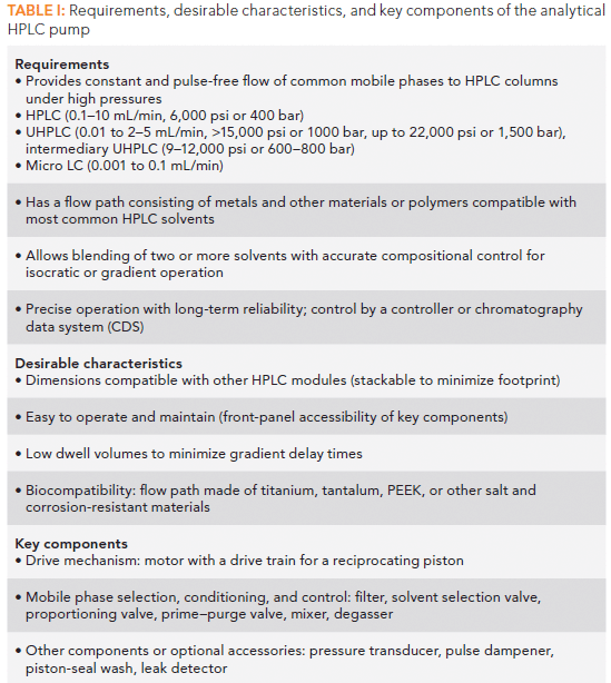
Table I: Requirements, desirable characteristics, and key components of the analytical HPLC pump
Brief Historical Perspectives
There are numerous historical accounts of HPLC and its instrumental development (3,4). The following are brief highlights of the development of different types of pumps, leading to the dual-piston renditions commonly in use today.
Constant Pressure Pumps
Perhaps the simplest way to pump liquids into a column is to pressurize the mobile phase reservoir with a gas, such as nitrogen. The fundamental problem with this simple constant pressure approach is that the flow rate will be dependent on the flow resistance of the column. As pressure drop changes, the flow rate would be barely controllable, leading to unpredictable retention times. Also, the gas solubility in the solvents and the control for accurate blending can be fundamental issues.
Constant Flow Pumps
Constant flow rate pumps have been the standard approach since the debut of the first commercial HPLC system in the 1960s. This is important because most chromatograms use detector signals plotted against the x-axis in time (as minutes) to yield peak retention times for analyte identification. Though peak retention volume (VR) is the more inherent property in the chromatographic theory for solute retention, time has established itself as the preferred x-axis coordinate in chromatography, because it can be measured more easily and precisely than volume. Since VR is equal to retention time (tr) multiplied by flow rate (F), F must remain constant throughout the chromatographic run for proper evaluation and quantitation of chromatographic peak area versus time.
Although the delivery of a constant flow under isocratic conditions and low pressures can be easily accomplished by a direct displacement pumping mechanism, it is considerably more difficult to deliver a variety of mixed solvents with changing composition at high pressures accurately. Solvents have different coefficients of compressibility and thermal expansion coefficients, which should be compensated for to obtain reproducible HPLC separations across a variety of HPLC platforms.
Syringe Pumps
Many early HPLC pumps in the 1960s and 1970s were syringe pumps (such as the Varian 8500 Dual Syringe Pump System in 1975). The syringe pump is ideally suited for the generation of a perfectly constant flow without pulsation against a constant load. The gradient can be formed by using two or three syringe pumps. The big disadvantages are the cumbersome screw-driven syringe mechanisms (fill volumes of 250–1000 mL) needed to provide common analytical flow rates for each chromatographic run, and the painfully slow syringe retraction process before each sample injection. Today, syringe pumps are rarely used, except for micro or nano HPLC instruments (Eksigent nanoLC 400), and portable units (Axcend Focus LC) where the smaller flow rates allow for more compact pump designs, or post-column derivatization.
Single-Piston Reciprocating Pumps
The single-piston reciprocating pump was the mainstay in HPLC solvent delivery using piston mechanisms in its early days. Its strengths are compactness, low-cost, and continuous delivery, while the key weakness is the pulsed flow caused by the piston recharge cycle.
Figure 1a shows a schematic of the simple reciprocating pump using a single-piston mechanism. Here, a motorized cam drives a piston within a chamber or cylinder in the pump head to deliver a solvent through a set of inlet and outlet check valves. The typical piston volume was ~100 µL for most HPLC pumps. Because only the inward piston stroke delivers the liquid, a pulse damper or other means is needed to reduce flow fluctuations. All components in the fluidic path of the pumps are made from inert materials (for example, stainless steel pump heads, ruby balls with sapphire seats in check valves, sapphire or ceramic pistons, or fluorocarbon pump seals). This popular low-cost reciprocating pump design (Milton Roy Mini-pump and Altex110A in the 1970s) has undergone numerous enhancements to improve performance. Nevertheless, the deficiencies of the single-piston mechanism quickly led to the development of the dual-piston pump, which became the dominant design starting in the 1980s.
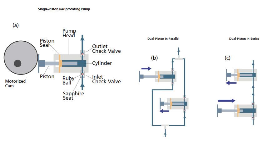
Figure 1: Schematic diagrams: (a) single-piston reciprocating pump driven by a motor with a circular cam; (b) dual-piston in-parallel format with two pistons operating 180 degrees out of phase; (c) dual-piston in-series format with a primary (first) piston and a secondary (accumulator) piston, shown in the primary stroke phase. Note: the primary piston provides the flow to fill up the secondary cylinder with a retreating secondary piston, and at the same time the system is flowing.
Dual-Piston Pumps
Dual-piston pumps are the most popular mechanisms in use today, and are available as dual-piston in-parallel or dual-piston in-series formats. A detailed explanation of these two formats can be found elsewhere (7), but we provide our overview below.
Dual-Piston In-Parallel Pumps
Dual-piston in-parallel pumps often use a single motor with a cam driving two pistons (180 degrees out of phase) delivering a combined flow with significantly less pulsation (Figure 1b), such as the Perkin-Elmer Series 3 in the late 1970s. The same can be accomplished by a single motor with a gear system that drives two pump heads, as in the compact Waters M6000 pump (1972). The M6000 quickly became the gold standard in HPLC pumps at that time.
The dual-piston in-parallel design has become less common in the analytical pumps market after the popularization of the dual-piston in-series format. Nevertheless, it was revived in some UHPLC pumps, such as the Shimadzu AD models and the Thermo Vanquish pumps (2014).
Dual-piston In-Series Pumps
The dual-piston in-series mechanism (Figure 1c) has two pistons that can be driven by one or two separate independent motors. The first piston (often called the primary piston) is used to deliver a single or mixed solvent to the second piston (the high-pressure piston, sometimes called the secondary piston or accumulator). The first piston can have the same or a slightly larger displacement volume than the second piston. The refinement of the movement of the two pistons during the piston switching phase, when the solvent is passed from the first chamber into the second piston chamber, is particularly challenging to allow compensations of compressibility and thermal expansion by elaborate piston control algorithms and pressure sensorics. This configuration is capable of delivering mobile phases with highly accurate compositional control and less pulsation. This configuration was adopted by most popular HPLC and UHPLC systems (such as Agilent's 1100, 1200, 1260 with single motor design, Agilent 1290 with independent piston drives, and Waters Alliance and Acquity UPLC instruments with independent piston drives). This format is popular in low-pressure mixing quaternary pumps.
High-Pressure and Low-Pressure Mixing Systems
Pumps are categorized as high-pressure mixing (mostly binary pumps) or low-pressure mixing systems (all quaternary pumps), based on the way two or more solvents are mixed in preblending isocratic or gradient operation.
High-Pressure Mixing Pumps
In high-pressure mixing systems, two (and occasionally three) separate high-pressure pump units are used to mix solvents at high pressures downstream of the pump units (Figure 2a). A coordinated flow rate control of each pump is used to generate different isocratic blending or gradient profiles. A mixer is commonly used to ensure adequate mixing of the solvents for most applications. The volume and the design of the mixer can be tuned to have the ideal compromise between homogeneity of the blended solvents blend and dwell volume. Binary pumps generally cost more than their quaternary counterparts, but have the advantage of lower dwell volumes (2). Solvent selection valves are used to enable selection of additional different solvents for unattended method or application switching. Typically, one solvent from up to three solvent reservoirs (Thermo Vanquish) can be selected for each line, though only binary solvent mixtures can be delivered at one time. Most early UHPLC systems use binary pumps to reduce dwell volumes and for better compositional accuracy performance (6,8).
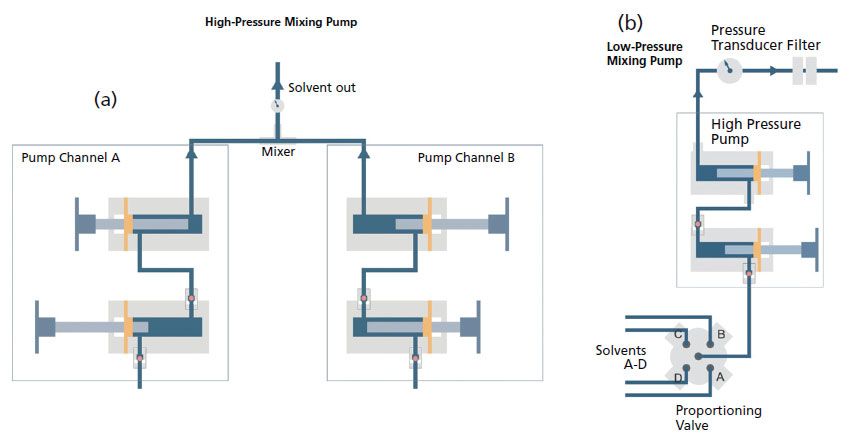
Figure 2: Schematic diagrams: (a) high-pressure mixing quaternary pump; (b) low-pressure mixing binary pump.
Low-Pressure Mixing Pumps
Spectra-Physics was likely the company that first introduced a low-pressure mixing system (ternary) in the late 1970s (the SP8100). A quaternary HPLC system using a dual-piston in-series pump was introduced by Perkin-Elmer (Series 4, 1983). Today, all quaternary pumps use a low-pressure mixing design, where a single pump unit draws mobile phases from a four-port proportioning valve, as shown in Figure 2b. The pump's microprocessor controls the solvent composition of each intake piston stroke by the timed opening of each solvent port.
The first piston of a dual-piston in-series pump unit withdraws the solvents to be mixed from the separate lines under low pressure, while the second piston pushes an accurate flow rate under high-pressure into the system. Typically, solvent blending occurs inside the first piston cylinder, though a mixer can be installed right after the proportioning valve in some designs (such as the Agilent 1290 quaternary pump). All the internal components in the fluidic path (both cylinders with their dead volumes, pulse damper if present, purge valve, in-line filter, and pressure transducer) contribute to the internal liquid hold-up or dwell volumes (2,8). However, the major advantages of low-pressure mixing pumps are the inherent simplicity and lower cost, because only one high-pressure pump unit is needed.
The low-pressure mixing quaternary pump has become the de facto standard pump for many laboratories in method development and routine analysis, as it can automatically blend up to four solvents. In comparison with the binary pump, the quaternary pump is less expensive, generally has a larger dwell volume, and has less compositional accuracy, resulting in reduced retention time precision.
Still, another example of the low-pressure mixing concept was found in the HP 1090 instruments introduced in 1983. The HP 1090 PV5 had a single channel low-pressure metering pump with a proportioning valve connected to its inlet. The desired composition was generated by the proportioning valve, and the flow from the metering pump was provided to a membrane booster pump, which pressurized it and delivered it to the system at up to 400 bar. The HP1090 DR5 had a set of three metering pumps, which delivered the desired composition by continuous parallel metering of up to three solvents. The composite flow was then boosted by the high-pressure membrane booster pump. The booster pump operated at 10 Hz. Thus, the residual flow pulsations could be easily dampened down. The HP 1090 pumps provided excellent composition accuracy and precision as a result of complete decoupling of solvent metering and pressure generation. This concept has since been displaced from the market, due to its complexity and high manufacturing cost.
The Design of a Modern UHPLC Pump: A Case Study
To illustrate the application of concepts and modern pump technologies, we use the Agilent 1290 Infinity II High Speed Pump, a binary high-pressure mixing pump (19,000 psi, 1300 bar), as an example of design rationale and performance characteristics (9).
Figure 3 shows a schematic diagram of the various key components of this pump. Although the design strategy of each manufacturer may vary significantly, the goal is to provide a cost-effective system that delivers accurate pulse-free flow rates in a range to support analytical-scale isocratic and gradient analysis.
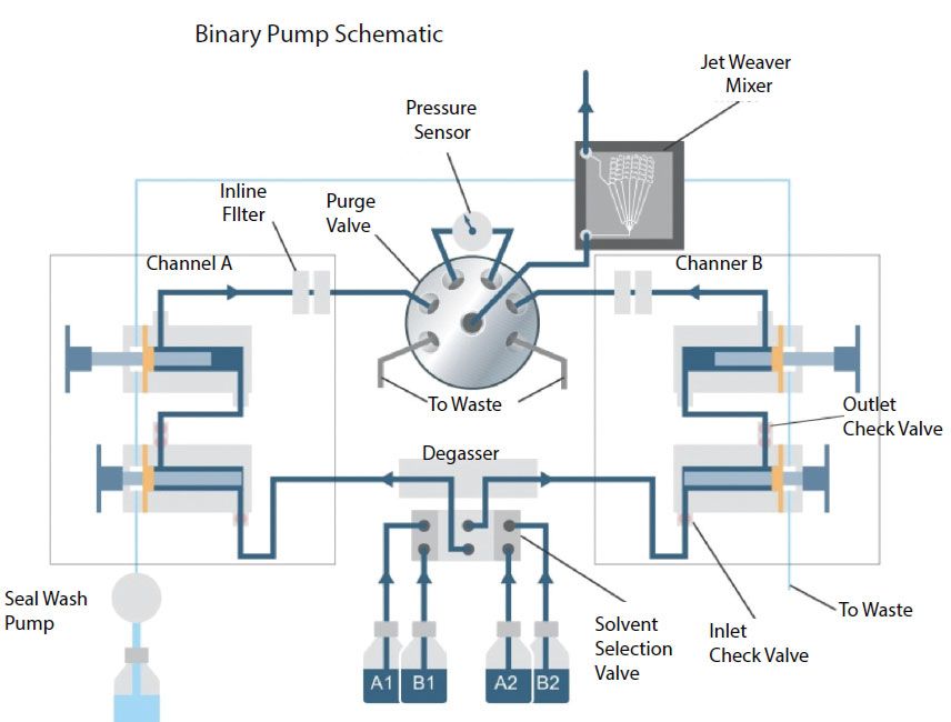
Figure 3: Schematic diagram of key components and flow path of a high speed UHPLC binary pump.
This particular pump has a solvent selection valve to allow the selection of two solvents for each pump channel (A1, A2, B1, B2). Like most modern pumps, a solvent vacuum degasser (1.5 mL per channel) is built into the system, to prevent outgassing of air bubbles in the system. The binary pump has two dual-piston in-series channels; each has two pump heads and pistons driven by separate drive mechanisms. Each solvent identity can be named in the HPLC method, allowing the system to perform compensation of solvent compressibility, based on an internal or user-loaded solvent description table. Although the ZrO2-based ceramic piston has a 100 µL-volume, the variable stroke feature allows the use of smaller stroke volumes (5–100 µL) to improve low flow performance and the use of smaller mixers.
The solvent flow from each channel passes through an in-line filter before entering an automated purge valve and a pressure sensor (transducer), and then a mixer. The mixer assembly includes two mixer units, and the user can select a mixer of 35 or 100 µL volume during installation or by re-plumbing the mixer.
Dwell volumes are important in UHPLC because of the use of smaller-diameter columns at lower flow rates. Conventional HPLC systems have dwell volumes around 1 mL or even more, which translates to a gradient delay time of 2 min at 0.5 mL/min or 5 min at 0.2 mL/min. Thus, systems based on binary high-pressure mixing pumps with reduced dwell volumes of 0.2–0.5 mL or less, depending on the pump's dwell volume and contributions of other system components, such as autosampler, are preferred for the high-throughput screening or low-flow applications.
System dwell volume can be measured by replacing the column with a zero-dead-volume union and measuring the gradient profile with a UV detector, as shown in Figure 4. Although having a small mixer is desirable for reducing dwell volumes, a larger mixer may be required for better mixing efficiency in high-sensitivity UV analysis (9,10). The volume of the mixer for acceptable mixing is dependent on the pump performance, especially on the magnitude and frequency of composition pulsations, produced by the pump. For the Agilent 1290 Infinity II High Speed Pump, the larger 100-µL mixer is well suited for most applications. If minimized gradient delay is required for high throughput or at low flow rates, the 35-µL mixer is useful. For especially critical applications (such as using trifluoroacetic acid [TFA] as an eluent additive, and striving for minimized UV-baseline noise) an even larger mixer with 380 µL volume is optionally available (9).
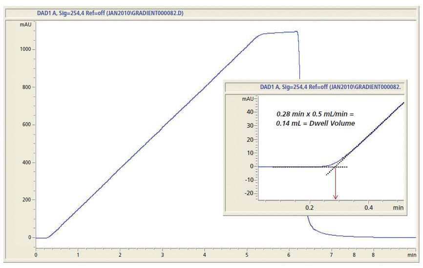
Figure 4: Gradient profile trace using an ultraviolet (UV) detector and running a 5-min gradient for the measurement of the dwell volume of a UHPLC system with a high-speed pump with a 35-uL mixer. An expanded scale insert shows the interception point at 0.28 min. of the extrapolation gradient trace with the baseline. This time point translates to a dwell volume of 0.14 mL or 140 µL (2) for the system and comprises the delay volume within the pump (mostly the mixer) and the volume of the flow path in the autosampler. The operating conditions are: mobile phase: A1 is water, and B1 is water with 0.6% acetone; solvent prog: 0 -100% B in 5 min.; flow rate: 0.5 mL/min; detection: 254 nm, 80 Hz.
The compositional accuracy of the pump can be verified by running step gradient profiles (for example, in 10% composition steps over the entire specified composition range and in finer steps in the extremes, near 0 or 100% B) with the mobile phase B (MPB) spiked with a chromophoric compound such as acetone or caffeine. Test results from comparing a binary pump to a quaternary counterpart is available elsewhere (11). A step gradient or a similar test is often included in operational qualification or system calibration procedures (12).
Other Desirable Characteristics for Modern HPLC Pumps
Other desirable characteristics for modern HPLC pumps include appearance, compactness, and dimensional compatibility to other system modules, ease of operation and maintenance, and biocompatibility for use with mobile phases with high-salt content.
Having a small system footprint is becoming important in today's laboratories, where bench space is at a premium. For modular HPLC systems, a similarity in the dimension of all modules for "stackability" is an expected attribute. Compactness is also desirable for built-in pump modules inside integrated systems (2).
Ease of operation and maintenance is another much sought after attribute. Front-panel accessibility of key components (purge valve, pump heads, and check valves) is a standard feature for most pumps. Many can be controlled by a front panel keypad or CDS. Many UHPLC pumps are equipped with automated prime and purge valves with direct draining to waste receptacles, which can be controlled and operated remotely.
For ion-exchange or hydrophobic interaction chromatography of biopharmaceuticals, titanium, or other alloy-based biocompatible systems with higher corrosion resistance to high-salt mobile phases, are often preferred. Because rinsing columns with basic solvents is also common in these applications, construction materials compatible with high pH applications (such as a piston seal) are often required. For ion chromatography (IC) systems, the use of metal-free materials is preferred. Many IC systems are poly-ether-ether-ketone (PEEK) based, with pressure ratings limited to about 5000 psi or 350 bar.
Best Practices in Pump Operation, Troubleshooting, and Maintenance
Best practices in HPLC operation, maintenance, and troubleshooting have been described in detail in books (2,13–14), journal articles (15), and manuals or publications from manufacturers (9,16). A summary of these practice for HPLC and UHPLC pumps is included here as a brief reference guide.
Mobile-Phase Selection and Preparation
A recent article was published on modern trends, and best practices in mobile phase selection in reversed-phase chromatography (17), and a summary table is included here in Table II. The reader is referred to the original article for more details.
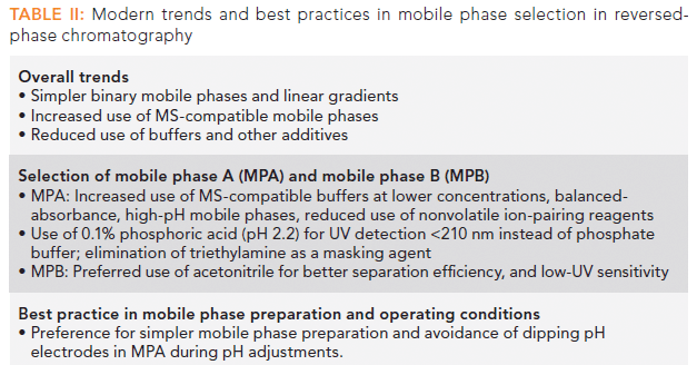
Table II: Modern trends and best practices in mobile phase selection in reversed-phase chromatography
Pump Operation and Troubleshooting Guide
The user should read the pump manual and follow the manufacturer's instructions carefully. Here are some general guidelines for HPLC or UHPLC pump operation (2):
1. Place solvent line sinkers (inlet solvent filters provided by the pump vendor) into the mobile phase in solvent reservoirs; be sure to cap the reservoirs to minimize atmospheric contaminations or evaporation.
2. In general, the degasser should be left on, and all solvent lines including the unused ones should be filled with solvents.
3. If the solvent line is "dry," perform "dry" primes by opening the manual prime and purge valve, and draw out 10 mL from each solvent line using a syringe. For pumps with an automated prime and purge valve, follow vendors' instructions. Perform wet prime for 2–5 min at high flow rates (such as 4 mL/min) daily to purge solvent lines, and when changing mobile phases.
4. Purge the column with a "strong" solvent for 1–3 min before equilibrating the column at the initial mobile phase condition. Watch for a steady pressure with minimum pulsation (<1%), or check for other criteria for proper pump operation as recommended by the vendor. Check that there is a flat baseline from UV detectors (<0.05 mAU). Excessive pressure pulsation often means a trapped air bubble in the pump head (or a faulty check valve). Follow the vendor's recommendations to fix this issue, such as by wet priming with acetonitrile or methanol. Replace the check valve if pump pulsation persists.
5. Periodic UV baseline perturbations synchronous to the pump stroke are often observed due to insufficient mixing (10). The use of a larger mixer is often the solution.
6. Program the pump to purge the column with strong solvents (such as acetonitrile or methanol), and shut down the pump after the sample sequence is complete.
Cautions When Using Buffered Mobile Phases:
7. Do not let buffers sit in the HPLC system, due to the danger of precipitation. Flush buffers from column and system with water or low organic mix, such as 10% methanol in water, depending on your application.
8. Using phosphate buffer is particularly problematic, because it may be immiscible or precipitate with acetonitrile. Use a lower concentration of phosphate buffer (<20 mM) and 85% or less acetonitrile:water as MPB, if possible (17).
9. Use the piston seal wash feature to wash the back of the piston according to the recommendations of the pump vendor, especially when running mobile phases with acidic, basic or non-volatile additives.
Pump Maintenance
In addition to adopting best practice in pump operation, periodic preventive maintenance to replace consumable parts in a preventive maintenance program is the general rule in most laboratories. Preventive maintenance is typically performed by the manufacturer's service specialist or internal metrologists. The laboratory user should stock some key spare parts and learn how to do some simple maintenance tasks.
Maintenance Procedures That Can Be Performed by the User
Although the details of maintenance procedures differ from vendor to vendor, and the user guides should generally be followed, there are some maintenance procedures common for all pumps that can usually be performed by the user. These include replacement of solvent filters (sinkers), in-line filters, check valves, and in some cases piston seals.
- There are usually several filters along the solvent flow path. They are consumables and should be replaced regularly and if getting clogged. The solvent inlet filters (sinkers), as well as high pressure inline filters, can get clogged prematurely when using insufficiently pure solvents, when not keeping solvents dust-free, or when letting "nutritious" solvents like phosphate, acetate, or ammonium buffers with low organic content stay for a longer time, especially under light conditions (use amber bottles to prevent algae growth). The symptom for inlet filter clogging is unstable pump flow or gas bubble formation in the inlet tubing. A simple check procedure for nontoxic solvents might be to open the line and let the solvent siphon down the tube. If the solvent does not siphon down or is flowing only slowly, like a droplet every couple of seconds, the inlet filter probably needs to be replaced. In the case algae or bacteria growth is recognized as a possible reason, it is a good idea to exchange the solvent bottle and inlet tubing altogether, and even to flush the pump with a disinfecting solvent such as 70% isopropanol. Inline filters on the high-pressure side can, in rare cases, also get clogged due to piston seals wear.
- A usual symptom of high-pressure filter clogging is an unexplained operating pressure increase in the system and a significant pressure reading when the pump outlet is open, even with a moderate flow (either in purge operation or when the pump outlet is disconnected from the system). The exchange procedure for filters is usually very easy.
- Most vendors offer the users a procedure to exchange piston seals in the pump heads by themselves. Though this operation often does not feel complicated, it is important to keep in mind that the tightness of piston seals is decisive for leak-free pump operation and thus for flow and composition accuracy and precision. Therefore, the vendor's recommendations must be strictly followed. Besides, it is important to replace the seals only in a clean environment, and to only use non-scratching tools, to avoid damaging the surfaces of the pump head that are in contact with the piston seal. When replacing the seals, the user might also clean the pistons and inspect the seal seats in the pump heads, as well as the piston surface for scratches or damages. It is important that, though pistons and other pump head parts are not qualified as consumables, they are usually not designed for lifetime operation, are prone to wear, and might require replacement when scratches or damage are recognized on the seal-contact areas.
- The seal wash system should be fed with fresh seal wash solvent according to the vendor's recommendations, and it should be inspected regularly to verify its proper operation, unless the system is equipped with a seal-wash monitoring sensor.
- Check valves can usually be replaced by the user in most systems. Some vendors offer even tool-free replaceable valves. A check valve failure is often manifested by sporadic pressure drops in the system, or by the inability of the pump to build up high pressure at all (given that the inlet filter and tubing are not clogged). Follow vendors recommendations to exactly pinpoint the faulty valve, and to replace it. The most common reasons for check valve failures are their mechanical contamination by particles coming from the solvents, or in some cases from the system wear, drying out of nonvolatile buffers in the pump or precipitation of solids from incompatible eluent buffers.
- When servicing the pump or any other module, always follow the prescribed tightening torques for any mounting screws, check valves, Swagelock components, or other fittings and connectors. Overtightening connectors or valves does not improve their tightness, and leads nearly inevitably to their permanent damage.
Summary
This installment provides an updated overview of the design features, performance characteristics, and best practices of operation and troubleshooting of modern HPLC pumps.
Acknowledgments
The authors thank the following colleagues for their review of the manuscript: Cornelia Vad of Agilent Technologies, Davy Guillarme of the University of Geneva, Frank Steiner of Thermo Scientific, and Giacomo Chiti of Manetti and Roberts.
References
(1) L.R. Snyder and J.J. Kirkland, Introduction to Modern Liquid Chromatography (John Wiley & Sons, Hoboken, New Jersey, 3rd Ed., 2010), Chapter 3.
(2) M.W. Dong, HPLC and UHPLC for Practicing Scientists (John Wiley & Sons, Hoboken, New Jersey, 2nd Ed., 2019), Chapters 4, 7, 8 and 11.
(3) S. Finali, P. Haddad, C. Poole, P. Schoenmakers and D. Lloyd, Eds., Milestones in the Development of Liquid Chromatography, in Liquid Chromatography (Elsevier, Amsterdam, the Netherlands, 2013), Chapter 1.
(4) C. H. Arnaud, Chem. & Eng. News 94(24), 29–35 (2016).
(5) D. Guillarme and M. W. Dong, Eds. Trends in Anal. Chem. 63, 1–188 (2014).
(6) J. De Vos, K. Broeckhoven and S. Eeltink, Anal. Chem. 88, 262 (2016).
(7) J. W. Dolan, LCGC North Am. 34(5), 342–329 (2016).
(8) M.W. Dong, LCGC North Am. 35(6), 374–381 (2017).
(9) Agilent 1290 Infinity Binary Pump: User Manual, G4220-90006 Rev. E, Agilent Technologies, Waldbronn, Germany, 2015.
(10) M.W. Dong, LCGC North Am. 35(11), 818–823 (2017).
(11) A. G. Huesgen, Agilent 1290 Infinity Quaternary Pump, Technical Overview, 5991-1193EN, Agilent Technologies, 2012.
(12) S. Ahuja and M.W. Dong, Eds., Handbook of Pharmaceutical Analysis by HPLC (Elsevier, Amsterdam, the Netherlands, 2005) Chapter 11.
(13) J. Dolan and L.R. Snyder, Troubleshooting LC Systems (Humana Press, Totowa, New Jersey, 1989).
(14) P.C. Sadek, Troubleshooting HPLC Systems: A Bench Manual (John Wiley & Sons, New York, New York,2000).
(15) J. Dolan, "HPLC Troubleshooting," Columns in LCGC North Amer. 1983-2016.
(16) U. Neue, HPLC Troubleshooting Guide, Waters Applications Notes, 720000181EN, Waters Corp., Milford, Massachusetts, 2002.
(17) M.W. Dong and B.E. Boyes, LCGC North Am. 36(10), 752–767 (2018).
ABOUT THE AUTHORS
Konstantin Shoykhet

Konstantin Shoykhet is a Senior R&D Scientist at Agilent Technologies, in Waldbronn, Germany, focusing on liquid chromatography and solvent delivery. He holds a PhD in Chemistry from the University of the Saarland in the field of liquid chromatography and capillary electrophoresis.
Ken Broeckhoven

Ken Broeckhoven an Associate Professor at the Vrije University of Brussel in the departments of Chemical Engineering and Bioengineering Sciences. His research focusses on fundamental aspects of chromatography and the optimization aspects of separation performance in both liquid and supercritical fluid chromatography. He is the author of more than 60 research papers. He received 2019 LCGC Magazine's "Emerging Leader in Chromatography" Award, and is a member of the advisory editorial board of Journal of Chromatography, LCGC, and Journal of Pharmaceutical Analysis.
ABOUT THE AUTHOR
Michael W. Dong

Michael W. Dong is a principal of MWD Consulting, which provides training and consulting services in HPLC and UHPLC, method improvements, pharmaceutical analysis, and drug quality. He was formerly a Senior Scientist at Genentech, Research Fellow at Purdue Pharma, and Senior Staff Scientist at Applied Biosystems/PerkinElmer. He holds a PhD in Analytical Chemistry from City University of New York. He has more than 100 publications and a best-selling book in chromatography. He is an editorial advisory board member of LCGC North America and the Chinese American Chromatography Association. Direct correspondence to: LCGCedit@ubm.com

Polysorbate Quantification and Degradation Analysis via LC and Charged Aerosol Detection
April 9th 2025Scientists from ThermoFisher Scientific published a review article in the Journal of Chromatography A that provided an overview of HPLC analysis using charged aerosol detection can help with polysorbate quantification.
Analyzing Vitamin K1 Levels in Vegetables Eaten by Warfarin Patients Using HPLC UV–vis
April 9th 2025Research conducted by the Universitas Padjadjaran (Sumedang, Indonesia) focused on the measurement of vitamin K1 in various vegetables (specifically lettuce, cabbage, napa cabbage, and spinach) that were ingested by patients using warfarin. High performance liquid chromatography (HPLC) equipped with an ultraviolet detector set at 245 nm was used as the analytical technique.
Removing Double-Stranded RNA Impurities Using Chromatography
April 8th 2025Researchers from Agency for Science, Technology and Research in Singapore recently published a review article exploring how chromatography can be used to remove double-stranded RNA impurities during mRNA therapeutics production.


