The LCGC Blog: Solve Carryover Problems in Gas Chromatography
In this instalment of the LCGC Blog, solutions for carryover problem in gas chromatography (GC) are considered.
Photo Credit: Photocreo Bednarek/stock.adobe.com

In this instalment of the LCGC Blog, solutions for carryover problem in gas chromatography (GC) are considered.
Let’s first properly define carryover in the context that I’d like to discuss here. An injection is made and a chromatogram obtained. On injecting a “blank” as the next injection, one or more of the components of the previous injection appear in the “blank” chromatogram.
This definition needs further clarification:
1. Blank injection can be a pure solvent (or solvent mixture), or, if contamination of the solvent(s) is suspected, then the “blank” may be an injection of air (for example, a 0 mL injection).
2. While the “blank” may contain components of the previous injection, depending upon the solvent used, one may observe carryover from several injections previously. Here, I refer to the often puzzling issue where several injections are made without evidence of carryover then “out of the blue” a component will appear in the chromatogram that was present in a sample from several injections ago. I will explain this more fully subsequently.

In summary, carryover in this context is related to the instrument rather than solvent contamination.
However, while the contamination may not arise from the sample solvent injected, the nature of the solvents used within the system are intrinsically linked to the majority of carryover problems in gas chromatography (GC). So, why is this and what can be done about it?
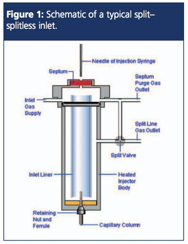
To help with the visualization of the concepts discussed below, Figure 1 is a schematic of a typical split–splitless inlet with the various gas flows noted.
Injection Volume Related Carryover
In split–splitless injection, the injected liquid expands rapidly to form a gas plasma containing our analytes, hopefully also in the gas phase. The space within the inlet, into which this expansion occurs, is primarily dependent upon the internal volume of the inlet liner used, and the available volume may vary significantly depending upon the design of the liner used. Most manufacturers will publish the internal volume of their various liner styles or this information will be available through one of the many online vapour volume calculators: CHROMacademy Calculator (1), Agilent GC Calculator (2), and Restek Backflash Calculator (3).
The inlet pressure (determined by the total flow into the inlet), inlet temperature, and sample volume injected all influence the volume of gas created from the injected sample. If the volume of gas created by the sample exceeds the available volume within the liner, gas may overflow from the liner and will typically end up in the septum purge and carrier gas lines (yes, overflowing sample vapour may overcome the forward pressure of the inlet gas supply and flow back up the carrier gas inlet lines). As these lines are typically unheated, higher boiling and more polar sample components may condense and “coat” the lines. Any subsequent overloaded injection (typically known as “backflash”) may then flow through the unheated lines and reâsolubilize the condensed components. As the inlet pressure equalizes, or as the split line is opened in the case of splitless injection, then this re-dissolved component is drawn back into the inlet and may ultimately enter the column, therefore causing carryover.
One should note that this may not occur every time a backflash injection is made, and in some cases the polarity of the sample vapour relative to the condensed contaminant will determine how well the contaminant is re-dissolved, and therefore whether it is seen within the subsequent chromatogram. This can lead to the situation in which the contaminant may not become obvious until several injections later, if the solubility of the contaminant is not high in the intermediate injections. So, a polar contaminant may not appear in backflashed injections of, say, hexane, but may then become apparent when a backflashed injection of methanol is made several injections later. Not only is the problem of backflash rather insidious, it can also be very confusing because the appearance of the carryover may appear to be random and not apparent in the injections immediately following.
As splitless injections have inherently lower total gas pressure in the inlet (only the carrier flow is passing through the liner) and as the residence time of the sample solvent within the inlet is higher, splitless injection is considered to have a higher risk in terms of injection backflash and inlet contamination.
In order to overcome backflash issues there are three choices:
1. Use pressure pulsed injection-in which the inlet pressure (total flow into the inlet) is increased during the injection phase and then reset to the desired pressure (and column flow) post injection. In splitless injection the pressure pulse time is usually matched to the splitless time.
2. Reduce the amount injected
3. Use a small split to increase the inlet pressure during injection
Obviously choices 2 and 3 need to be evaluated against any loss in sensitivity unless the sample concentration can be increased prior to injection, whereas choice 1 will
not lead to any reduction in analytical sensitivity.
The calculators mentioned above can all be used to assess the likelihood of backflash within the inlet and therefore will help to mitigate the issue.
Contamination of the Split Line
You may have noted that the split line on your gas chromatography instrument is also unheated. So whatever issues occur with the deposition of components into the carrier and septum purge lines may also occur within the split line. However, most inlet designs have a split line lower within the inlet than the split line (Figure 1), and the sample gas typically follows a more tortuous path through the liner prior to passing out of the split line. This being said, it is perfectly possible for less volatile sample components to condense within the split line and the charcoal trap, which is also included in the split line on most instrument designs. If the concentration of this contamination is high or builds up over a period of time, it is possible for carryover to occur in a very similar fashion to the backflash injection. This can be confirmed, and indeed mitigated, by “steam cleaning the split line” with several large volume injections (typically 5 mL) of water at very high split flows. If the contamination is nonpolar, then ethyl acetate can also be injected in a similar fashion until the carryover is eliminated.
Contamination of Inlet Components
Inlet components such as the liner may become “active” over time, as a result of exposure of silanol groups on the quartz glass from which the liner is made or from any quartz wool packing within the liner or from active metal sites on the inner metal surfaces of the inlet body. This is typically associated with peak tailing phenomena for polar analytes because of unwanted secondary interactions between the analyte and the active inlet site. However, if this interaction is strong, sample components may be irreversibly adsorbed until the following injection. However, again, if the solvent used for the next injection does not readily dissolve the contaminant, the carryover may not occur until an injection of a solvent of the same polarity is made.
To avoid these issues, ensure that deactivated liners are used, avoid the use of glass wool and packing materials within the liner if possible (check the impact on analytical sensitivity and reproducibility and discrimination effects before moving to a liner with no packing), and ensure that the inlet body is regularly cleaned. Liners should be regularly replaced and should be changed as a matter of priority when carryover problems are being investigated.
Carryover from the underside of the septum can also occur if the septum purge flow is not sufficient. This gas flow is designed to flush away septum outgassing products and to avoid sample deposition on the underside of the septum. Many instrument designs have automated control of septum purge flow and so this variable is rarely considered or the flow manually measured. Septum purge flow should be manually measured as part of preventative maintenance routines.
Contamination of Autosampler Components
Finally, the syringe and wash solvents should be considered in any investigation into carryover. Contamination may be carried on the inside and outside surfaces of the syringe needle and this can be somewhat mitigated by using rapid plunger depression and very short residence times for the syringe needle within the inlet. Most manufacturers ensure that this is built into the autosampler routine, however if your instrument provides the option for “slow” or “fast” injection, be sure to choose the fast injection option, especially with splitless injection.
Further, the syringe wash solvents should be matched to the polarity of the potentially contaminating analytes. While most users match the wash solvent with the sample solvent, one needs to carefully consider the solubility–polarity of the components involved in carryover when selecting the wash solvent. Further ensure that waste solvent bottles and the bottle tops are kept clean and regularly emptied. When the autosampler offers more than one wash solvent, one should experiment with the wash solvent routine to minimize carryover-use of one solvent post injection and one solvent pre injection, or the use of both solvents in turn both before and after injection, and so on.
The number of sample washes and syringe primes prior to injection can also be optimized to reduce carryover to the minimum levels. I have known methods that will be carryover free only after five sample washes and five sample primes prior to injection.
Hopefully you will now have a more thorough understanding of the potential sources for carryover that are instrument related and that some or all of this advice will help you to overcome issues with quantitative reproducibility or contaminants in qualitative analysis.
References
- https://www.chromacademy.com/GC-Sample-Introduction-Best-Practice.html
- https://www.agilent.com/en/support/gas-chromatography/gccalculators
- http://m.restek.com/images/calcs/calc_backflash.htm
Tony Taylor is the technical director of Crawford Scientific and CHROMacademy. He comes from a pharmaceutical background and has many years research and development experience in small molecule analysis and bioanalysis using liquid chromatography (LC), GC, and hyphenated mass spectrometry (MS) techniques. Taylor is actively involved in method development within the analytical services laboratory at Crawford Scientific and continues to research in LC–MS and GC–MS methods for structural characterization. As the technical director of CHROMacademy, he has spent the past 12 years as a trainer and developing online education materials in analytical chemistry techniques.
E-mail:tony@crawfordscientific.comWebsite:www.chromatographyonline.com

Study Examines Impact of Zwitterionic Liquid Structures on Volatile Carboxylic Acid Separation in GC
March 28th 2025Iowa State University researchers evaluated imidazolium-based ZILs with sulfonate and triflimide anions to understand the influence of ZILs’ chemical structures on polar analyte separation.
Quantifying Microplastics in Meconium Samples Using Pyrolysis–GC-MS
March 26th 2025Using pyrolysis-gas chromatography and mass spectrometry, scientists from Fudan University and the Putuo District Center for Disease Control and Prevention detected and quantified microplastics in newborn stool samples.


