Fused Silica Capillary Tubing: Selecting a Cutting Method
Various techniques exist for cutting capillary tubing. In this note we revisit these methods and provide guidelines for selecting the most appropriate method.
Various techniques exist for cutting capillary tubing. In this note we revisit these methods and provide guidelines for selecting the most appropriate method.
Fused silica capillary tubing is commonly produced in long, continuous lengths. Most applications require sectioning of the capillary into lengths that appropriately match the application. For example, ferrules for fiber alignment are typically a few millimeters long. Microfluidic and flow control pieces are generally 1 to 10 cm. CE columns are often 30 to 100 cm, while GC columns can be over 100 m. The method for cutting to length must be suitably matched to the application.
The most common methods are standard cleaving, precision cleaving, laser cutting, and saw cutting; each has been discussed in detail previously (1–2). It is important to understand the impact that capillary attributes (i.e. wall thickness, i.d., and o.d.) have on potential utilization of each cutting method. This note discusses selection guidelines.
Standard Cleaving
A sharp cutting tool is used to form a small flaw in the tubing surface. Stress is applied across this flaw and the tubing cleaves (3). The preferred cutting tool is a ceramic cleaving stone. Standard cleaving is done manually, often resulting in a slightly uneven end-face.
Precision Cleaving
A diamond blade is used to induce a flaw in the tubing surface. Stress is applied across this flaw by a proprietary robotic system to cleave the tubing. These high-precision systems provide outstanding repeatability. This method generates minimal debris; resulting parts are clean. End-face quality is excellent and <1º of perpendicularity is common.
Saw Cutting
Multiple capillary segments are bouled using a proprietary polymer and then sawed to length as a group. Sawing leaves a matte end finish and generates debris; cleanliness is always a concern. Chips and cracks in the end-face are common; lapping and then polishing can improve surface quality if the capillary wall is of sufficient thickness. Saw cutting is good for producing very short parts, i.e. down to 0.5 mm.
Laser Cutting
This increasingly popular cutting technique employs a CNC multi-axis laser workstation to preform the cutting operation. End-faces are typically defect-free, with no sharp edges, chips, or cracks; less than 1 mm of polyimide is removed during processing. Sufficient thermal mass and rigidity must be present in the tubing for optimal results.
Discussion
Table I compares various cutting methods for a number of key tubing attributes and commonly requested finished product concerns. This information is a general guideline; there are many nuances to cutting capillary tubing. Not all points are addressed herein; for example, length tolerances vary depending upon the desired length and cutting method. End-face perpendicularity is highly dependent upon the tubing o.d. In many cases, best results are obtained with the polyimide coating intact. Objective items are ranked, rather than offering specific values.


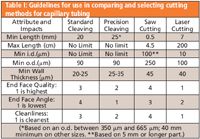
Table I: Guidelines for use in comparing and selecting cutting methods for capillary tubing
Conclusion
This note discusses four commonly used techniques for cutting capillary and provides guidelines for use in selecting a cutting method. For assistance with your specific application please contact a Polymicro technical sales specialist.
References
(1) J. Macomber, L. Begay, LCGC Application Notebook, Sept. 2003 p. 72.
(2) J. Macomber, et.al, LCGC Application Notebook, June. 2005 p. 13.
(3) "Cleaving Procedure," The Book on the Technologies of Polymicro, Polymicro Technologies LLC Publication, p. A–2, (2005).


Polymicro Technologies
A subsidiary of Molex Incorporated 18019 N 25th Ave, Phoenix, AZ 85023
tel. (602)375-4100; fax (602)375-4110
Website: www.polymicro.com


Automated Sample Preparation (ISO 20122) for MOSH/MOAH in Seasoning Oils
May 6th 2025This work presents an Automated Sample Preparation procedure for MOSH/MOAH analysis of Seasoning Oils. We compare results from a manual epoxidation procedure compliant with DIN 16995 with results based on fully automated sample preparation (epoxidation and saponification) compliant with ISO 20122. In both cases, online clean-up via activated aluminum oxide (AlOx) are used to remove interfering n-alkanes from the MOSH fraction during the HPLC run. Automated data evaluation using a dedicated software (GERSTEL ChroMOH) is presented.
Free Poster: NDSRI Risk Assessment and Trace-Level Analysis of N-Nitrosamines
April 25th 2025With increasing concern over genotoxic nitrosamine contaminants, regulatory bodies like the FDA and EMA have introduced strict guidelines following several high-profile drug recalls. This poster showcases a case study where LGC and Waters developed a UPLC/MS/MS method for quantifying trace levels of N-nitroso-sertraline in sertraline using Waters mass spectrometry and LGC reference standards.
New TRC Facility Accelerates Innovation and Delivery
April 25th 2025We’ve expanded our capabilities with a state-of-the-art, 200,000 sq ft TRC facility in Toronto, completed in 2024 and staffed by over 100 PhD- and MSc-level scientists. This investment enables the development of more innovative compounds, a broader catalogue and custom offering, and streamlined operations for faster delivery. • Our extensive range of over 100,000 high-quality research chemicals—including APIs, metabolites, and impurities in both native and stable isotope-labelled forms—provides essential tools for uncovering molecular disease mechanisms and exploring new opportunities for therapeutic intervention.