From Detector to Decision: How Does the GC Instrument Generate Your Data?
Using the flame ionization detector (FID) as an example, we explain how the detector in a GC system generates a signal and how it is processed into chromatograms, and explore modern aspects of storing and processing digital data.
Gas chromatographs today are easy to use. With modern web-based controls and data analysis, you don’t even have to be in the laboratory to run the instrument and collect the data. In this first installment on how this magic happens, we discuss signal generation and processing from a classical flame ionization detector (FID), so that you can use the data to make decisions. The fundamental operation and chemistry of signal generation in an FID is unchanged since the 1960s, yet the data are accessed, processed, and stored much more easily today. We will discuss analog signal generation in the FID using historical references, analog-to-digital conversion, and the storage and processing of digital data that happens with today’s instruments. In the future installments, we discuss how the magic of controlling today’s “smart” and remote controlled GC’s works, more detail on how the analog signal is converted to digital data for the computer, and more on best practices and tools that our data systems can do with chromatographic data.
I write this column in my socially-distanced home office on a laptop computer, wirelessly connected to the internet, along with my cell phone streaming music in the background and playing it on a Bluetooth connected wireless speaker. I cannot help but marvel at how easy these tasks have become since my first desktop computer in 1983, a TRS-80 Model III from now-defunct Radio Shack. I also cannot help but think about how far gas chromatographs and their data and control systems have come since I performed my first manual injection in 1985 with the chromatogram recorded on a strip-chart recorder. Some knowledge of electronics and circuits was necessary just to assemble and operate most instruments. In a recent blog post, Jim Grinias discusses the “lost art of electronics” in chromatography and analytical chemistry (1). He is correct in that today’s “plug and play” systems have moved much of this into the background. As a direct result of instruments becoming more versatile and easy to use, the need to modify them to suit a specific analysis is greatly reduced. We now think much more about modifying the chemistry (changing the stationary phase, sample preparation, or detector) than about modifying the instrument itself. However, the same electronic principles, and sometimes the same electronics as in the distant past, still form the heart of modern instrument control and data analysis systems.
Inside a gas chromatograph (GC), however, the chemistry and the fundamental electronics needed to produce an electrical signal at a detector when an analyte passes through it are not much different today than when most of our detectors were invented in the 1950s and 1960s. GC is unique among instrumental methods in that most of the classical detectors were invented or adapted to the specific needs of detection in GC, which, in this case, is high sensitivity and selectivity in a rapidly moving, vapor phase eluent stream. Using the flame ionization detector (FID) as an example, we will explore how the detector generates a signal, what that signal is, and how it is processed into the chromatograms and other information that is stored and provided by a modern data system. We will do this by walking through the evolution of data processing in GC from the early days to today, examining how the various components work and how they were ultimately integrated into the instrument.
A classical schematic of a flame ionization detector is shown in Figure 1, adapted from early works (2–4). There were several early designs, including single and multi-jet. Today’s FIDs use a single jet design, as seen in Figure 1. In short, the column effluent is mixed with hydrogen and air (or, in the case of some of the early work, hydrogen and nitrogen, the most common carrier gas back then), and ignited, generating a flame between two electrodes. The flame temperature of about 2000 oC is not sufficient to ionize water vapor, the product of hydrogen combustion, but is sufficient to ionize a small portion of the carbon dioxide produced by the combustion of organic compounds. The ionized CO2 present in the flame then allows the circuit to be completed and electrical current to flow. The amount of current (amperes) is proportional to the mass of CO2 generated in the flame. Variations in the chemistry of combustion reactions in the flame lead to the need to determine response factors, and provides the selectivity of the FID for organic (carbon-containing) analytes (5). A complete description of how to operate an FID can be found on LCGC’s learning platform, CHROMacademy (6). While the techniques and electronics we use to measure and analyze the signal have changed over the decades, the fundamental combustion chemistry that generates it has not changed.
Figure 1: Diagram of a classical FID showing the electrical circuit and how the flame completes the circuit and generates the current that is measured.

The electrical current produced by the FID is usually measured in picoamperes (pA) by an electrometer that may also convert the current into a voltage for output to a data system. The output of an FID is an analog signal, in which the output, an electrical current, varies continuously with the input, the mass of carbon entering the detector. This signal must be further processed in order to produce a chromatogram, perform calculations and store the data.
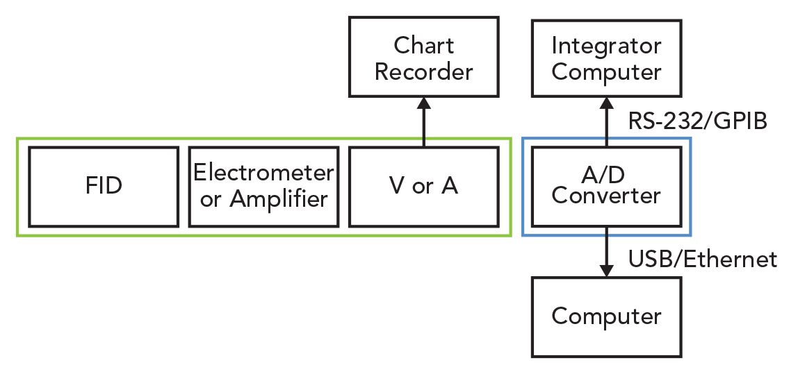
Figure 2 shows a simplified block diagram of the data processing steps in GC over the years. First, the current is amplified (think about an old stereo with an amplifier) and then may be converted to a voltage. The electrometer output (volts or amperes) is represented by the third block in the middle of Figure 2. In predigital-age GC, shown by the green box in Figure 2, the voltage was plotted against time on a continuous roll of paper using a strip-chart recorder that was connected to the electrometer by a cable. The voltage signal (y-axis) and time (x-axis) scales could be adjusted to obtain a proper appearance for the chromatogram, but there was no data storage capability. If you wanted to make the peaks appear larger or smaller to fit on scale, you usually had to rerun the sample. Quantitation was most often done using peak height (again, the scale was limited to what would fit on the paper), which was much simpler than peak area. To measure the peak area, one could count the little square blocks on the paper under the peak, carefully cut the peak out with scissors and weigh it, or use a challenging device called a planimeter (7)
Figure 2: Block diagram showing the components of a modern GC and data system. Colored boxes show the components internal to the GC as the generations of instruments have progressed. Green = 1950s to 1980s. Blue = 1980s to Present.

The analog output and strip chart recorder combination was the most common means of data collection in GC until the 1980s, when microprocessors became available in desktop or bench top computers. In the 1980s and 1990s, digital electronic integrators, specialized small computers, were commonly used for data collection and analysis. Like a strip chart recorder, these devices printed chromatograms on rolls or sheets of paper. In addition to printing out the chromatogram, the raw data could be digitized and stored for later processing or analysis in computer memory within the integrator.
To understand how analog signals are transferred to a digital electronic computer or integrator, we need some definitions of the language and standards for digital data storage and transmission. Digital signals use binary (or base-2) numbers and logic. A binary number is code for a simple switch that may be either ON (1 or one) or OFF (0 or zero). A single binary data point is called a bit. For example, when we discuss internet service provider speeds at 100 Mbps, they mean that you can transmit up to 100 megabits (100 million bits) per second. A string of eight bits is termed a byte. A byte of data can be thought of as the equivalent of a single alphanumeric character (a letter or a number). A memory card with one GB of storage space can hold one gigabyte or approximately one billion characters of information.
To standardize the use of alphanumeric characters in digital storage, nearly all computers use ASCII or the American Standard Code for Information Interchange, which provides a seven-bit representation of all of the letters, numbers, and characters on a standard United States keyboard plus representations for various control functions such as carriage returns and line feeds. When eight-bit microprocessors, such as the Z80 and 8088, the precursors to the microprocessors in today’s personal computers, were developed in the 1980s, ASCII was extended to eight bits, allowing for additional special characters. ASCII is still in use today, included as the first 128 characters in the Unicode standard that now includes over 140,000 different characters and symbols (8). The Unicode standard is how your cell phone knows which emoji is which, so your smiley face emoji does not turn into a frown (or worse) on someone else’s phone.
The second aspect of communicating between a data system and an instrument, besides having a standard code or rubric for converting letters numbers and symbols into bits and bytes, is a common standard for transferring the actual electronic signals. This is usually accomplished using a serial port on the computer. There have been many standards used over the decades, but the most common for GCs are RS-232, GPIB, USB, and Ethernet. RS-232 uses a 9- or 32-wire connector, and a ribbon cable to transfer the signals with one of the wires actually carrying the signal and the others related to a “handshake” between the devices in that both would have to trade the correct separate signals to demonstrate that they were ready to send or receive data. RS-232 is the classical serial port used in personal computers, but that port is slow by today’s standards as the single signal wire means that one bit is transferred at a time, hence the term “serial.” With the other control lines available, instrument manufacturers often modified the standard RS-232 connections to make their instrument and data system connections proprietary. GPIB, or General Purpose Interface Bus (also called HPIB, Hewlett Packard Interface Bus and IEEE-488) took serial communications one step further, with eight signal lines, allowing the transfer of a byte of data instead of a bit at one time. In the 1980s and 1990s, GCs with less requirements for fast data transfer often used RS-232. Meanwhile, many GC–mass spectrometry (MS) systems with need for higher throughout used GPIB. Today, most instrument communications are based on USB and Ethernet, which provide much greater speed and more strict standardization, so there is much better connectivity of instruments and data systems between vendors. While Ethernet and USB are much faster RS-232 and GPIB, the same basic principles apply. Both instrument and data system must be ready to send and receive data, the connection must be working, and the data must be transferred and stored according to industry standards.
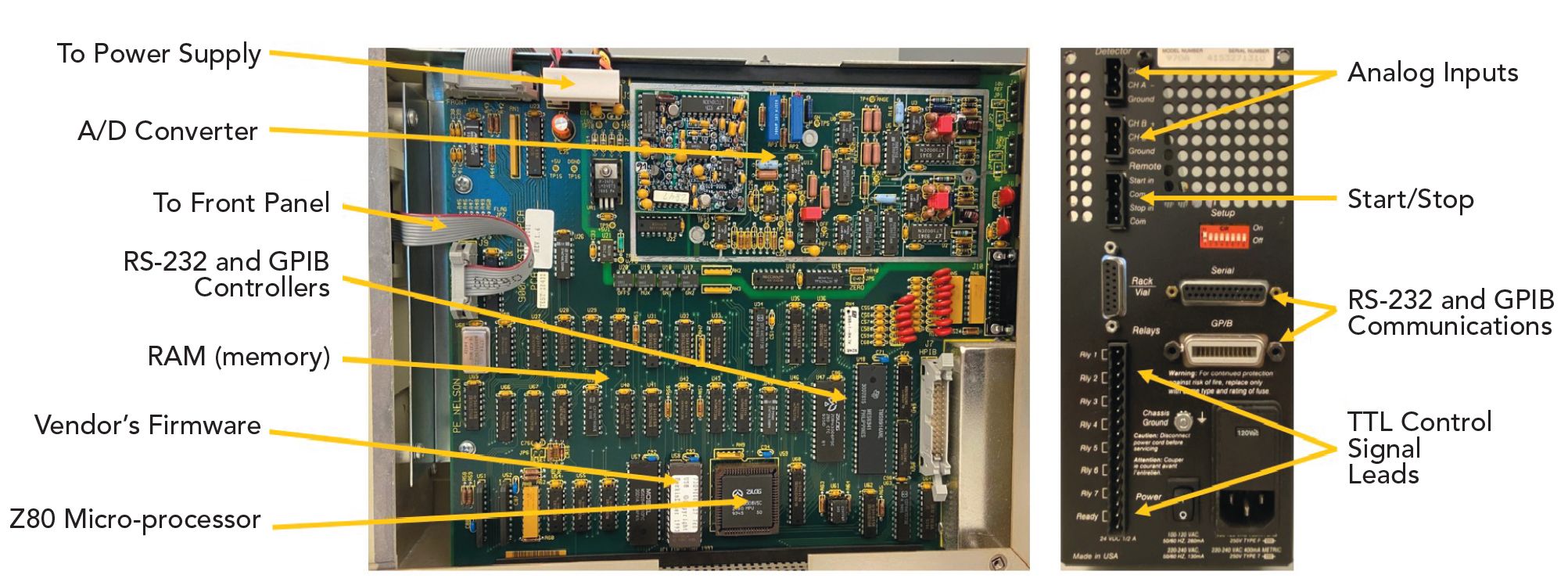
The third necessary component is an analog to digital converter that converts the analog signal into the binary digital numbers for the computer to store and process. An analog to digital converter may be included in the GC itself, or it may be added as a separate converter box. External converters were common in the 1990s and 2000s, with an example shown in Figure 3, showing a common data system interface box of 1990s vintage. The right-side image is the rear of the box where all the connections are shown. The left-side image shows a side view of the box with the cover removed to show the electronic circuitry. The back shows several types of connectors that made this interface mostly universal in that it worked with almost any GC on the market. The inputs on the top left are analog detector inputs. These could be connected directly to the analog detector outputs on the GC. Below these are connectors for remote starting and stopping the instrument, controlling an autosampler and several connectors for activating valves or switches on the GC. To the right are both types of serial connectors, RS-232 and GPIB, that connect to a personal computer data system.
Figure 3: Photographs of a 1990s-era data system interface box. Right photo: The rear of the box showing the connections to the GC and the computer. Left photo: The inside of the box showing the circuit board and the various components. (Source: Photo image courtesy of the author.)

Looking at the left side of Figure 3, we see an electronic circuit board showing the various components allowing this box to function. Some key components include the analog-to-digital converter circuitry in the top right, within the silver rectangle. The large square microprocessor in the bottom middle is a Zilog Z80 microprocessor, already mentioned in this column. This was the microprocessor used in my first computer mentioned at the beginning of the article. There were no graphics, the display was monochrome, and a separate modem allowed me to communicate with other computers over the phone lines at a whopping 300 bits per second. In the 1990s and 2000s, while no longer used in personal computers, the Z80 was commonly used in digital electronic integrators and today it is still used in many devices in the “internet of things,” such as appliances. The white chip to the left of the Z80 contains the box manufacturer’s own firmware. The large chips between the Z80 and the cable connectors on the right provide the interface between the microprocessor and the communication cables to the PC. Finally, the rest of the chips provide memory. In short, these control boxes were computers in their own right that provided an interface between the GC and the data system.
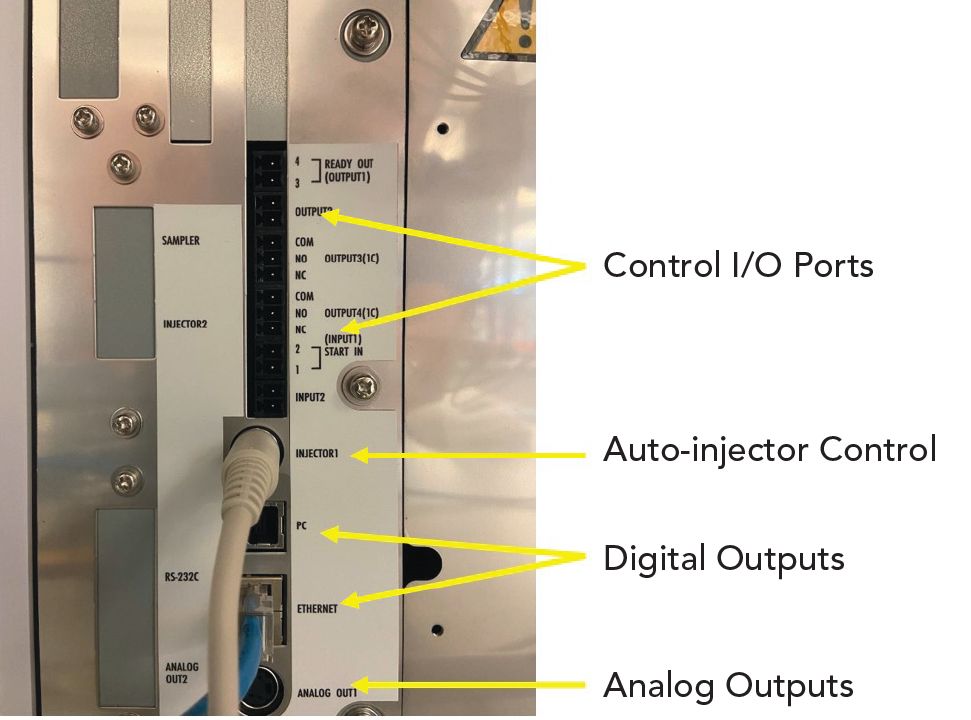
Figure 4 shows the back panel of a new GC purchased in 2019, showing the connections and capabilities that are now inside the cabinet of a modern GC. In this case, all of the functions of the control box shown in Figure 3 are now internal to the GC. Several control ports, along with input and output ports, are shown at the top of the panel. These allow the GC to send and receive signals from other devices such as a headspace sampler. This GC has a specialized port for an auto-sampler and seen with the cable attached. This port uses Ethernet to communicate with the computer, which is also seen with the cable attached. The analog to digital converter is now contained within the GC. If needed, a classical analog output is still available. Note that these functions are all very similar to those shown on the control box in Figure 3.
Figure 4: Modern USB and ethernet connectors. (Source: Photo image courtesy of the author.)

Looking back at Figures 3 and 4, we saw several additional connectors for control lines used to send and receive various commands to or from the instrument. Most commonly, these are based on transistor to transistor logic (TTL) that allows each to act as a switch that is either “on” or “off” or “1” or “0”, respectively. Each of these lines represents an opportunity for the user to activate or deactivate an electronically actuated switch or valve in the instrument or to start or stop an external device. This logic is also used to send the “start” signal between the data system and the instrument to signal the start of a run or a “stop” signal in either direction to indicate the end of a run. These lines are connected to the GC through a remote control port, such as the one shown in Figure 5, from a 1990s era GC. Each pin on the control port activates or deactivates a certain function on the GC, such as “start” and “stop.” There are multiple lines for each command to allow multiple devices to communicate. This port has lines for ready; they indicate that the instrument or device is ready to run, that it can both send and receive start signals, that it can send out information on its configuration, and ground.
Figure 5: Photograph of the remote control port on a 1990s-era GC showing connections for several basic control functions.

Conclusion
In this installment, we have discussed the basics of how a GC generates signals and transfers them to a data system to generate your data. By looking “inside the box” of a data transfer device, we have seen how the analog signal converts to a digital signal and transfers to the data system using standardized digital communications protocols. In future installments, we will look more closely at the processes for controlling the GC from the data system or from anywhere in the world and how “smart GCs” work, the process of analog to digital conversion and at best practices and tips for data systems and analysis in GC.
Remember that even with all the new technology in the foreground, a GC is still performing the same basic functions that it has done for decades: injection, separation, and detection. Fundamentally, an inlet, column oven (with a column in it), and detector have not changed. The basic digital and analog electronics that provide our ability to collect data accurately, precisely and conveniently are still there under the covers and require
our understanding.
References
- J. Grinias, The LCGC Blog, June 26, 2019, https://www.chromatographyonline.com/view/lcgc-blog-lost-art-fundamental-electronics-analytical-chemistry.
- A.B. Littlewood, Gas Chromatography, (Academic Press, London, United Kingdom, 1962), pp. 288–294.
- J. Harley, W. Nel, and V. Pretorius, Nature 181(4603), 177–178 (1958).
- I.G. McWilliam and R.A. Dewar, Nature 181(4611), 760 (1958).
- H.M. McNair, J.M. Miller, and N.H. Snow, Basic Gas Chromatography (John Wiley and Sons, Hoboken, New Jersey, 2019), pp. 124–127.
- “GC Detectors” https://www.chromacademy.com/channels/gc/instrumentation/gc-detectors/ (Accessed August, 2020).
- ”Planimeter” Wikipedia https://en.wikipedia.org/wiki/Planimeter#:~:text=A%20planimeter%2C%20also%20known%20as,an%20arbitrary%20two%2Ddimensional%20shape. (accessed August, 2020)
- Unicode, https://home.unicode.org/ (Accessed August, 2020).

Nicholas H. Snow is the Founding Endowed Professor in the Department of Chemistry and Biochemistry at Seton Hall University, and an Adjunct Professor of Medical Science. During his 30 years as a chromatographer, he has published more than 70 refereed articles and book chapters and has given more than 200 presentations and short courses. He is interested in the fundamentals and applications of separation science, especially gas chromatography, sampling, and sample preparation for chemical analysis.His research group is very active, with ongoing projects using GC, GC–MS, two-dimensional GC, and extraction methods including headspace, liquid–liquid extraction, and solid-phase microextraction. Direct correspondence to: LCGCedit@mmhgroup.com

University of Rouen-Normandy Scientists Explore Eco-Friendly Sampling Approach for GC-HRMS
April 17th 2025Root exudates—substances secreted by living plant roots—are challenging to sample, as they are typically extracted using artificial devices and can vary widely in both quantity and composition across plant species.
Sorbonne Researchers Develop Miniaturized GC Detector for VOC Analysis
April 16th 2025A team of scientists from the Paris university developed and optimized MAVERIC, a miniaturized and autonomous gas chromatography (GC) system coupled to a nano-gravimetric detector (NGD) based on a NEMS (nano-electromechanical-system) resonator.
Miniaturized GC–MS Method for BVOC Analysis of Spanish Trees
April 16th 2025University of Valladolid scientists used a miniaturized method for analyzing biogenic volatile organic compounds (BVOCs) emitted by tree species, using headspace solid-phase microextraction coupled with gas chromatography and quadrupole time-of-flight mass spectrometry (HS-SPME-GC–QTOF-MS) has been developed.


