Electromembrane Extraction with Vials of Conducting Polymer
In electromembrane extraction (EME), the target analyte is extracted from an aqueous sample across a supported liquid membrane (SLM) and analyzed using LC. Through the study presented here, we demonstrate the principles of the technique and test its performance.
The principles and experimental conditions for a new prototype electromembrane extraction (EME) device coupled with liquid chromatography (LC) are outlined and reviewed in this article. EME is a relatively recent microextraction technique based on electrokinetic migration across an oil membrane. In EME, a target analyte is extracted from an aqueous sample across a supported liquid membrane (SLM) and further analysis is accomplished by LC.
Electromembrane extraction (EME) emerged as a very new microextraction technique in 2006 (1). The principle is based on electrokinetic migration across an oil membrane (supported liquid membrane), as illustrated in Figure 1. The target analyte is extracted from aqueous sample, across the supported liquid membrane (SLM), and into an acceptor (aqueous solution). An electrical field (dc) is sustained across the SLM, and is the driving force for mass transfer. The target analyte is thus moving in the system based on electrokinetic migration, and EME is therefore used for extraction of cationic (basic) and anionic (acidic) analytes. The SLM is an organic solvent immiscible with water, immobilized and held by capillary forces in the pores of a polymeric membrane.
Figure 1: Principle of electromembrane extraction.
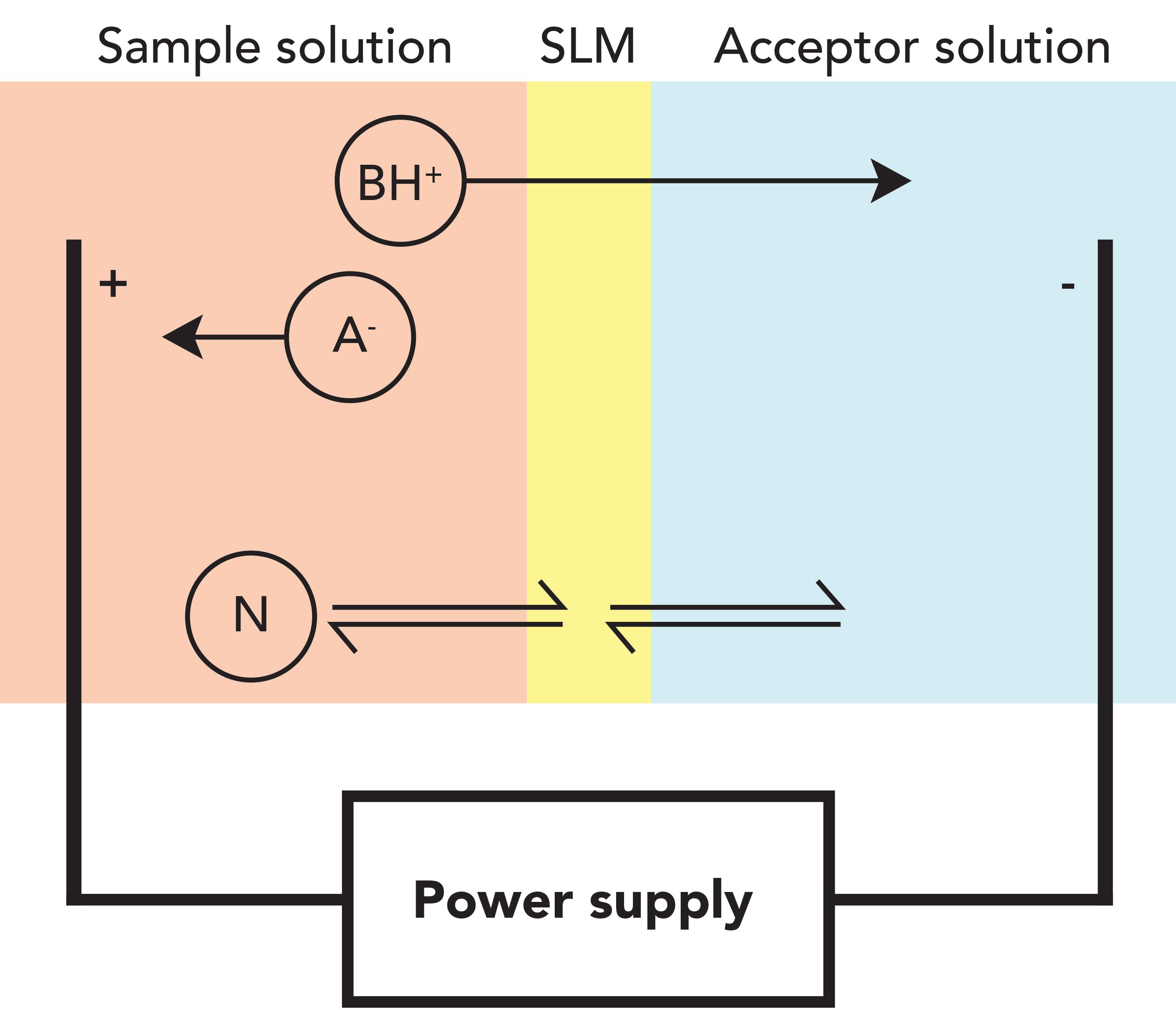
For extraction of a basic analyte, the sample is acidified and the acceptor is either acidic or neutral. In this way, the analyte is protonated; the cathode (negative electrode) is located in the acceptor, and the anode is located in the sample. For extraction of acidic analyte, the direction of the electrical field is reversed: the sample is made alkaline, and the acceptor is either alkaline or neutral. Samples can, for instance, be biological fluids, such as plasma, serum, whole blood, urine, or saliva; or different types of water samples relevant to environmental analysis.
Sample volumes in EME are typically from 0.1 to 5 mL, while acceptors are between 0.01 and 0.1 mL (10–100 µL). Because of this volume difference, EME can preconcentrate analytes. Furthermore, EME provides high selectivity. First, the organic and hydrophobic nature of the SLM prevents polar sample matrix components from entering the acceptor. Second, the electrical field prevents sample matrix components of opposite charge from entering the acceptor. Actually, selectivity in EME can be controlled based on (a) the direction of the electrical field, (b) the magnitude of the electrical field, and (c) the chemical composition of the SLM. The operational parameters controlling the selectivity are very different from those of existing extraction techniques, such as solid-phase extraction, solid-phase microextraction, and liquid–liquid extraction. In the future, analytical scientists will take advantage of these unique features.
In addition to preconcentration and efficient sample clean-up, EME is fast, the consumption of organic solvent is a few microliters per sample, and extracts are aqueous. The latter is a great advantage in combination with liquid chromatography (LC), because the acceptors can be injected directly without any solvent evaporation or reconstitution procedures. Extraction times are typically 5–10 min, and high throughput is feasible using 96-well technology (2). EME, therefore, has high-throughput potential. The extremely low consumption of organic solvent is a step in the direction of green chemistry, which will be of major concern for the next generation of analytical scientists.
Several reviews published recently give an overview of research on EME (3–6). Important EME application areas (to date) include bioanalysis of pharmaceuticals (7), analysis of food and beverages (8), environmental analysis (9), trace analysis of metals (10), and peptide analysis (11). Many substances have been extracted successfully, from small inorganic ions (12) up to peptides of about 15 amino acids (13), both positively and negatively charged substances (14), and substances in the polarity range of -5 < log P < 5 (3). High flexibility has also been demonstrated in terms of adaptability to different technical configurations. Thus, EME has been performed in conventional 1–10 mL glass vials (1), 96-well plates (2), narrow tubing and channels (15), different flow systems (16), and a variety of microchip systems (17). Very interestingly, small EME-chip devices have been developed and combined with smartphone detection (18). Although this research is in its infancy, such technologies may have very high future potential.
Coupling the Electrical Field Through Vials of Conducting Polymer
To date EME uses metallic electrodes to couple the electrical field, one serving as cathode and another as anode. Platinum wires have been preferred given their electrochemical stability and inertness. However, there are several disadvantages of using platinum wires, including:
- The expense.
- The small surface area.
- Platinum wires have to be reused.
- Platinum wires have to be cleaned between each sample, to avoid carry-over.
- Platinum can be mechanically damaged during operation.
- Platinum may complicate development of automated systems.
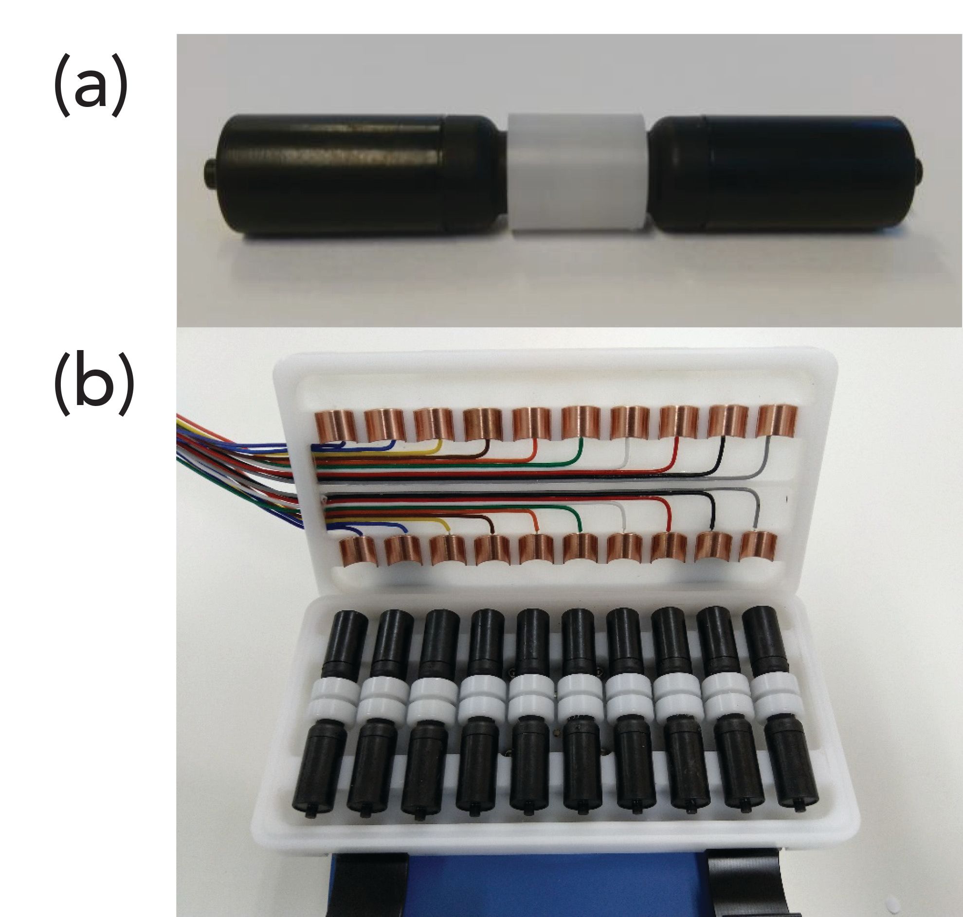
Currently, a Norwegian company is developing a prototype EME device aimed for commercialization. Figure 2 illustrates this device, based on standard 2-mL vials made from a conducting polymer. The electrical field couples using the vials as electrodes; this replaces the platinum wires. One vial is used for housing the sample, and another vial holds the acceptor. The two vials are connected by a leak-tight interface, holding a porous polypropylene filter membrane. The latter serves as a support for the SLM. Loading the SLM is performed by pipetting the exact amount of organic solvent onto the filter membrane. In 5–10 s, the organic solvent enters the entire pore volume of the filter membrane, and is immobilized there by capillary forces. An external power supply delivers the electrical field, contacting the surface of the two vials as illustrated in Figure 2. With a 10-position holder, up to 10 cartridges operate simultaneously.
Figure 2: Photo of (a) prototype cartridge and (b) 10-position holder.
In this work, we tested the prototype device for the first time using the five basic drug substances pethidine, nortriptyline, methadone, haloperidol, and loperamide as model analytes. We studied the impact of the main operational parameters, and optimized extraction conditions based on factorial design. In addition, we tested extraction performance under optimal conditions. The data are the first ones reported with commercial equipment for EME, and the first using conducting vials for coupling the electrical field.
Experimental Conditions
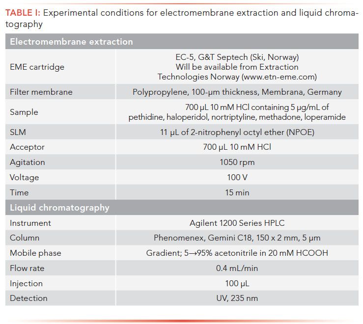
The experimental conditions for EME and LC are summarized in Table I. We used a model EC-5 cartridge with 2-mL vials for our experiments. The experimental procedure comprised the following steps:
- First, 700-µL sample and 700-µL acceptor were pipetted into separate vials.
- Next, 11 µL of 2-nitrophenyl octyl
ether (NPOE) was pipetted onto the filter membrane. - The EME cartridge was assembled by connecting the sample and acceptor vials to the interface.
- The cartridge was placed on the agitator, and power cables were connected to the vials.
- Agitation and voltage were applied simultaneously to facilitate extraction.
- After extraction, the cartridge was unassembled, and 100-µL acceptor was collected for LC.
Distribution to the Electrical Field
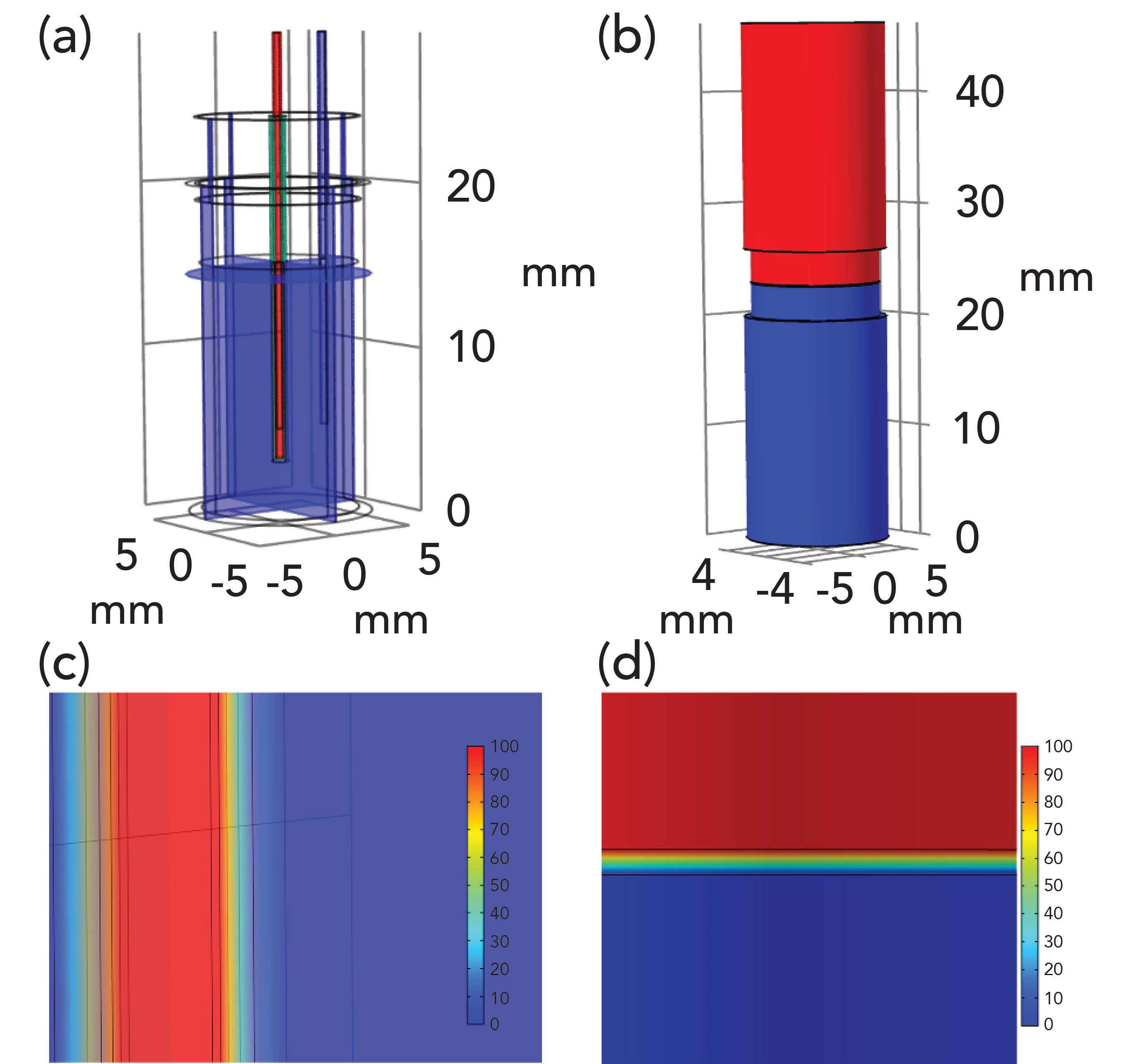
To understand the electrical properties of the prototype device, we performed a computer simulation of the electrical field distribution, and compared this with a similar exercise on a traditional EME system with platinum electrodes. We used the finite element method in Comsol Multiphysics 5.4 (COMSOL Inc., USA), and simulations are illustrated in Figure 3. The prototype device is shown in Figure 3b; the blue embodiment is the sample vial (grounded, zero V symbolized with blue) and the red one is the acceptor vial (+100 V, symbolized with red). Figure 3d shows a magnification of the SLM region. From this simulation, we found that more than 99.9 % of the voltage drop was across the 100-µm SLM. Figure 3a is a simulation of the original EME setup, where the electrical field was coupled with platinum electrodes, SLM was immobilized in the pores in the wall of a hollow fiber, and acceptor was located in the lumen of said hollow fiber (1). Also in this system, about 99.9 % of the voltage drop was across the SLM (Figure 3c). The organic SLM has a resistivity that is approximately five orders of magnitude larger than that of the aqueous sample and acceptor, and hence it totally dominates the resistance of both these systems. From the simulations, we concluded that the prototype device was very similar to the traditional EME in terms of electrical field distribution.
Figure 3: Results from Comsol Multiphysics showing voltage distribution in (a) the conventional device and (b) the new prototype, and close-ups showing the potential voltage drop in the membranes of (c) the conventional device, and (d) the new prototype.
Optimization and Effect of Operational Parameters
In a large set of extraction experiments, we conducted a comprehensive optimization of operational parameters based on factorial design. We identified (a) extraction time, (b) voltage, (c) agitation rate, (d) sample and acceptor volume, and (e) SLM volume as the key operational parameters. The average extraction recovery for the five model analytes was affected by extraction time as shown in Figure 4. Extraction time was tested between 0 and 30 min. Recovery increased rapidly with extraction time during the first 10 min, and then more gradually up to 23.7 min (Figure 4) where the system entered steady-state conditions. Voltage affected recovery as illustrated in Figure 4. At zero volt the model analytes were not extracted at all. This was consistent with theory; with pH 2.0 in the sample, the model analytes were 100% protonated (positively charged) and they were unable to partition into the SLM. However, as the voltage was turned on and gradually increased, the protonated substances penetrated the sample–SLM interface, and extraction recovery increased rapidly with increasing voltage up to approximately 80 V. Above 80 V, recovery increased slightly up to 157.6 V. Clearly, the electrical field served as driving force for extraction in the prototype device.
Figure 4: Average recovery as function of extraction time and voltage.
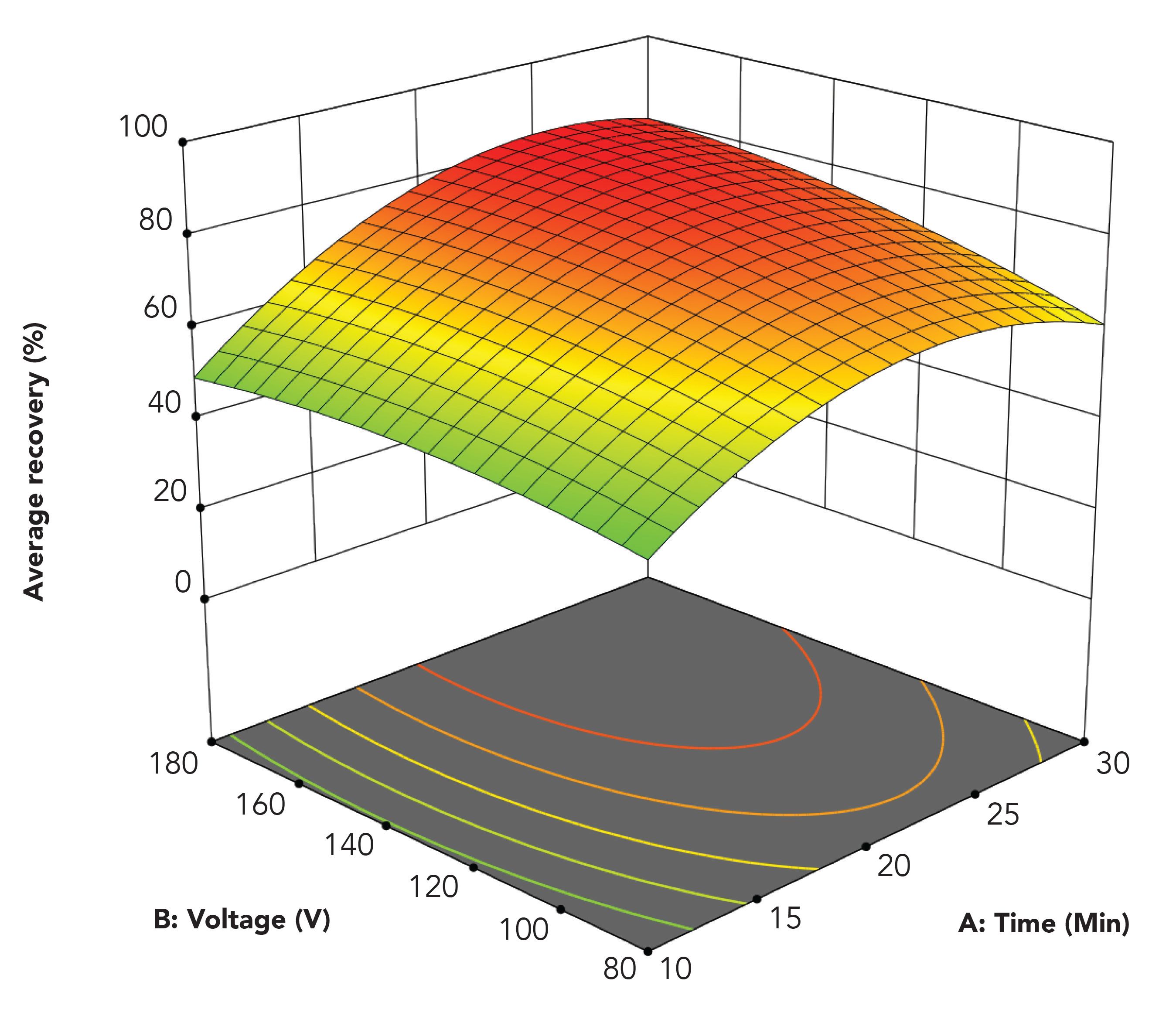
Figure 5 illustrates the optimization of agitation rate and sample and acceptor volume. Agitation rate was tested in the range from 0 to 1800 rpm. With no agitation (0 rpm), the model analytes were not extracted at all. Under these conditions, the physical contact between the three liquid phases was insufficient. On the other hand, when agitation was applied, this induced convection in the sample and extraction was promoted. As seen in Figure 5, recoveries increased with increasing agitation rate up to 1503 rpm. Above this level, recoveries decreased slightly because of issues of mechanical stability.
Figure 5: Average recovery as function of agitation rate and sample and acceptor volumes.
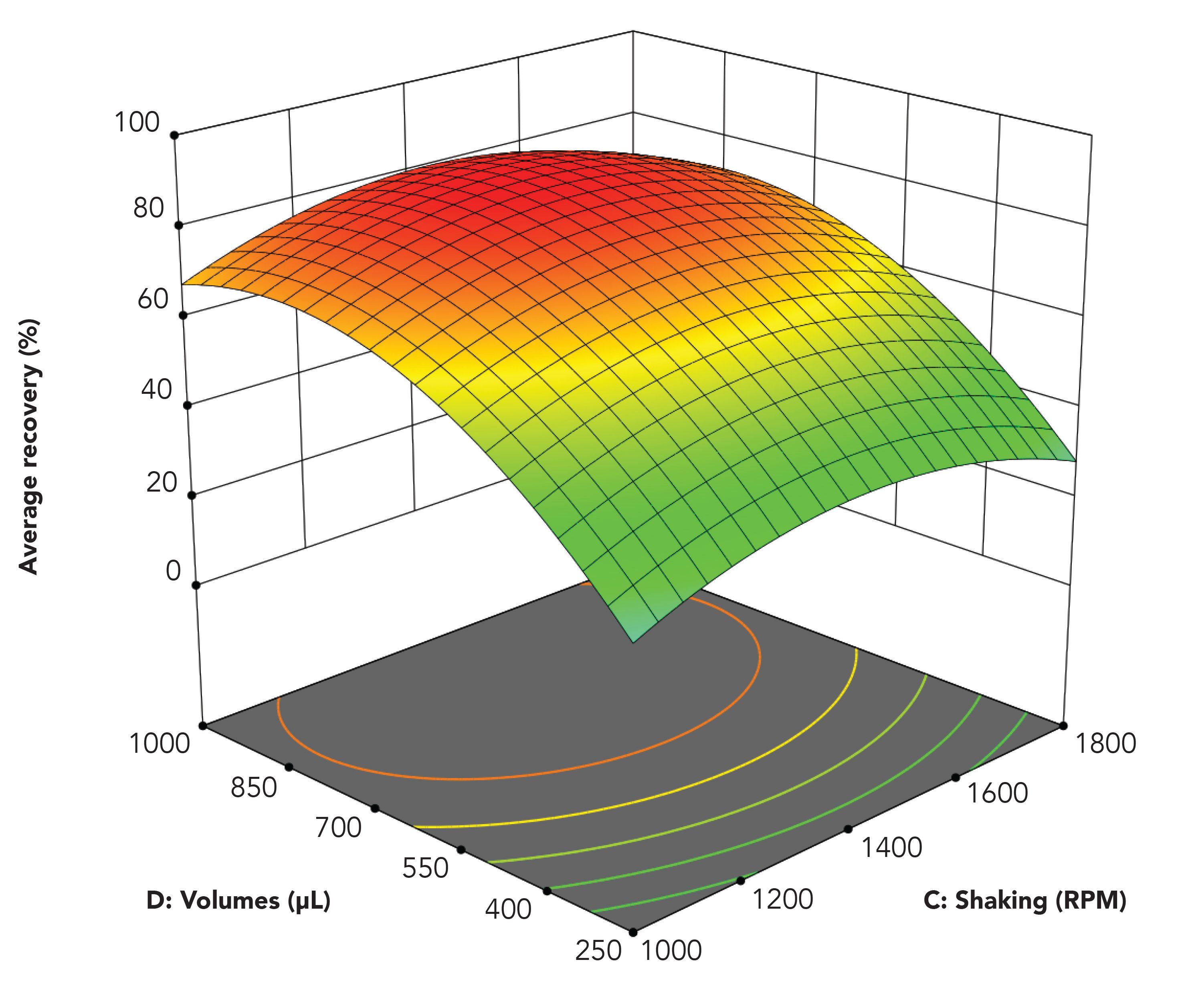
We tested sample and acceptor volumes between 250 and 1500 µL, with a 1:1 ratio in all experiments. As seen from Figure 5, recovery increased with increasing volume up to 905 µL, followed by a small decrease. With small volumes, the physical contact between the three liquid phases was limited, and this affected extraction efficiency negatively. On the other hand, when volumes exceed approximately 900 µL, convection in the sample solution was somewhat suppressed because of the high filling level.
Finally, we optimized the SLM volume. The optimal value was 12.8 µL, and we observed only minor variations of recoveries as a function of SLM volume in the range 7–22 µL. We preferred not to use more than 11–13 µL NPOE, because this volume corresponded to the maximum of solvent immobilized by the filter membrane.
The optimization data reported in Figure 4 and 5 all follow the theoretical models developed for EME (19,20), and are similar to previous experimental data reported with existing EME configurations (3). Thus, although the coupling of the electrical field is fundamentally different from that in all previous EME setups, the prototype system behaved similar to systems reported in the literature. Therefore, the scientific anchor of traditional EME apparently also applies to the prototype device, and applications and experiences from previous EME publications probably can be transferred more or less directly to the commercial device.
Extraction Recovery and RSD Under Optimal Conditions
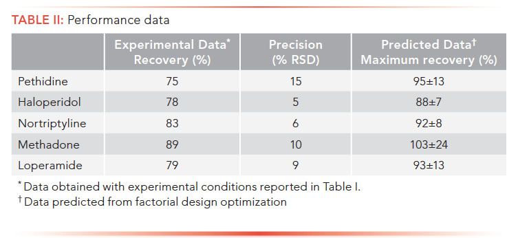
In a final set of experiments, we tested extraction recovery and precision using the experimental conditions in Table I. These are standard conditions, and deviated slightly from those found by factorial design optimization. Standard conditions were used to compare performance with literature. As seen in Table II, recoveries ranged between 75 and 89%, and precision was within 15% RSD. These data are very similar to data obtained for the same analytes, extracted under comparable conditions in other technical formats of EME (3). Thus, also in terms of extraction performance, our initial testing indicates that the prototype device should perform at levels similar to that of laboratory-built systems. From the factorial design optimization, we estimated expected recoveries for the system operated under optimal conditions (Table II). In such a case, the EME system should provide exhaustive extraction of the selected model analytes.
Conclusions
We have tested the first prototype commercial device for EME. In this device, coupling the electrical potential is through sample and acceptor vials of conducting polymer. This is a totally new idea, and replaces the use of metallic electrodes in EME. We found the prototype device to perform similarly efficient systems reported in the literature, and for the model analytes we tested, we reached exhaustive or near-exhaustive conditions. We also observed that the prototype device responded similar to existing systems upon optimization of operational parameters. Therefore, we expect previous applications and experiences can be transferred to the prototype device. With this device, we expect more activity, and scientists can generate new EME data in a standard format. This may be a major step forward in the work to establish the future “killer applications” of EME.
References
- S. Pedersen-Bjergaard and K.E. Rasmussen, J. Chromatogr. A 1109(2), 183–190 (2006).
- N. Drouin, et al., Anal. Chem. 89(12),. 6346–6350 (2017).
- N. Drouin, et al., TrAC, Trends Anal. Chem. 113, 357–363 (2019).
- C. Huang, et al., TrAC, Trends Anal. Chem., 95, 47-56 (2017).
- A. Oedit, et al., Electrophoresis 37(9), 1170–1186 (2016).
- Y. Yamini, M. Rezazadeh, and S. Seidi, TrAC, Trends Anal. Chem. 112, 264–272 (2019).
- A. Aghaei, et al., J. Sep. Sci.42(18), 3002–3008 (2019).
- F. Zarghampour, et al., J. Chromatogr. A 1556, 21–28 (2018).
- M. Villar-Navarro, et al., Anal. Bioanal. Chem. 408 (6), 1615–1621 (2016).
- W. Alahmad, et. al., Anal. Chim. Acta, 1085, 98–106 (2019).
- S.S. Hosseiny Davarani, A. Pourahadi, and P. Ghasemzadeh, Electrophoresis 40(7), 1074-1081 (2019).
- A. Slampova, V. Sindelar, and P. Kuban, Anal. Chim. Acta 950, 49–56 (2017).
- M. Balchen, et al., J. Sep. Sci. 34(2), 186–195 (2011).
- S. Asadi and S. Nojavan, Anal. Chim. Acta 923, 24–32 (2016).
- P. Kuban and P. Bocek, J. Chromatogr A 1337, 32–39 (2014).
- H.B. Dugstad, et al., Anal. Bioanal. Chem. 406(2), 421–429 (2014).
- M.R. Payan, et al., Anal. Chem. 90(17), 10417–10424 (2018).
- F. Zarghampour, et al., Anal. Meth. 12(4), 483–490 (2020).
- A. Gjelstad, K.E. Rasmussen, and S. Pedersen-Bjergaard, J. Chromatogr. A 1174, 104–111 (2007).
- K.F. Seip, H. Jensen, M. Sønsteby, A. Gjelstad, and S. Pedersen-Bjergaard, Electrophoresis 34(5), 792–799 (2013).
Milena Drobnjak, Frederik Hansen, Elisabeth Leere Øiestad and Stig Pedersen-Bjergaard are with the Department of Pharmacy at the University of Oslo, in Oslo, Norway. Pedersen-Bjergaard is also with the Department of Pharmacy at the University of Copenhagen, in Copehhagen, Denmark. Trond Løvli and Roger Trones are with 2G&T Septech, in Ski, Norway, Ørjan G. Martinsen is with the Department of Physics at the University of Oslo, in Oslo, Norway), and the Department of Clinical and Biomedical Engineering at Oslo University Hospital, in Oslo, Norway.
Douglas E. Raynie

“Sample Prep Perspectives” editor Douglas E. Raynie is a Department Head and Associate Professor at South Dakota State University. His research interests include green chemistry, alternative solvents, sample preparation, high-resolution chromatography, and bioprocessing in supercritical fluids. He earned his PhD in 1990 at Brigham Young University under the direction of Milton L. Lee. Raynie is a member of LCGC’s editorial advisory board. Direct correspondence about this column via e-mail to
LCGCedit@mjhlifesciences.com
Thermodynamic Insights into Organic Solvent Extraction for Chemical Analysis of Medical Devices
April 16th 2025A new study, published by a researcher from Chemical Characterization Solutions in Minnesota, explored a new approach for sample preparation for the chemical characterization of medical devices.
Study Explores Thin-Film Extraction of Biogenic Amines via HPLC-MS/MS
March 27th 2025Scientists from Tabriz University and the University of Tabriz explored cellulose acetate-UiO-66-COOH as an affordable coating sorbent for thin film extraction of biogenic amines from cheese and alcohol-free beverages using HPLC-MS/MS.
Multi-Step Preparative LC–MS Workflow for Peptide Purification
March 21st 2025This article introduces a multi-step preparative purification workflow for synthetic peptides using liquid chromatography–mass spectrometry (LC–MS). The process involves optimizing separation conditions, scaling-up, fractionating, and confirming purity and recovery, using a single LC–MS system. High purity and recovery rates for synthetic peptides such as parathormone (PTH) are achieved. The method allows efficient purification and accurate confirmation of peptide synthesis and is suitable for handling complex preparative purification tasks.

.png&w=3840&q=75)

.png&w=3840&q=75)


.png&w=3840&q=75)


.png&w=3840&q=75)


