Calibration Curves, Part I: To b or Not to b?
LCGC North America
This month's "LC Troubleshooting" looks at some different calibration models, how to decide if a calibration curve goes through zero, and some problems that can occur if the wrong choices are made.
There seem to be a disproportionate number of problems encountered in the concentration region near the limit of detection and lower limit of quantification with calibration curves used for liquid chromatography (LC) methods. Some of these problems relate to improperly selecting the model used for calibration. The choice of the limits of detection and quantification is an important decision that can be confusing. This month's installment of "LC Troubleshooting" is the first of a series about calibration curves. This month we will discuss some different calibration models, how to decide if a calibration curve goes through zero, and some problems that can occur if the wrong choices are made. In future columns, we will look at how to determine the lower limits of a method as well as standardization techniques: internal standardization, external standardization, and the method of standard additions. We also will look in more detail at normal errors as they relate to signal-to-noise ratio in trace analysis.

John W. Dolan
Calibration
Most LC methods are used for quantitative analysis — that is, the methods that answer the "how much is there?" question. Nearly all of these methods rely on comparison of the peak area (or less often, peak height) of a sample with that of a reference standard. To do this, we use a calibration curve (also referred to as a standard curve or sometimes "line"). The two most popular methods of calibration are external and internal standardization. In external standardization, the calibration is based upon comparing the response of the reference standard with its concentration. For internal standardization, a constant concentration of an internal standard is added to each sample and the ratio of the response of the analyte to that of the internal standard is compared with the concentration. The external-standard method is simpler and will be used for all the examples discussed here; the details of these two methods will be discussed in a future article.
There are several different ways to use a calibration curve to quantify samples. Because UV detection is used for most LC methods, and the UV detector response vs. peak area is linear over five or more orders of magnitude, we can assume linear response is possible when using a method calibration that covers a wide range of concentrations. Some other detection methods, for example, mass spectrometry (MS) or evaporative light scattering detection (ELSD), have narrower linear ranges, so a linear calibration might not be appropriate. If a UV detector is used, we assume that the well-behaved calibration curve will be linear. Linearity is defined as

where y is the response (area), x is the concentration, m is the slope of the curve, and b is the y-intercept. (Even though the relationship is linear, we still call it a curve.) When the curve goes through the origin (x = 0, y = 0), b = 0, and the curve can be expressed as

In its simplest form, equation 2 can be used for single-point calibration. In this case, one or more calibrators are injected at a single concentration and the concentration of an unknown sample is directly proportional to the response (or average response) of the calibrator or calibrators. For example, if the calibrator has a response of 100,000 area units for a 10-μL injection of a 1-μg/mL solution and the sample has a response of 95,342 area units, its concentration is (95,342/100,000) x 1 μg/mL x 0.95 μg/mL. Technically, single-point calibration should be valid whenever the standard curve behaves as in equation 2. However, it is best to inject calibration standards near the concentration of the analyte, so as to verify that the response continues to be as expected. For this reason, single-point calibration usually is reserved for samples that cluster tightly around a single concentration. A good example is a content-uniformity method to determine the concentration of a drug in a pharmaceutical product. All samples are expected to have the same concentration, so a single calibration standard is injected at the expected 100% concentration. From a practical standpoint, several calibrator injections are averaged to minimize error. Often two calibrator injections are followed by several sample injections (for example, 5–10), two more calibrators, and so forth. The four bracketing calibrators are averaged and used for calculating the concentration of the unknowns.
Another popular application of equation 2 is to methods where the expected range of sample concentrations is narrow, for example less than one order of magnitude. In this case, a two-point calibration is used. Calibrators at two concentrations that bracket the expected sample concentrations are injected. For example, a group of samples that have a specification of ±5% from the target concentration might have calibrators formulated at 90% and 110% of the expected concentration. These would be injected and used to calculate m in equation 2. Each injection would have a concentration and response: (x90, y90) and (x110, y110) for the 90% and 110% concentrations, respectively. The slope would be determined as m = (y110 – y90)/(x110 – x90). (Because the range is narrow, and will have been shown to be linear in the validation, it doesn't matter if the curve passes through the origin or not.) Now unknown samples can be injected and the concentration can be determined, using the calculated value of m as

The third common calibration technique is the multipoint calibration. As the name implies, several different points on the calibration curve are used to calculate the response vs. concentration relationship. Multipoint calibration is used for methods that cover a wide concentration range (for example, several orders of magnitude) and for methods where the calibration curve fits equation 1, but does not pass through the origin (b μ 0). For example, multipoint calibration is used for methods to determine the concentration of a drug in plasma for a pharmacokinetic studies, where concentrations of <1% of the maximum concentration (Cmax) need to be reported. Regulatory guidelines suggest using a minimum of five (1) or six (2) concentrations across the range to determine linearity of a method. Two different dilution schemes are used for selecting calibrator concentrations. For a method spanning 1–1000 ng/mL, a linear dilution might use concentrations of 1, 100, 200, 300, . . . 900, 1000 ng/mL, each differing by 100 ng/mL. A more popular scheme is an exponential dilution (sometimes improperly called "logarithmic"), where concentrations might be 1, 2, 5, 10, 20, 50, 100, 200, 500, 1000 ng/mL. For the remainder of this article, we will consider only multipoint calibration.

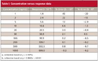
Table I: Concentration versus response data
Does the Curve Go Through Zero?
When a multipoint calibration curve is used, you must decide whether to allow b 0 (equation 1) or to force the curve through the origin (equation 2) when fitting the curve to the calibration data. Fortunately, this does not need to be an arbitrary decision, but can be based upon the regression statistics from the calibration data. As an example, we will use the data of Table I, where the response is listed for a 10-point, exponential-dilution calibration curve with a range of 1–1000 ng/mL. A linear regression of the data can be obtained from an Excel spreadsheet (Tools menu – Data Analysis – Regression). Most data system software also will perform linear regression calculations. The key regression statistics for the data of Table I are listed in Table II. The Excel nomenclature is used in Table II, with additional information added in parentheses.

Table II: Regression statistics from Excel
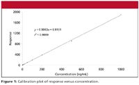
The decision to force zero or not on the calibration curve is based upon how close the calculated y-intercept is to zero. This is difficult to do visually from a plot of the response vs. concentration, as in Figure 1, but is easy (and more reliable) to do statistically. If y is less than one standard deviation (SD) away from zero, it can be assumed that this is normal variation and x = 0, y = 0 can be used in the standard curve. We can test this with the regression statistics using the standard error (SE), since we don't have enough data points to calculate the SD of y at x = 0. There are two values of SE included in the Excel data of Table II. The first is the SE for the entire curve, labeled simply "Standard Error" (1.4134). The second is the standard error of the y-intercept (0.5244), also labeled "Standard Error," but included in the information about the y-intercept at the bottom of the table. The SE for the curve is based upon the variability of the curve throughout its range, including both high and low concentrations. The SE for the y-intercept is based upon estimates of variability at the y-intercept, not the entire curve, and will always be smaller. The SE of the y-intercept (SEy) is the appropriate value to use to test if the curve passes through the origin:


Examining the data of Table II, we can see that the y-intercept is 0.8101 and SEy is 0.5244, so the relationship of equation 4 applies. The calibration curve is described properly as y = 0.9963x + 0.8101; this is the calibration curve plotted in Figure 1. You can see the practical impact of choosing the proper origin by examining the last two columns of Table I. Here the %-error is shown for each point on the curve. This is calculated as (experimental value – calculated value)/calculated value, and expressed as a percentage. The calculated value is determined by the regression equation for the calibration curve (shown in the footnote of Table I). If the curve is forced through zero (third column), errors as large as 45% occur, whereas these are reduced by a factor of 2 or more for low concentrations if the proper curve fit is used (fourth column). Errors are larger at low concentrations, as expected; this will be discussed in more detail next month.

Figure 1
Potential Problems
There are three potential errors that can occur relative to the information discussed previously: the wrong choice of the calibration model, the wrong choice about forcing zero, and the wrong test of a zero intercept. The choice of the calibration model to use should be straightforward. Usually, there will be similar method in use in your laboratory, and the same calibration model will be used for all of them. The single-point model usually is limited to samples where the expected values are nominally identical. The two-point model will be used for methods with a narrow range, usually less than one order of magnitude. The multipoint model will be used when the method range spans several orders of magnitude and for cases when the curve cannot be forced through the origin.
The decision about whether or not to force the curve through zero is an important one. As shown in the data of Table I, forcing b = 0 when it is not appropriate can generate larger errors, especially at low concentrations. The reciprocal also is true — not forcing zero when it should be forced — although the errors might or might not be significant. (With Excel, force zero by clicking the "constant is zero" checkbox in the regression dialog box.)
The use of the wrong test for the y-intercept also can have unintended consequences. In the example of Table II, the SE of the curve is 1.4134 and the SE of the y-intercept is 0.5244. The y intercept is 0.8101 — midway between the two SE-values. It can be seen that using SE of the curve for the test would mean (wrongly) forcing b = 0, with the corresponding higher errors shown in Table I.
Finally, linear regression of calibration data is a mathematical model meant to minimize the errors when making generalizations from the calibration curve. The more points on the calibration curve the better, and the more replicate injections at each concentration the better. This strongly suggests that the choice of the type of calibration curve and whether or not to force the curve through zero should be determined during method validation when data from many calibration curves are available to pool. Decisions based upon a single calibration curve are estimates of estimates, and clearly are not as good as results from larger data sets.
John W. Dolan
"LC Troubleshooting" Editor John W. Dolan is Vice-President of LC Resources, Walnut Creek, California; and a member of LCGC's editorial advisory board. Direct correspondence about this column to "LC Troubleshooting," LCGC, Woodbridge Corporate Plaza, 485 Route 1 South, Building F, First Floor, Iselin, NJ 08830, e-mail John.Dolan@LCResources.com.
For an ongoing discussion of LC trouble-shooting with John Dolan and other chromatographers, visit the Chromatography Forum discussion group at http://www.chromforum.com
References
(1) Harmonized Tripartite Guideline, Validation of Analytical Procedures, Text and Methodology, Q2 (R1), International Conference on Harmonization, (November 2005), http://www.ich.org/LOB/media/MEDIA417.pdf.
(2) Guidance for Industry, Bioanalytical Method Validation, USFDA-CDER (May 2001), http://www.fda.gov/cder/guidance/4252fnl.pdf

New Method Explored for the Detection of CECs in Crops Irrigated with Contaminated Water
April 30th 2025This new study presents a validated QuEChERS–LC-MS/MS method for detecting eight persistent, mobile, and toxic substances in escarole, tomatoes, and tomato leaves irrigated with contaminated water.
University of Tasmania Researchers Explore Haloacetic Acid Determiniation in Water with capLC–MS
April 29th 2025Haloacetic acid detection has become important when analyzing drinking and swimming pool water. University of Tasmania researchers have begun applying capillary liquid chromatography as a means of detecting these substances.
Prioritizing Non-Target Screening in LC–HRMS Environmental Sample Analysis
April 28th 2025When analyzing samples using liquid chromatography–high-resolution mass spectrometry, there are various ways the processes can be improved. Researchers created new methods for prioritizing these strategies.

.png&w=3840&q=75)

.png&w=3840&q=75)


.png&w=3840&q=75)


.png&w=3840&q=75)


