Anatomy of an LC Column From the Beginning to Modern Day
LCGC North America
In this installment of "Column Watch," Ron Majors traces the developments in modern column design in analytical and preparative configurations and speculates on future directions.
As the heart of the liquid chromatograph, HPLC column design has seen major improvements over the decades. From the early glass columns of flash chromatography to smooth wall stainless steel designs to PEEK-based inert columns of today, column anatomy has kept up with the advances in particle design and user requirements. Cartridge columns lowered column costs and ease of changeover, guard columns helped to protect expensive analytical columns, and capillary/nano-columns helped to deal with high sensitivity sample-mass limited situations. In this installment of "Column Watch," Ron Majors traces the developments in modern column design in analytical and preparative configurations and speculates on future directions.
It often has been stated that the column is the heart of the chromatograph. Without the proper choice of column and appropriate operating conditions, method development and optimization of the liquid chromatography (LC) separation can be frustrating and unrewarding experiences. Since the beginning of modern liquid chromatography, column technology often has outpaced instrumentation developments; for example, high-speed capabilities of short columns packed with micrometer-sized particles, the efficiency of long, small-particle columns and the sensitivity advantages of capillary and nanoLC columns were known years ago. Yet, chromatographers did not utilize these columns for three reasons: applications taking full advantage of these advanced developments were not yet encountered, products on the market did not meet the expected performance, and available instrumentation could not provide the performance, reliability, sensitivity, or minimal band dispersion required for optimum results. Today, the driving forces for such column configurations have arrived with the increased need for high throughput applications and high sensitivity assays. In this installment of "Column Watch," I focus on the design of the column itself.
The design of an LC column is very simple. One needs to have a container — an inert tube with a specific length and internal and external diameter — to contain the packing material. The tube itself must be able to withstand the pressure generated by the packed bed and should not expand or change its dimensions if the pressure or temperature is high or contract if the tube is cooled. Next, one needs a device to contain the packing and not permit any minute particles (from a distribution of particles) to exit the packed column. Even with this restriction, this device must be able to provide adequate flow and be inert. In most columns, glass wool, a filter disk, or a porous, sintered metal frit is used for this purpose. If the column is to be used with pressurized flow, then some means of sealing the column is required so that it holds this pressure without leaking fluid. For modern columns that can generate pressures as high as 1000 bar, this sealing is accomplished by compression endfittings or special modified endfittings that can consistently withstand these high pressures. These fittings must allow flow to enter and exit the column at these high pressures without leaking. The fittings also should provide narrow, well-swept flow channels so that flowing solvent can pass through them at high and low linear velocities without the creation of flow disturbances, flow eddys, or uneven flow. For modern high efficiency columns, the flow design should allow the injected sample to pass through these channels in a narrow plug without spreading this band. Other column design issues that are important are the smoothness of the inside wall, which is in contact with the packing, the chemical resistance, and inertness of the column components in contact with the mobile phase and the sample, the cost of the materials used to construct the hardware, and the sturdiness of the assembled column hardware.
The purpose of this installment of "Column Watch" is to trace the improvements that have occurred in column design over the years. I will start with a short historical perspective, because modern column technology had it roots in the early research laboratories both in academia and industry. However, most of the column will discuss factors in modern column design and configuration that bring performance advantages to end users.
Pre-HPLC and Modern Day Flash Chromatography
The first chromatography experiment performed by Mikhail S. Tswett, long recognized as the inventor of chromatography, was published in 1906 (1,2). The papers described the technique of adsorption chromatography that Tswett used to separate plant chlorophylls. Tswett studied the interactions of plant pigments and different powdered organic and inorganic solid sorbents and recognized that some type of differential forces caused different degrees of interaction between chlorophylls and the sorbent. He even described columns with internal diameters from 2 to 3 mm to as much as 10–20 mm as well as various lengths. His columns were constructed of glass tubes and one could say that these experiments were really the first "flash" chromatography separations. Later, he described a "preparative" column of 30-mm diameter and 80-mm length. Researchers slowly took up the essence of the technology and eventually many natural and synthetic products were purified by passing them through glass columns filled with various solid sorbents with the aid of liquid eluents. Eventually, gravity-fed LC became indispensable to these researchers, and the monumental experiments on liquid–liquid partition by Martin and Synge, founders of modern liquid chromatography, eventually landed them a Nobel Prize.
Originally, flash chromatography referred to LC performed on particles greater than 20 μm in diameter, mostly in glass columns, with gravity feed, and in the normal-phase (adsorption) mode primarily on silica gel adsorbents. Various grades of alumina, kieselguhr, and other inorganic materials also were used. Columns were packed using dry packing techniques with vibration, tapping, tamping, and other physical means to provide a packed bed with no air pockets. Later, slurry techniques were developed to provide more homogeneous beds.
Modern day flash chromatography had its beginnings through the work of Still, Kahn, and Mitra (3) who developed a pressure-driven separation system that gave faster separations than the gravity-fed systems used earlier. They used silica gel–filled columns and studied the important parameters such as drop rate (flow rate) and sorbent packing techniques. These workers also used thin-layer chromatography (TLC) as a technique for method development recognizing that it was much faster to optimize sorbent selection and solvent systems than by using column chromatography. Modern day liquid chromatographers could learn a lesson because they very seldom use TLC as a timesaving method development tool.
In early flash chromatography, samples typically were loaded using a pipette and solvent was supplied by a reservoir. Gas pressure to drive solvent was supplied by a regulator attached to a nitrogen cylinder. Fractions were collected and read off line in a spectrophotometer or colorimeter in cuvettes. Later, flow-through detectors based upon UV-absorption or refractive index were used to monitor the column effluent. Figure 1 depicts a typical glass column used for early flash chromatography. A flow controller that consisted of a simple-bleed device with a needle valve that balanced the amount of gas pressure applied to column head was used.
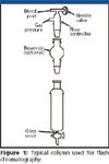
Figure 1
Improvements in column design in flash chromatography began with the widespread use of soft gels such as Sephadex (GE Healthcare, Waukesha, Wisconsin), BioGel (BioRad Laboratories, Hercules, California), and similar packing materials in the 1960s. These gel filtration and chromatographic media were composed of soft macroscopic beads synthetically derived. The columns were of glass and plastic construction. To permit low-pressure pumps of the time to move solvents down the column faster, plastic threaded endfittings were used to provide a tight seal. Plastic inlet and outlet tubes that allowed the columns to be affixed to a low-pressure valve for injection (instead of pipetting) and to direct column effluent to a detection device were provided. To give an even tighter, more stable and reproducible packed bed, endfittings with height-adjustable plungers, as depicted in Figure 2, were developed. The packed bed was compressed in an axial direction. With these early column designs, pressures as high as 80 bar could be achieved. To retain the media, replaceable porous plastic frits were used rather than glass wool. Water-jacketed versions allowed bed temperature control for low-temperature chromatography of heat-sensitive biomolecules or at higher temperature control to improve solute mass transfer.
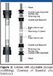
Figure 2
Another major advance was the availability of functionalized silica media, the same types of bonded phases that were available in high performance LC (HPLC). Packing materials with particle sizes in the 30–60 μm (200–400 mesh) range were made available with such familiar groups as C18, amine, cyano, diol, strong anion exchange, and strong cation exchange. Sometimes bonded-phase TLC plates with the same phases as the flash columns were available for assisting in method development.
As the need for flash chromatography expanded, manufacturers of flash columns began to develop more sophisticated instrumentation that resembled low-pressure HPLC systems. Systems became controlled from a central controller (standalone or PC-interfaced) that provided more automation capabilities than had been available earlier. Detectors matched with the flow rate requirements, pumps that provided better flow stability and higher pressure capability than the peristaltic pumps used in early flash chromatography became available making the flash technique a more expensive proposition. Automated fraction collectors that had been available for some time also became more sophisticated and allowed for programming ability to provide flexible collection of peaks based upon threshold and peak signal variation rather than by time.
The flash column design also became more advanced with plastic material construction (for example, polypropylene, polyethylene, and polyvinylidene fluoride), higher pressure ratings, improved frit design, and the disposable cartridge format. Prepacked columns became the norm especially for the bonded phase sorbents. Cartridge columns were made more universal so that they could be interfaced with multiple flash chromatographs. Particle sizes also were reduced to provide better chromatographic efficiency. Particle sizes in the range of 15–40, 25–40, and 40–63 μm were made available from various suppliers such as Merck (Darmstadt, Germany), Biotage (Charlottesville, Virginia), Teledyne ISCO (Lincoln, Nebraska), and Baker/Mallinkrodt (Philipsburg, New Jersey). Recently, spherical flash silica particles with narrower particle size distributions, higher mechanical strength, better efficiency, better packing reproducibility, and fewer fines to give a lower pressure drop than irregular particles became available from Baker/Mallinkrodt (4).
Early Analytical HPLC Columns
The late 1960s was really the advent of modern analytical HPLC. Surprisingly, the first commercial columns did not have the 4.6-mm internal diameter that is today's standard dimension. The first commercial high pressure columns were 1.0-mm i.d. and consisted of a coiled stainless steel column about 3 m long. This pellicular ion exchange column was developed in the 1960s by Csaba Horvath and Sandy Lipsky, both professors at Yale who formed a small packing's company called Northgate Laboratories (Hartford, Connecticut) that developed these columns specifically for the now defunct Picker Nuclear LSC-1000 nucleic acid analyzer. This equipment was used for the measurement of nucleosides and nucleotides in biological fluids. The first silica-based pellicular packings were based upon long straight stainless steel columns of 2.1-mm i.d. by as much as 50 cm in length. Dupont's (Wilmington, Delaware) Zipax and Waters Associates (Milford, Massachusetts) Corasil were the packings provided. In the early 1970s, the first silica-based microparticulate (5–10 μm) columns, which were slurry packed, called MicroPak (Varian Associates, Walnut Creek, California) were also 2.1-mm i.d. columns but because they were more efficient than earlier columns, lengths of 10–15 cm became standard. For those interested in the beginnings of column design in the early days of HPLC, I wrote a review article over a decade ago reviewing the first 25 years (5).
The establishment of 4.6 mm as a standard column internal diameter in the 1970s did not result from a rigorous theoretical study or some magical dream of a column's chemist. This diameter was chosen because that size of stainless steel tube was readily available at a reasonable price, the outer diameter was compatible with the 1/4 inch compression fittings used for packed gas chromatography columns, and that larger internal diameter (relative to the 1.0- and 2.1-mm i.d. columns of the early days) permitted the gradient pumping systems to deliver a fairly reproducible binary mobile phase composition without generating a lot of baseline noise from mixing irregularities. For 4.6-mm i.d. columns operating at flow rates of 1.0–2.0 mL/min, the binary high-pressure pumping systems were able to give good reproducible flow even at 1–2% B mobile phase. A typical compression-fitting column is depicted in Figure 3.
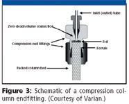
Figure 3
Compression fittings were able to withstand the pressures as high as 5000 psi that became the de facto standard operating pressure for pumps. Columns of 25-cm lengths packed with 10-μm particles, which were popular in the 1970s, gave back pressures well under the upper limits of the pumps. In addition, the wall thickness for a 4.6-mm i.d. by 1/4-in. o.d. column provided a safety factor at that operating pressure, another reason why 4.6 mm became the popular internal diameter. Companies such as Swagelok (Cleveland, Ohio) and Parker-Hannifin (Huntsville, Alabama) answered the call and developed reliable low-dead-volume stainless steel endfittings. Handy & Harmon (New York, New York) and other tubing manufacturers developed relatively smooth-bore stainless steel column tubing to meet the needs of the rapidly growing HPLC columns market. The smoothness of the internal bore of the HPLC column was always an area of concern because wall effects were known to cause detrimental flow characteristics that affected column efficiency (6).
Number 316 stainless steel became the standard metal for columns, fittings, tubing, and so on, although occasionally Number 304 stainless steel and Hastaloy were used. Both were relatively inert to attack by most chemicals, solvents, and buffers commonly used, but hydrochloric acid could corrode the stainless steel surface. Sometimes, these corroded stainless steel systems required passivation by passage of 50% nitric acid in water but most column packings could not stand up to this treatment so this treatment was used only for hardware.
The frits were always an important consideration in the construction of an HPLC column. The main purpose of the frit is to retain the chromatographic media. They must allow unimpeded, homogeneous flow and must withstand high pressures of the column. Most frits were made of sintered, porous stainless steel and were integrated into the endfitting or into the end of the column. The frits are defined by their average pore size such as 0.5, 2.0, or 5.0 μm but they actually have a pore size distribution. Because the overall pore distribution of the frit must be lower than the smallest particle in the HPLC packing's distribution, it is always a tradeoff between the use of a frit of low porosity (which gives higher back pressure and is more prone to plug with particulates) and the particle size distribution of the packing material. Ideally, the frit porosity should be high enough to allow good flow but low enough to retain all the particles. Most columns have permanent frits. Some columns have replaceable frits so that if the frit becomes contaminated it can be removed and replaced. Frits must be removed very carefully because they are in contact with the packed bed and quite often some of this bed is removed in the process, possibly creating a void. These days, most chromatographers dispose of a column rather than spending precious time replacing frits.
Because the inlet frits in column endfittings are porous media, they can act as a filter bed and can retain particulates. If these particulates are allowed to build up, the inlet frit can become clogged and the pressure starts to build up, occasionally even approaching the pump's upper pressure limit. Sometimes reversing the flow on the column can remove these particulates without disturbing the packed bed. Some columns might have a different porosity frit on the top of the column than on the bottom of the column and reversing it can cause a loss of packing. Consult the column instruction manual to see if your column can be reversed.
Currently, the standard dimension for HPLC analytical columns is 250 mm × 4.6 mm and they are packed with 5-μm particles. Although for general HPLC applications shorter columns are in vogue, there are still many validated methods that are performed on the longer columns. Many analytical users are now standardizing on 150 mm × 4.6 mm columns packed with 3.0–3.5 μm particles. The newer shorter columns (less than 50 mm) with 2.1- and 4.6-mm internal diameters packed with sub-2-μm media, although generating a lot of interest in the chromatography community, are still a small fraction of current columns in popular use.
Analytical HPLC Cartridge Columns
Since the beginnings HPLC columns were considered to be a consumable and after columns were exhausted, they were thrown away. Most users regretted throwing away these stainless steel columns so sometimes they would empty the spent packing, clean and repack them, which was always a nuisance. To aid these people, a whole industry of column refillers sprang up, especially in Europe. Because endfittings often represented a major part of a column's cost, analysts wanted to eliminate them or find ways to reuse them and the cartridge column concept was born.
Brownlee Laboratories, which is now part of PerkinElmer (PerkinElmer Life and Analytical Sciences, Wellesley, Massachusetts) designed the first cartridge column. The Brownlee system had a sleeve (cartridge holder) in which the fitting-less column would be contained. The reusable endfittings could be finger-tightened and the columns used just like a regular column. When the columns were "dead," the users merely removed them from the holder and inserted a new one. The endfittings were an integral part of the holder, and, therefore, required no replacement. Figure 4 shows a picture of the Brownlee cartridges and cartridge columns still on the market today, 25 years after their development. The newest cartridge columns have 7000-psi capability.
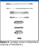
Figure 4
E. Merck (Darmstadt, Germany) designed an alternative type of cartridge that had no sleeve but included reusable endfittings. In this design, called the Manucart, the column had grooves in which two-piece reusable endfittings were retained by a nut placed at the column's end (see Figure 5). The Manucart system could be finger-tightened also. The columns contained most of Merck's popular phases such as LiChrospher and LiChrosorb. This system was very popular in Europe and columns were sold in economical three-packs to save even more money.
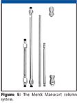
Figure 5
Analytical cartridge columns are now available in many lengths, internal diameters, and styles from many vendors. Cartridge holders for analytical columns as short as 10 mm can now be purchased. The early cartridge columns often were criticized for developing leaks and causing undue band broadening. The latest generation of cartridge columns has overcome many of these early design difficulties and provides reliable, high efficiency separations.
Guard Columns and In-Line Filters
Chromatographers found that column life was sometimes less than they expected. In the early days, they were not always aware of the limitations of the HPLC columns, many of which were silica-based, and of the LC systems that shed small particulates from pump seal and injector valve wear. Some chromatographers did not always filter their samples thereby injecting small amounts of particulates picked up during sample preparation steps. Thus, columns sometimes developed high back pressure with time. Often the back pressure was the result of a plugged inlet frit that could not be unplugged.
Thus, the need for column protection devices came about. An in-line filter is a device that contains a porous frit (sometimes replaceable) that is designed to prevent particulates from building up on the analytical column downstream. It can be placed in one of two places: between the pump and the injection valve or between the injection valve and the column. If it is placed before the injector, then the filter will remove pump seal wear materials and solvent particulates. If it is placed between the injector and the column, it will serve to protect the column against pump and valve wear materials and unfiltered injected samples. Modern designs of in-line filters have very little dead volume so contribute minimally to band spreading or to the gradient delay (dwell) volume. In-line frits can only remove particulates and not chemical contaminants.
Guard columns are short versions of analytical columns usually filled with the same (or a weaker, never a stronger) packing material. Placed between the injector and the analytical column, the guard column can not only function as an in-line filter but also can retain strongly retained sample components, thus, protecting the analytical column. To connect a guard column to an analytical column, the shortest possible piece of low volume connecting tubing should be used. Otherwise, extracolumn band spreading can occur and, thus, a loss of efficiency. Guard columns are considerably less expensive than the analytical column that they protect. Therefore, chromatographers can afford to replace them on an as-needed basis. The use of guard columns has increased over the years as users realize their value in cutting laboratory expense and prolonging column life (7).
The concept of an integrated guard-analytical cartridge column combination came about during the mid-1980s. Designed to avoid almost all dead volume by eliminating connecting tubing, the guard column in these systems is often butted against the analytical column, thus, maintaining the full efficiency of the analytical–guard column combination. Many of these systems could be assembled finger tight. An example of an integrated system is depicted in Figure 6 that shows the Varian (Palo Alto, California) ChromSep column. The Merck Manucart cartridge system has a very clever design. Rather than purchasing extra parts to connect an integrated guard column, one merely has to invert the two ferrules that hold the cartridge in place and the cartridge guard column conveniently fits snugly and in close proximity to the analytical cartridge using all the same fittings.
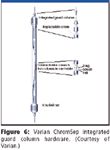
Figure 6
Modern Analytical HPLC Columns
Since the early days of HPLC, analytical column design has changed in three areas:
- column dimensions: very short and very long columns filled with smaller sub-2-μm particles for high throughput separations; narrow and microbore columns; nano- and capillary columns;
- column configurations: chip-based columns; and various preparative column systems; and
- columns based upon new construction materials for greater inertness.
Column dimensions
Table I depicts the nomenclature, dimensions, and approximate operating parameters for modern HPLC columns.

Table I: Typical column dimensions in HPLC
Shorter columns: With the interest in productivity gains and high throughput separations, column lengths have been reduced to less than 50 mm, some as short as 10 mm (8). Internal diameters generally range from 1.0 to 4.6 mm. Because length is proportional to separation time, separations on shorter columns are more rapid. However, shorter columns provide lower efficiency, so to retain efficiency, the particle size is reduced, typically to 3.0–3.5 μm but sometimes to sub-2 μm (9). Such a column gives faster separations, in the range of 1–2 min for simple separations. Although the decrease in particle size causes an increase in back pressure, these shorter column lengths do not cause a greatly increased pressure that might exceed the capability of existing HPLC pumps.
Longer columns: With the interest in handling more difficult separations for samples with large numbers of compounds such as might be encountered in the tryptic digest of a protein or a natural product, longer columns packed with very small particles usually in the sub-2-μm range are becoming more popular. Currently, commercial high-resolution columns are as long as 150 mm with internal diameters of 1.0–4.6 mm. To achieve reasonable separation times, flow velocities are such that column back pressure can exceed those of regular 400-bar HPLC pumps. Therefore, newer pumps with pressure capabilities of 600–1000 bar have become available. Researchers have been experimenting with columns packed with particles as small as 1–1.5 μm in diameter with column lengths even longer, as much as 50 cm (10), in the ultrahigh pressure LC technique. These columns can generate back pressures in the several thousand bar range and will require a new generation of high-pressure systems and column materials that are stable at these extremely high pressures.
Solvent saver columns: When the diameter of a column is reduced, in order to maintain the same linear velocity (and therefore the separation time), the flow rate is reduced by the inverse radius ratio squared. Thus, decreasing the column diameter from 4.6-mm to 3.0-mm and keeping the same length, the flow rate should be reduced by a factor of (1.5/2.3)2 or 0.43. Such a change will reduce solvent usage by almost 60%. Most liquid chromatographs can be used with 3.0-mm i.d. columns without affecting resolution.
Narrow- and microbore columns: When the available mass of sample decreases and high sensitivity is required, a reduction in the internal diameter of the HPLC column is warranted. As the column diameter decreases and the same sample mass is injected (provided the column is not overloaded), the sensitivity increases as the inverse column diameter squared. The relative increase for various column diameters can be seen in the last column of Table I.
Compared with the 3.0-mm columns cited above, for further reduction in flow rate and solvent usage as well as increased sensitivity in sample-mass limited situations, these columns find their place in the laboratory. The 2.1-mm i.d. columns are quite popular with those using LC–mass spectrometry (MS) since the typical flow rates are in the 0.2–0.5 mL/min range that is compatible with electrospray ionization techniques. However, for optimum use of these columns, older HPLC instruments, especially those that were developed primarily for use with 4.6-mm i.d. columns, may need system dead volume modifications to cut down on extra column effects. In addition, especially for the 1.0-mm i.d. microbore columns, the instrument may need to be tested to make sure that it can reproducibly deliver the lower flow rates and gradient accuracy and precision.
Capillary and nano-nolumns: These columns (an example is pictured in Figure 7) are most often used for the investigation of trace levels of proteins and peptides such as encountered in the proteomics segment. These columns require very low flow rates and thus are very compatible with MS, a detection technique that lends itself to the measurement and identification of tryptically digested peptides. For such columns, low dispersion HPLC hardware is required as well as pumps and gradient systems capable of delivering precise flow rates below 50 μL/min down to a few hundred nanoliters per minute. Most conventional HPLC instruments are not fully compatible with these smaller internal diameter columns. Split-flow systems are sometimes used but the user is cautioned to make sure that the data is reproducible. For nano-columns, fused silica tubing is most often used for construction; for capillary columns, either stainless steel, lined stainless steel, or fused-silica tubing has been used.
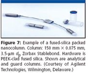
Figure 7
Chip LC
There is currently a great deal of interest in the total miniaturization of the HPLC experiment including the column configuration. Columns can be constructed with very small dimensions on glass or plastic chips. The narrow channels can be etched or laser-ablated with dimensions in the 50-μm diameter range by lengths as long as tens of centimeters if the serpentine format is used. Column configurations are not always cylindrical as in regular HPLC nevertheless columns perform adequately. Chromatographic beds can be packed during fabrication or can be formed in situ using monolithic technology. Current work involves constructing integrated pumping and detection systems to make the working chromatograph a truly miniaturized separation and measurement device.
Columns Constructed from New Materials
The traditional HPLC columns have been constructed from stainless steel tubing and occasionally titanium or other metal with different surface properties. In an attempt to have more inert surfaces especially in dealing with biological molecules and trace metal analysis, new materials have been created. Some biological molecules interact directly with stainless steel and can thereby be denatured or adsorbed. For the analysis of inorganic ions, depending upon the mobile phase conditions, trace metals can sometimes be leached from the interior surface of the stainless steel columns causing erroneous results.
To cut down on surface interactions, glass-lined or PTFE (Teflon)-lined stainless steel have been used for better inertness.
One of the remarkable discoveries in the polymer world that was adapted for HPLC connections, fittings, ferrules and, eventually columns was PEEK (polyetheretherketone). PEEK is an amazingly strong, heat-resistant plastic that can be fabricated into many different forms. It is chemically resistant to a wide variety of compounds and has been found to be an excellent replacement to stainless steel. Many column manufacturers supply biochromatography columns with PEEK construction. PEEK-clad fused silica tubing also has been used to make capillary LC columns. These products are sold by SGE International (Austin, Texas) as PEEKsil and by Valco Instruments (Houston, Texas) as PEEKclad-FST.
Other Column Configurations
In preparative columns where high flow rates and more loosely packed beds cause settling over time, resulting in voids at the column head, axial compression (similar to that shown in Figure 2) has been used. In axial compression, a dynamic or static compression device applies some form of longitudinal pressure to the packed bed (usually continuous) so that the particles are maintained in a void-free, uniform arrangement. Earlier, I reviewed this form of bed compression and direct the reader to reference 11 for further information.
Radial compression has been used to cut down on the so-called wall effects. For a radial-compression column, the walls are flexible, which is achieved by packing the bed into a tubular polymer cartridge (terminated by an appropriate stainless steel frit). The cartridge is contained inside a supporting stainless steel cylindrical column. The column is filled with a very dense slurry of the packing material and another frit fitted to the top of the bed. The bed is then compressed radially by applying pressure to the outside walls of the polymer cartridge. The applied pressure can be either pneumatic or hydraulic. Radial-compression columns were popular a couple of decades ago.
An interesting combination of radial and axial compression for flash chromatography columns is provided by Gyan (Genoa, Italy) (Figure 8). Their JumboFlash system uses a unique design. Two stainless steel shells are placed around the plastic packed cartridge. When you turn the handle, a compression fitting moves down to generate axial compression. At the same time, the shells are tightened to provide radial compression. The combination of the two provides true 360° compression and apparently eliminates any swelling.
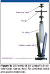
Figure 8
A novel column packing device and hardware system for preparative chromatography called the Axia was introduced by Phenomenex (Torrence, California). Figure 9 briefly shows the operation. The packing media slurry is placed into the column blank and the bed is axially compressed by a hydraulic piston to a predetermined density (Figure 9a) determined by computer-control. The packing piston is integrated into the column such that the packing pressure is never released. The media is never allowed to relax and therefore remains in a compressed state. The unit is held intact with radial sleeves (Figure 9b). The top portion of the column holder is affixed and ensures a tight fit of hardware components (Figure 9c). The final column (Figure 9d) can be connected to the preparative chromatograph using standard compression fittings.

Figure 9
Future Column Hardware Developments
There is no doubt that new column configurations will be developed continually. The new challenge will be to provide columns and column packings that will be stable and reproducible in the ultrahigh-pressure LC world. Perhaps new polymeric materials will come along that will withstand these high pressures as well as provide increased inertness. With high temperature now becoming an important parameter in method development, high temperature columns that will be leak-free at high pressure will be important. As miniaturization continues to evolve, column formats will probably change as researchers find new ways to incorporate sorbent material into the tiny channels encountered in chip-based systems. Conventional slurry packing techniques with discreet particles can still be used, but in situ created monoliths might win out due to their relative ease of preparation. Recent reports of open-tubular and porous-layer open tubular columns (12,13) might provide the ultimate efficiency but commercialization of such columns and HPLC systems to operate them might be off in the distant future.
Ronald E. Majors "Column Watch" Editor Ronald E. Majors is business development manager, Consumables and Accessories Business Unit, Agilent Technologies, Wilmington, Delaware, and is a member of LCGC's editorial advisory board. Direct correspondence about this column to "Sample Prep Perspectives," LCGC, Woodbridge Corporate Plaza, 485 Route 1 South, Building F, First Floor, Iselin, NJ 08830, e-mail lcgcedit@lcgc-mag.com
References
(1) M. Tswett, Ber. Dtsch. Bot. Ges. 24, 316–326 (1906).
(2) M. Tswett, Ber. Dtsch.Bot.Ges. 24, 384–393 (1906).
(3) W.C. Still, M. Kahn, and A. Mitra, J. Org. Chem. 43, 2923 (1978).
(4) R.E. Majors, LCGC 24(3), 248–266 (2006).
(5) R.E. Majors, LCGC 12(7), 508–518 (1994).
(6) K.E. Collins, A.C. Franchon, I.Cristina, S.F. Jardim, E. Radovanovic, and M.do Carino Goncalves, LCGC 18(2), 106–117 (2000).
(7) R.E. Majors, LCGC 15(11), 1008–1015 (1997).
(8) R.E. Majors, LCGC 23(7), 1248–1255 (2005).
(9) R.E. Majors, LCGC 23(12), 1248–1255 (2005).
(10) J.W. Thompson, J.S. Mellors, J.W. Eschelbach, and J.W. Jorgensen, LCGC 24(S4), 16–20 (2006).
(11) R.E. Majors, LCGC 22(7), 606–617 (2004).
(12) B. Karger, HPLC 2006, San Francisco, California, June, 2006.
(13) F. Svec, HPLC 2006, San Francisco, California, June 2006.

.png&w=3840&q=75)

.png&w=3840&q=75)


.png&w=3840&q=75)


.png&w=3840&q=75)


