Using Computerized Pneumatics - Part 2
LCGC Europe
Computerized pneumatic control adds a very capable multipurpose tool to the chromatographer's tool belt.
Computerized pneumatics facilitate set-up and operation of both capillary and packed columns and offer chromatographers improved performance over manually operated pneumatics in terms of retention time stability and split or splitless quantification. The first part of this series introduced the basics of computerized pneumatics,1 showed how a gas chromatography (GC) system controls flow or pressure and discussed the fundamentals of operation as well as some pitfalls that can arise when changing the pneumatic configuration.
The capabilities of computerized pneumatic control extend beyond the basic capillary-column modes of total flow control for inlet splitters and pressure-drop control for columns. As discussed in the first part of this series, given the correct column dimensions and carrier gas type, computerized pneumatic systems will calculate capillary column flows and velocities that correspond to specified pressure drops and oven temperatures, and then report the resulting flow and velocity to the operator. Going further, given a specific flow-rate or average carrier gas linear velocity, the pneumatic system can also calculate and set the pressure drop required to produce the desired flow or velocity.
This is particularly convenient for columns attached to split–splitless inlet systems, which control the column pressure drop directly but not the column flow-rate itself. The pressure drop that is required for a particular flow depends upon the oven temperature as well as the column dimensions and carrier gas, so the operator must specify the temperature at which the desired flow is to be achieved: this is nearly always the same as the initial or operating oven temperature. When the GC system receives a flow or velocity setpoint, the corresponding pressure is set automatically by the pneumatic system.
So far so good, but what happens when the column temperature increases during oven temperature programming? The column flow-rate depends upon the oven temperature, as well as many other factors, and so chromatographers expect the flow to change during temperature programming. The physics of flow through an open tube are well understood, though, and computerized pneumatic systems incorporate a mathematical model that accurately predicts the interrelationships of pressure, flow and linear velocity.
Pressure Programming
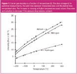
The dependency of capillary column flow and velocity on the column pressure drop is determined by the column dimensions and the carrier-gas viscosity. As temperatures increase, so does the viscosity, which causes the flow and velocity to decrease at higher temperatures. Figure 1 shows the measured relationships of temperature and gas viscosity for three common GC carrier gases. Computerized pneumatic systems use the functions of temperature represented by the lines plotted in Figure 1, which are fitted to the measured viscosity data, to calculate viscosity dynamically as the oven temperature changes. At an inlet pressure below 30 psig, the column flow-rate and outlet velocity are roughly proportional to the viscosity, to within about 10%. Figure 1 gives a good idea of how large the viscosity effect can be when a temperature program spans a large temperature range. Going from 50 °C to 250 °C, for example, causes helium viscosity to increase by around 40%. The other carrier gases undergo viscosity changes of a similar magnitude.

Figure 1
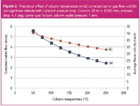
Until computerized pneumatics was widely available, nearly all split–splitless inlets operated at a constant inlet pressure drop. This meant that the column flow would decrease as the temperature went up during temperature programming, because the viscosity was increasing as well. Figure 2 illustrates the effect on corrected theoretical carrier gas flow and average linear velocity of changing the oven temperature while holding the pressure drop constant, for a 30 m × 0.530 mm wide-bore column with 4.1 psig of helium carrier gas and with the column outlet at 1 atm. The column outlet flow-rate at a column temperature of 50 °C is 6.5 mL/min, and it decreases to 4.3 mL/min at 250 °C, resulting in a 34% loss. Figure 2 gives flow-rates corrected from the column temperature to a standard temperature (usually 25 °C), which amounts to a larger 57% drop in flow as would be measured with a flow meter or as is displayed on the gas chromatograph. Across the same temperature range, the average linear velocity decreases from 40 cm/s at 50 °C to 28 cm/s at 250 °C, a 30% loss.

Figure 2
Constant Column Flow
A constant column outlet flow is desirable for consistent detector functioning during temperature programming. Mass-spectrometric detector solute ionization fragmentation patterns depend upon the source pressure somewhat, which in turn depends upon the incoming flow-rate. For capillary columns that are interfaced directly to a mass spectrometer, it is better to maintain a constant column outlet flow: the alternative of using an outlet splitter and restrictor can give unacceptable sensitivity losses. When a flame ionization detector is used with hydrogen carrier gas, it is a good idea to keep the total hydrogen flow through the flame ionization detector constant. This can be accomplished in two different ways with computerized pneumatics: either by maintaining a constant column outlet flow-rate or by programming the detector hydrogen flow upward enough to compensate for the decrease in the column outlet flow-rate, that is, by keeping the sum of the column and detector hydrogen flows constant.
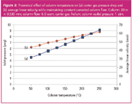
A computerized pneumatic system can increase the column pressure drop sufficiently to maintain a constant corrected carrier-gas flow-rate as the temperature increases. Figure 3 shows how this choice affects the pressure drop and the average linear velocity for the same wide-bore column. A constant corrected column outlet flow of 6.0 sccm is maintained by increasing the pressure drop from 4.5 psig at 50 °C to 9.1 psig at 250 °C. Note that the average linear velocity increases as the oven temperature goes up, which perhaps runs counter to intuition. It is also possible for the pneumatic system to calculate and set the pressure drop required to keep the average linear velocity constant as the temperature changes, but this means the flow will decrease over the temperature program range.

Figure 3
Ultimately, the most important consideration might be peak resolution and not necessarily detector performance, especially in situations in which the separation is marginal. Deciding whether constant pressure or constant flow will yield a better temperature-programmed separation, let alone the effects of changing the temperature program itself, is a more complex consideration that does not give itself over very well to purely theoretical modelling. In the first place, relative peak positions in a chromatogram depend heavily upon the thermodynamic relationships between the stationary phase and a solute's chemical characteristics such as vapour pressure and polarity. Individual peaks move in different ways relative to each other as the temperature changes, although a homologous series such as the normal hydrocarbons tend to move all together. In general, the more the chemical natures of a pair of peaks differ, the greater the effect of changing the column temperature or temperature program will be.
Next, consider the effects that pressure programming might have on the thermal conditions that solutes experience as they move through the column. At higher flows, peaks will be eluted earlier in a temperature program and, therefore, at somewhat lower column temperatures. But this change of elution temperature might or might not improve the separation of a pair of peaks. This effect is illustrated in the series of test chromatograms that are shown in Figure 4. Here, a test mixture was injected with either constant pressure or constant flow programmed pneumatics, with the initial pressure drop the same in either instance, with the program rate doubling in each of four consecutive runs.

Figure 4
Flow Control Versus Pressure Control
The effects of constant flow compared to constant pressure operation are clear in these chromatograms: the peaks all are eluted sooner with constant flow. For example, the last peak in the run, 2,4-dimethylphenol (DMP), is eluted at 24.85 min with constant pressure and at 22.79 min with constant flow at the 6 °C/min oven temperature programming rate. This makes sense because the inlet pressure is increasing continuously as the oven temperature rises. Similar reductions in retention times hold for the other peaks when the flow-rate is kept constant.
The effects on retention times of increasing the temperature program rate far outweigh the differences observed between constant pressure and constant flow pneumatic modes. The DMP peak moves in from 40.66 min at 3 °C/min (elution temperature = 166 °C) to 11.1 min at 24 °C/min (elution temperature = 250 °C). Again, there are no surprises here: the temperature effects are quite strong.
The overall effect on peak resolution, however, is somewhat unexpected. The two closest peak pairs in terms of elution, n-decane/2-octanone and 2,6-dimethlyaniline (DMA)/DMP, show opposite trends. Resolution increases with increasing temperature program rate for the first pair but decreases for the second pair, regardless of the pneumatic programming mode. What is interesting is that constant pressure mode gives slightly better resolution than the constant flow mode for the former pair but makes little difference for the latter peak pair. Figure 5 plots the resolution of these two peak pairs as a function of the temperature programming rate and the pneumatic mode.

Figure 5
Although the resolution of DMA/DMP is high in all instances — there is no reason to be concerned with this peak pair itself — if there were other peaks between these two in a "real" sample, then it would be of interest to find an optimum set of conditions for the overall chromatogram instead of choosing the best case for the first peak pair along with the shortest total time at 24 °C/min. A temperature programming rate of 12 °C/min might be a good choice because it keeps the resolution of the first pair while still using a good portion of the available resolving power between the second pair.
A better choice might be to use a two-ramp temperature program instead of a compromise single-ramp program. At the time that the first peak pair is being eluted, the later-eluted DMA/DMP pair has not started to move along the column much, so cutting the temperature programming rate back to 6 or even 3 °C/min halfway through the run would make some sense. That way, the later-eluted pair would behave in much the same way it would if the entire chromatogram were run at the lower rate, while the earlier pair would get the full advantage of the maximum available resolution. Of course, other solutions might include changing to a narrow-bore column or investigating the effects of a different stationary phase composition.
Finally, I have to mention that other more advanced (and complex) column configurations for multidimensional GC, including column change-out devices, backflushing systems and comprehensive GC×GC, are facilitated greatly by computerized pneumatic systems in combination with various passive pneumatic switching devices that have been available for a long time and continue to be improved.
Conclusion
Computerized pneumatic control adds a very capable multipurpose tool to the chromatographer's tool belt. Such systems make setting up a GC system easier by automating some tasks. They can give more repeatable results from run-to-run and laboratory-to-laboratory through performance gains inherent in their electromechanical control systems. Some detector performance improvements can be obtained with constant carrier-gas flow control. And computerized pneumatics excel in facilitating advanced separations techniques. But when it comes to chromatographic performance gains in solute resolution, at least for a temperature-programmed polar wide-bore column, there is little difference between the constant flow or constant pressure control of the column carrier gas.
"GC Connections" editor John V. Hinshaw is senior staff engineer at Serveron Corp., Hillsboro, Oregon, USA and a member of the Editorial Advisory Board of LC•GC Europe.
Direct correspondence about this column to "GC Connections", LC•GC Europe, Advanstar House, Park West, Sealand Road, Chester CH1 4RN, UK, e-mail: amatheson@advanstar.com
For an ongoing discussion of GC issues with John Hinshaw and other chromatographers, visit the Chromatography Forum discussion group at www.chromforum.com
References
1. J.V. Hinshaw, LC•GC Eur., 21(1), 24–28 (2008).
2. J.V. Hinshaw and L.S. Ettre, Introduction to Open-Tubular Column Gas Chromatography, (Advanstar, Cleveland, 1994), p. 25.

University of Rouen-Normandy Scientists Explore Eco-Friendly Sampling Approach for GC-HRMS
April 17th 2025Root exudates—substances secreted by living plant roots—are challenging to sample, as they are typically extracted using artificial devices and can vary widely in both quantity and composition across plant species.
Sorbonne Researchers Develop Miniaturized GC Detector for VOC Analysis
April 16th 2025A team of scientists from the Paris university developed and optimized MAVERIC, a miniaturized and autonomous gas chromatography (GC) system coupled to a nano-gravimetric detector (NGD) based on a NEMS (nano-electromechanical-system) resonator.
Miniaturized GC–MS Method for BVOC Analysis of Spanish Trees
April 16th 2025University of Valladolid scientists used a miniaturized method for analyzing biogenic volatile organic compounds (BVOCs) emitted by tree species, using headspace solid-phase microextraction coupled with gas chromatography and quadrupole time-of-flight mass spectrometry (HS-SPME-GC–QTOF-MS) has been developed.


