Tips & Tricks GPC/SEC: System Peaks or Ghost Peaks in GPC/SEC
The Column
Extraneous peaks, unrelated to the solute to be characterized, are quite common in gel permeation chromatography/size-exclusion chromatography (GPC/SEC), especially when refractive index (RI) detection is used. This instalment of Tips & Tricks explains why system or ghost peaks appear and how to minimize their appearance.
Sergii/stock.adobe.com

Extraneous peaks, unrelated to the solute to be characterized, are quite common in gel permeation chromatography/size-exclusion chromatography (GPC/SEC), especially when refractive index (RI) detection is used. This instalment of Tips & Tricks explains why system or ghost peaks appear and how to minimize their appearance.
System peaks are a common phenomenon in liquid chromatography (LC). When an injection is performed, the number of peaks in the chromatogram is usually larger than the number of analytes present in the sample. The omnipresent, not sample-related, additional peaks are the so-called system peaks and are even observed when injecting pure mobile phase.
In the literature, system peaks are sometimes also called ghost peaks, eigenpeaks, pseudo peaks, vacancy peaks, or similar. Although ghost peaks seems to be an appropriate name, the phrase system peaks is favourable as the peaks are actually related to the system and the chromatographic conditions applied (1).
Identification of System Peaks
In gel permeation chromatography/sizeâexclusion chromatography (GPC/SEC), system peaks usually appear at the end of the chromatographic run indicating the transition from entropy-dominated size-based separation to enthalpy-dominated interaction chromatography. It is important to identify system peaks so that they can be excluded from data analysis. The number and intensity of the system peaks will increase with decreasing mobile phase quality. If the mobile phase is stored too long in the reservoir or if it is used in constant recycling mode, more and larger system peaks will appear.
It is good practice in GPC/SEC to inject at least one blank sample in every sequence to help identify the system peaks. Blanks consist of mobile phase that has been treated in the exact same way as the samples. Therefore if the samples are filtered into the vials, the blank should also be filtered into the vial.
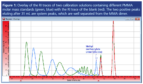
Figure 1 shows an example of GPC/SEC separation of polymethyl methacrylate (PMMA) standards of different molar mass in tetrahydrofuran (THF). Here the differential refractive index (RI) traces of two different standard mixtures (blue and green trace) are overlaid with the RI trace of the blank injection (red).
This procedure allows straightforward identification of the two positive peaks eluting after 31 mL elution volume as system peaks. As they are not sample related, they have to be excluded from result determination of the samples. This was done by setting the appropriate integration limits (compare red triangles).
Please note that national and international standards often require a two-step data evaluation procedure for GPC/SEC with independent settings for baseline limits and integration limits (2). While the right baseline limit should include the system peaks (to ensure the signal properly returning to the baseline), the integration limits are required to exclude any system peaks. The number average molar mass (Mn) and the polydispersity index (PDI) will be particularly strongly influenced by these settings (3).

Please note that the above analysis also reveals two negative system peaks not shown in Figure 1. Negative peaks are quite common, especially when applying RI detection (4). The identification process is the same, irrespective of the peaks being positive, negative, or a mixture of both.
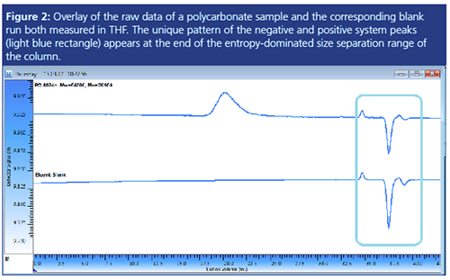
Figure 2 shows the chromatogram of a separation of a polycarbonate in THF overlaid with the chromatogram of the blank. The unique system peak pattern of this setup comprises two small positive peaks and a larger and a smaller negative peak.

Origin of System Peaks
The origin of system peaks is sometimes hard to understand. However, it has to be kept in mind that even in isocratic GPC/SEC the mobile phases are multicomponent because they may contain contaminants or could be spiked with additives such as antioxidants. Dissolved air or additives, buffers, or salts, added to allow for interaction-free separation, enhance the complexity of the overall system.
Generally, system peaks are explained by a loss of equilibrium. When a mobile phase is passing through a chromatography column, an equilibrium between mobile phase and stationary phase is reached. Anything that will influence the mobile phase composition, and thus disturb the equilibrium, will result in system peaks. The injection of a sample solution certainly qualifies as a disturbance of the equilibrium conditions.
The newly introduced sample components will move through the column with velocities different to the equilibrium velocity. Relaxation to new equilibrium conditions will occur and system peaks will appear. Re-equilibration also includes the process of preferential solvation of sample components with one or more mobile phase components. Thus the areas of system peaks can be a strong function of the analytes themselves (1). This is one reason why the use of system peaks as internal flow markers requires a very sound method validation and is generally not recommended (5).
It is good practice in GPC/SEC to prepare the injection solutions with mobile phase freshly taken from the mobile phase reservoir. This ensures that solvent and mobile phase have comparable compositions of mobile phase components. Thus the redistribution of mobile phase components on the stationary phase is less pronounced, resulting in lower peak areas for system peaks.
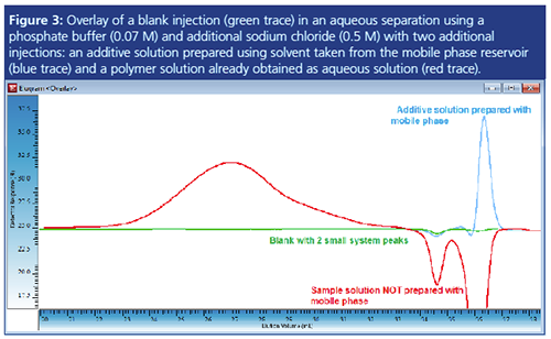
Figure 3 shows an example of an aqueous separation. The mobile phase is a phosphate buffer with sodium chloride added (0.07 M Na2HPO4, 0.5 M NaCl). When injecting the blank, two small negative peaks were detected by the RI detector (green trace). Samples to be characterized were a polymer and an additive. While the additive sample was prepared using solvent taken from the mobile phase reservoir, the polymer sample was already dissolved in water. Therefore the blue RI trace of the additive solution shows comparable signal areas for the system peaks. However, the injection of the polymer solution generates huge negative system peaks because of the lack of the correct concentration of mobile phase components in the sample solvent (salt/buffer). Preferential solvation and reâdistribution of the mobile phase components at the stationary phase are responsible for this. While molar mass determination for the polymer peak is possible, determination of the amount of additive is prevented by the coelution of the additive with the negative system peak. Thus further method optimization is required. Reduction of the injection volume and optimization of sample preparation are the first steps to be considered for method optimization.
Detailed Investigation of System Peaks
In the vast majority of applications, system peaks do not have a negative impact. Once the system peaks are identified, the analysis goals can still be reached, as long as the system peaks do not coelute with the sample components of interest. System peaks are sometimes even used to obtain valuable information including, for example, the void volume of columns (6). Newly appearing or missing system peaks are a hint for a change in the chromatographic system that might be worth investigating.
To minimize system peaks or to get a better understanding of the chromatographic system it can be a good idea to identify which peak originates from the different mobile phase components. A practical approach to this is to prepare the mobile phase components as separate samples and to analyze these in the GPC/SEC system. Thus, injections are done where the mobile phase is spiked with the single components.

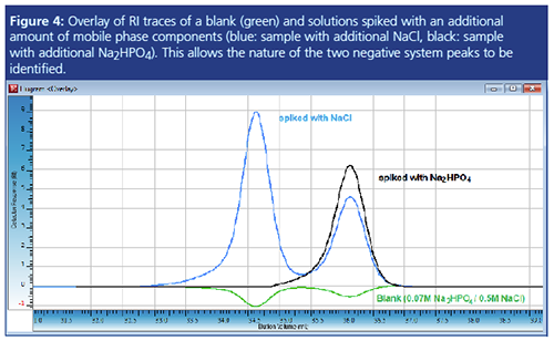
Figure 4 shows an overlay of the RI traces of the blank injection also shown in Figure 3 (green) with the RI traces of an injection with Na2HPO4 added (black) and an injection with NaCl added (blue). While the black curve immediately shows that the second negative peak can be assigned to the phosphate component, the blue trace alone would not allow identification of the NaCl peak. Most probably, as the concentration of sodium chloride is already quite high, the addition of more salt also influences the equilibrium distribution of the phosphate component. The results in Figure 4 were confirmed using different injection volumes and a UV detector as an additional detector.

Summary
- Positive and negative system peaks are a common phenomenon in LC. In GPC/SEC they appear at the end of the chromatographic run.
- System peaks are explained by a loss of equilibrium and relaxation to a new equilibrium.
- The area of system peaks can be a strong function of the analytes; thus system peaks should not be used as internal flow markers.
- Sample preparation with solvent taken from the mobile phase reservoir allows system peaks to be minimized.
- A low injection volume allows system peaks to be minimized.
References
- S. Levin and E. Grushka, Anal. Chem.58, 1602 (1986).
- D. Held, The Column9(2), 2–5 (2013).
- P. Kilz and D. Held, in Quantification in LC and GC - A Practical Guide to Good Chromatographic Data, S. Kromidas and H.-J. Kuss, Eds. (WileyâVCH, Weinheim, 2008).
- D. Held, The Column13(17), 24–27 (2017).
- D. Held and W. Radke, The Column12(6), 24–27 (2016).
- J. Srbek, P. Coufal, Z. Bosáková, and E. Tesarová, J. Sep. Sci.28, 1263 (2005).
Daniela Held studied polymer chemistry in Mainz, Germany, and works in the PSS software and instrument department. She is also responsible for education and customer training.
Friedhelm Gores studied polymer chemistry in Mainz, Germany, and works in the PSS contract analysis department.
E-mail:DHeld@pss-polymer.com
Website:www.pss-polymer.com

New Method Explored for the Detection of CECs in Crops Irrigated with Contaminated Water
April 30th 2025This new study presents a validated QuEChERS–LC-MS/MS method for detecting eight persistent, mobile, and toxic substances in escarole, tomatoes, and tomato leaves irrigated with contaminated water.

.png&w=3840&q=75)

.png&w=3840&q=75)


.png&w=3840&q=75)


.png&w=3840&q=75)


