Seven Common Faux Pas in Modern HPLC
LCGC North America
Because of improved technologies and other changes in modern HPLC, these seven common practices are now highly questionable.
The seven faux pas discussed here are common practices in high performance liquid chromatography (HPLC) that may no longer make sense because of improved technologies or other changes in modern HPLC. Therefore, careful consideration should be given to alternative approaches.
The expression faux pas is French in origin and literally means "false step," or "misstep." Although in English the phrase typically refers to an embarrassing social blunder rather than to a technical error, I am borrowing this expression, and stretching its meaning a bit, as a way to highlight some common practices in high performance liquid chromatography (HPLC) — legacy practices that have been in use for many years — that may no longer make sense because of improved technologies or other reasons in modern HPLC. In this installment, I highlight seven such questionable practices and show why they should not be followed without first considering some alternative approaches:
- Using columns packed with 5-µm particles
- Using 4.6-mm i.d. columns at 1 mL/min
- Filtering HPLC mobile phases
- Using buffered mobile phases
- Preparing fresh reference standard solutions with every assay
- Shaking HPLC sample vials
- Using stainless steel ferrules for column connections
As each topic is discussed, I will offer rationales and references to support why the practice is being called into question — and in many cases, I will offer exceptions to the rule.
Using HPLC Columns Packed with 5-µm Particles
For many years, the "standard" HPLC analytical column has been a 250 mm × 4.6 mm column packed with 5-µm particles that could deliver ~20,000 plates (1,2). In a survey on column trends published in 2012, Ron Majors reported that the "standard" workhorse column was likely to be shifting toward a 150 mm × 4.6 mm column packed with 3-µm particles, which offers comparable efficiencies with a 40% or more reduction in analysis time (3). This trend is not surprising for experienced practitioners because plate count (N) is proportional to the ratio of column length (L) to particle size (dp), expressed mathematically as N ∝ L/dp. The 3-µm particle has proven to be as reliable as its 5-µm counterpart and offers higher performance (lower plate height [H]) while maintaining compatibility with conventional HPLC equipment (1,2). As ultrahigh-pressure liquid chromatography (UHPLC) and liquid chromatography–mass spectrometry (LC–MS) systems are becoming standard equipment in many laboratories, the "standard" column particle sizes are expected to trend downward to sub-3-µm or sub-2-µm particles (4). Another emerging trend is the increased acceptance of superficially porous packings, which have improved particle morphology and substantially higher performance (~20–30%) compared with totally porous materials (5).
Exceptions
Although columns packed with 3-µm particles are generally superior to those packed with 5-µm materials, they do use finer inlet frits (0.5 µm versus 2 µm), which are more prone to clogging from "dirtier" samples. Another exception to this rule may come from specialized columns (for example, size-exclusion chromatography columns for protein analysis) where higher pressure and higher temperature from frictional heating may lead to increased on-column protein aggregation (6).
Using 4.6-mm i.d. Columns at 1 mL/min
The "standard" internal diameter for analytical HPLC columns has been 4.6 mm since the early 1970s and remains that way today (2,3). The reason for the popularity of this diameter might be the wide availability of stock 316 seamless, stainless steel ¼-in. o.d. tubing (which has a wall thickness of 0.035-in., yielding an internal diameter of 4.6 mm). With column hardware of this size, analysts typically used a 1.0-mL/min flow rate (F) as a default (a nice round number which is also the optimum flow rate for columns packed with 5-µm particles).
Figure 1 shows the van Deemter curves of three columns (50 mm × 2.1 mm) packed with 5.0-, 3.5-, and 1.7-mm C18 particles (7). Note that the minimum plate height (Hmin), which defines the efficiency (N) of the column (N = column length/H), is proportional to particle diameter (dp), while the optimum velocity (uopt), the linear velocity associated with Hmin, is inversely proportional to dp (1,2,5).
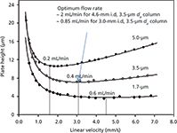
Figure 1: Van Deemter curves for 5-, 3.5-, and 1.7-µm C18 particles. Column: 50 mm à 2.1 mm; mobile phase: 50:50 (v/v) acetonitrileâwater; detection: UV absorbance at 210 nm; temperature: 45 °C; analyte: benzylphenone. Adapted with permission from reference 7.
If we accept the new "default" particle size to be 3 µm (or 3.5 µm) as indicated above, then uopt would be ~3.0 mm/s or 0.4 mL/min for 2.1-mm i.d. columns (equivalent to ~2.0 mL/min for 4.6-mm i.d. columns). A 2.0-mL/min flow rate is less "green," and a 1-L reservoir of mobile phase would last for only ~8 h. However, if one selects a 3.0-mm i.d. column, then the optimum flow rate would be ~0.8 mL/min using geometrical scaling calculations (8,9) as shown below.

The use of 3.0-mm columns reduces solvent consumption while conserving sample (smaller sample volume or concentration) and is also highly compatible with conventional HPLC systems typically used in a quality control (QC) setting. Column efficiency and the effect of extracolumn band broadening are usually not adversely impacted if a modern HPLC instrument with intermediate dispersion is used (variances < 20 µL2) (1,2,5). Many laboratories (including my own) have switched from 4.6 mm to 3.0 mm i.d. as a "preferred" column internal diameter for these reasons (10). The use of 2.1-mm i.d. columns is logically the next step, but requires low-dispersion UHPLC equipment.
The use of smaller internal diameter columns can be advantageous to generate higher resolution under gradient conditions. A useful equation in this regard (1,2,11) is shown below.

Where k* is the average k or retention factor under gradient conditions; tG is gradient time, F is flow rate, and Vm is the column void volume.
A larger k* value typically means higher resolution by allowing greater volumes of lower strength mobile phase to be pumped through the column (1,2). Equation 2 shows that k* is proportional to tG and F/Vm, thus a higher F using the same column and tG will yield higher k* or resolution. So, the use of 3-mm columns is preferable in this regard versus 4.6-mm i.d. columns. Along the same lines, one useful application of this equation is the use of small columns (for example, 50 mm × 2.1 mm), short ballistic broad gradients (tG = 1 or 2 min) at high flow rates of 1.0–1.5 mL/min for quick, in-process testing or high-throughput screening analyses (7,12).
Filtering HPLC Mobile Phases
It is a common practice to filter mobile phases through 0.5-µm membrane filters (nylon, polytetrafluoroethylene [PTFE], or cellulose acetate), using vacuum to draw the solvent across the membrane to remove any particulate matter that may cause problems in the HPLC system or column (1,2). However, this may be redundant since all HPLC-grade solvents and water from purification systems have already been sufficiently prefiltered. An extra filtration step can actually be counterproductive by increasing the chances for chemical contamination, which can lead to more "ghost" peaks in the blank and sample chromatograms (2). By using high-purity reagents (such as ammonium formate at 99.995% purity), many laboratories have been operating well for years without a single vacuum filtration apparatus. Instead, they rely mainly on an annual preventive maintenance program in which the internal filters in the HPLC equipment (in the purge valve and pump compartment) and the 10-µm solvent inlet filters in the mobile phase reservoirs are replaced.
Exceptions
Some situations where mobile-phase filtering is still highly recommended (1,2) are when ion-pairing reagents, low purity buffers (for example, citrates and phosphate), or high salt content mobile phases (6 M sodium chloride) are used, particularly for UHPLC applications using columns packed with sub-3-µm particles (which are more prone to clogging problems). Another situation where extra filtration is warranted is when the quality of the water from purification systems is insufficient because of the quality of the source water or other reasons.
Using Buffered Mobile Phases
For the analysis of acidic and basic analytes (that is, most pharmaceuticals), it is imperative to acidify or basify the mobile phase to control the ionization state of the analytes to maintain good peak shape (2). Simple mobile phases such as 0.1% (v/v) acid in water (for example, trifluoroacetic acid, formic acid, acetic acid, and phosphoric acid) may be sufficient in most cases and can be prepared quickly by pipetting 1 mL of the acid into 1 L of water. Similarly, 0.1% (v/v) ammonia in water works well for many high-pH-compatible columns. Additional filtration of these simple mobile phases is not generally needed as per the previous section. So, buffers have little utility if one uses a low silanophilic activity column with either low- or high-pH mobile phases, and for the injections of low sample mass prepared in mobile phase A as a diluent.
Exceptions
Buffered mobile phases may still be needed for critical purity analyses of complex molecules (for example, compounds with multiple ionizable nitrogen atoms and pKa) and very complex mixtures to maintain tight selectivity of critical pairs, particularly in mid-pH mobile phases.
In other cases, some highly basic analytes (such as amines) tend to display poor peak shapes using low ionic strength mobile phases (for example, 0.1% formic acid or acetic acid). In these applications, a new generation of columns designed for use with low ionic strength mobile phases (such as charged surface hybrids [CSH]) (4) appear to offer a more convenient alternative. Figure 2 shows comparative chromatograms of a test mix of seven drugs using columns packed with regular C18 versus CSH C18 with 0.1% formic acid in water. Note that considerable peak tailing is observed with basic analytes (imipramine and amitriptyline) on the regular C18 bonded phase (Figure 2a) with 0.1% formic acid (though less peak tailing are typically observed when used with a higher ionic strength buffer such as 20 mM ammonium formate at pH 3.7). However, the CSH columns used for the separations shown in Figures 2b–d produce excellent peak shapes for basic analytes because of the presence of positive surface charges.
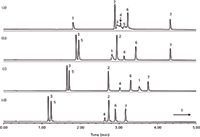
Figure 2: Comparative chromatograms on the separations of seven acidic, basic, and neutral drugs using (a) regular C18 and (bâd) charged surface hybrid C18, phenyl-hexyl, and fluoro-phenyl columns (all 50 mm à 2.1 mm, 1.7 µm). Mobile-phase A: 0.1% formic acid in water; mobile-phase B: acetonitrile; gradient: 5â95% B in 5 min; flow rate: 0.5 mL/min; detection: UV absorbance at 254 nm. Peaks: 1 = 1-pyrenesulfonic acid, 2 = flavone, 3 = imipramine, 4 = fenoprofen, 5 = amitriptyline, 6 = diclofenac, 7 = octanophenone. Adapted with permission from reference 17.
Preparing Fresh Reference Standard Solutions with Every Assay
It is a standard practice in pharmaceutical QC laboratories to prepare two reference standard solutions (or three in some European countries) by weighing out accurately 20–100 mg of a highly purified reference standard in separate volumetric flasks. These solutions are then analyzed to ensure their response factors are comparable (that is, < ±2%) (2,13). This is an excellent QC practice, albeit time-consuming and problematic for hygroscopic materials.
A potentially workable idea is to prepare a set of reference standard solutions and save them for later use. For instance, one can prepare hundreds of HPLC vials of a qualified reference standard solution and keep them refrigerated or frozen for later assays. For regulatory testing, the stability (shelf life) of these solutions in the chosen storage conditions must be verified and documented first.
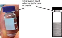
Figure 3: A picture and a drawing of an HPLC vial containing an extra layer of liquid near the neck of the vial. This extra layer of liquid is easily formed by inverting the filled vial and is physically stable. Adapted with permission from reference 14.
This idea is not really new as standard reference materials from the National Institute of Standards and Technology (NIST) and other commercial manufacturers have been available in pre-prepared, batch-processed ampoules or vials for many years. Interestingly, the use of pre-prepared standards is not widely practiced in pharmaceutical laboratories except for highly stable compounds, although many pharmaceuticals may have sufficient solution stability at low temperatures and under proper storage conditions (for example, filled vials in sealed freezer bags to prevent loss of water). By moving to this idea, more consistent potency assay data may be generated for long-term stability studies because all standard solutions would be derived from a single stock solution. A note of caution is needed here when operating under a regulatory environment where supporting documentation or validation is needed before any significant change of established procedures is implemented.
Shaking HPLC Sample Vials
In 2011, we encountered some strange sporadic HPLC assay results that took us several weeks to resolve. The episode was reported by my research associate with a molecular biology degree who was trained to shake sample vials before placing them into the autosampler to ensure sample homogeneity. For two weeks, we were unable to explain to our formulator colleagues why some of their new prototype tablets appeared to be losing 20% of potency, for some sample vials.
Fortunately, this story had a happy ending after the root cause was found. We eventually discovered that inverting sample vials could result in an extra film of liquid extract adhering to the vial septum because of the surface tension of the diluent. Ordinarily, this would not be a problem except that we were using a new model of UHPLC autosampler which drew an air gap from the headspace near the vial septum to segment the sample plug in the sampling needle. This resulted in an additional sample volume of ~0.6 µL (default air gap volume) being injected sporadically. After reporting this to the UHPLC manufacturer, the autosampler firmware was changed to draw the air gap above the vial, and we managed to publish a nice article in John Dolan's "LC Troubleshooting" column in LCGC North America (14).
The lessons learned from this experience were to shake the HPLC vial with caution, watch out for the extra liquid film underneath the vial cap, and always keep your eyes open during troubleshooting situations.
Exceptions
Frozen samples that have been "thawed" will require vortexing or shaking to ensure sample homogeneity (15).
Using Stainless Steel Ferrules for Column Connections
Service engineers from instrument companies typically install HPLC systems with stainless steel fittings and ferrules (for example, Swagelok, Waters, Parker-Hannifin, Rheodyne, Valco, and so on). While these kinds of fittings work well for most internal or external fluidic connections, they are not ideal for column connections that require frequent changes for two primary reasons: Firstly, stainless steel ferrules will only fit perfectly with the endfitting port into which they are originally "swaged," making preswaged connections noninterchangeable with different columns. Secondly, preswaged stainless fittings can reseal only 5–10 times. This is particularly significant with columns from some manufacturers that have very different endfittings and insert depths from other column brands. The simple solution is to use finger-tight polyetheretherketone (PEEK) fittings (Figure 4a), which are inexpensive and can seal well to 5000 psi for many different column types (16).
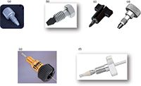
Figure 4: Modern HPLC and UHPLC fittings for column connections: (a) IDEX Health & Science (IH&S) one-piece PEEK fitting for HPLC (5000 psi); (b) IH&S VHP-320 (wrench tight to 25,000 psi); (c) IH&S-Upchurch VHP-320 with winged nut; (d) IH&S VHP-3200 finger-tight fitting (25,000 psi); (e) Thermo Scientific Viper (20,000 psi); and (f) Optimize Technologies OPTI-LOK (hand-tight to 9000 psi and wrench tight to 20,000 psi).
Finding good fittings for UHPLC was problematic in the early days (from 2004 to 2006) until the availability of improved products in the marketplace increased. The ones we found most useful are shown in Figures 4b–4f. Most of these fittings are rated to 20,000 psi by just finger-tightening (Figures 4c, 4d, and 4e) or finger tightening augmented by a quarter turn with a wrench (Figures 4b and 4f). Although these UHPLC fittings allow columns to be changed more easily and reliably (>10 make–break cycles), they also tend to be quite expensive.
Summary
In this column installment, I highlighted seven common "faux pas" or inefficient practices that should not be followed without considering alternative approaches that can offer improved chromatographic results, lower operational costs, or faster run times. Some of these alternatives may have already been adopted by experienced chromatographers, although most are probably not widely practiced. Others (not filtering mobile phases, not using buffered mobile phases, and not preparing two fresh standard solutions with every assay) may seem controversial, but can yield significant benefits and simplification if applied properly. Instead of working harder, the analytical scientist should work smarter, by questioning these outdated traditional practices, which in the context of modern HPLC can be considered "faux pas."
Acknowledgments
The author acknowledges the following reviewers and their suggestions to improve the accuracy and clarity of this manuscript: Dr. Dawen Kou and Dr. Baiwei Lin of Genentech; Dr. Davy Guillarme and Szabolcs Fekete of the University Geneva; Dr. Ron Majors of LCGC; Dr. John Dolan of LC Resources; Eric Grumbach of Waters; John Batts from IDEX; Dr. Naijun Wu of Celgene; and Dr. Tom Waeghe of Mac-Mod Analytical. The author also acknowledges input from Dr. Jack Pellett of Genentech on the use of refrigerated or frozen vials from a single stock reference standard solution and John Dolan, Tom Waeghe, Dawen Kou, and John Batts for their substantial editorial and technical input. The opinions expressed in this installment are the author's own and bear no reflections on those from LCGC or other organizations.
References
(1) L.R. Snyder, J.J. Kirkland, and J.W. Dolan, Introduction to Modern Liquid Chromatography, 3rd Ed. (John Wiley & Sons, New York, 2010), Chapter 5.
(2) M.W. Dong, Modern HPLC for Practicing Scientists (Wiley, Hoboken, New Jersey, 2006), Chapters 2,3, 5, and 9.
(3) R. Majors, LCGC North Am. 30(1), 20–25 (2012).
(4) D. Guillarme and M.W. Dong, Amer. Pharm. Rev. 16(4), 36–43 (2013).
(5) S. Fekete, D. Guillarme, and M.W. Dong, LCGC North Amer. 32(6), 420–433 (2014).
(6) S. Fekete, K. Ganzler, and D. Guillarme, J. Pharm. Biomed. Anal. 78–79, 141–149 (2013).
(7) N. Wu, A. Clausen, L. Wright, K. Vogel, and F. Bernardoni, Amer. Pharm. Rev. 11, 24–33 (2008).
(8) M.W. Dong, LCGC North Am. 31(10), 868–880 (2013).
(9) J.W. Dolan, LCGC North Am. 32(3), 188–193 (2014).
(10) M.W. Dong et al., "HPLC Column 'Standardization' in a Pharmaceutical Analysis Lab," presented at Eastern Analytical Symposium, Somerville, New Jersey, 2013.
(11) J.W. Dolan, LCGC North Am. 29(8), 652–657 (2011).
(12) M.W. Dong, LCGC North Am. 31(8), 612–621 (2013).
(13) T.S. Patel and R. LoBrutto, in HPLC for Pharmaceutical Scientists, Y.V. Kazakevich and R. LoBrutto, Eds. (Wiley, Hoboken, New Jersey, 2007), Chapter 15.
(14) M.W. Dong and K. Louie, LCGC North Am. 30(2), 112–118 (2012).
(15) J.W. Dolan, LCGC North Am. 2(11), 834–836 (1984).
(16) J.W. Batts, All About Fittings (IDEX Health & Science, Oak Harbor, Washington, 2012).
(17) K.J. Fountain, H.B, Hewitson, P.C. Iraneta, and D. Morrison, Application Note, 720003720EN, Waters Corporation, Milford, Massachusetts, 2014.
Michael W. Dong is a senior scientist in Small Molecule Drug Discovery at Genentech in South San Francisco, California. He is responsible for new technologies, automation, and supporting late-stage research projects in small molecule analytical chemistry and QC of small molecule pharmaceutical sciences. He holds a PhD in analytical chemistry from the City University of New York and a certificate in Biotechnology from U.C. Santa Cruz. He has conducted numerous courses on HPLC/UHPLC, pharmaceutical analysis, HPLC method development, drug development process, and drug quality fundamentals. He is the author of 100+ journal articles and Modern HPLC for Practicing Scientists as well as a co-editor of Handbook of Pharmaceutical Analysis by HPLC. He is a member of the editorial advisory board of LCGC North America.

Michael W. Dong

.png&w=3840&q=75)

.png&w=3840&q=75)


.png&w=3840&q=75)


.png&w=3840&q=75)


