Recent Developments in Ion-Exchange Columns for Ion Chromatography
Special Issues
A summary of the latest in new ion-exchange phases for ion chromatography, with a focus on general aspects of phase design and then a review of anion-exchange and cation-exchange columns introduced in the past few years
Ion-exchange chromatography is a relatively mature area of chromatographic separation yet advances in this technique continue unabated. This article provides a summary of the latest in new ion-exchange phases for ion chromatography. It starts by focusing on general aspects of phase design and then reviews anion-exchange and cation-exchange columns introduced in the past few years.
Ion chromatography (IC) continues to be the chromatographic technique most widely used for the separation of ionic and ionizable compounds, with a special focus on the analysis of inorganic anions, inorganic cations, small hydrophilic organic acids, and aliphatic amines. Although a number of separation modes are included under the umbrella term of ion chromatography, ion exchange is by far the most widely used technique in IC. Although use of ion-pair techniques in conjunction with reversed-phase columns remains a viable alternative to ion exchange for IC applications, ion exchange continues to be the focus of development when it comes to new stationary phases designed for specific applications involving the separation of ionic compounds. There are a number of reasons why ion exchange has proven to be the preferred separation technique in IC. These include a broad range of available selectivities, the ability to tailor selectivity for specific applications, the exceptional chemical stability of polymeric ion-exchange materials, the ability to separate ions of similar size, and rapid equilibration when operated in the gradient mode.
Stationary-Phase Architecture
Stationary-phase construction for IC columns comprises nine basic architectures: silane-based modification of porous silica substrates, electrostatic-agglomerated films on nonporous substrates, electrostatic-agglomerated films on ultrawide-pore substrates, polymer-grafted films on porous substrates, chemically derivatized polymeric substrates, polymer-encapsulated substrates, ionic molecules adsorbed onto chromatographic substrates, step-growth polymers on polymeric substrates, and hybrid materials based on a combination of a silane-modified silica substrate with a polymeric exterior surface coating. Five of these — electrostatic-agglomerated films on ultrawide-pore substrates, polymer-grafted films on porous substrates, chemically derivatized polymeric substrates, polymer-encapsulated substrates, and step-growth polymers on polymeric substrates — represent the architectures most widely used in recently introduced phases. Hence it's worth taking a deeper look at these five architectures to better understand their relative strengths and weaknesses.
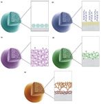
Figure 1: Ion chromatography stationary-phase architectures most widely used in recently introduced phases: (a) electrostatic agglomerated ultrawide-pore substrates, (b) polymer-grafted film on porous substrates, (c) chemically derivatized polymeric substrates, (d) polymer-encapsulated substrates, and (e) step-growth polymers on polymeric substrates.
Electrostatic agglomerated films on ultrawide-pore substrates: For the most part, electrostatic agglomerated films on nonporous substrates have been largely supplanted by higher capacity versions utilizing ultrawide-pore substrates (Figure 1a). By using an architecture similar to that based on nonporous substrates, but making use of substrates with pore sizes in the 100–300 nm range, it is possible to construct materials with substantially higher capacity (1). The pore size of the ultrawide-pore substrate and the particle size of the colloidal ion-exchange material are chosen such that the pore size is large enough to accommodate a coating of ion-exchange colloid on both the interior and the exterior surfaces of the porous substrate. With the optimal ratio of substrate pore size to colloidal particle size, the resulting material can exhibit 6–8 times the capacity achievable on an identical particle size nonporous substrate (that is, 30–150 µEq/mL for materials using an ultrawide pore format compared to 5–30 µEq/mL for materials using a nonporous format). Given the increasing importance of high capacity chromatographic materials in IC and the availability of high capacity suppressor devices, this stationary phase architecture has seen wide application in recent years.
Polymer-grafted films on porous substrates: This type of material (Figure 1b) is widely used to prepare high capacity packings where crosslinking is not required for selectivity control. Chromatographic materials of this sort are prepared through attachment of polymer strands to the surface of a substrate (2,3). To prepare such materials, the substrate is either prepared with polymerizable groups on the surface, the surface is modified to introduce polymerizable groups, or the surface is modified to introduce an initiator species. Resin, monomer (or monomers), and initiator are then allowed to react to produce a composite polymer graft with polymer strands projecting from the substrate surface. Because including a crosslinking monomer into the reaction mixture will cause the reaction mixture to form a gel with substrate particles suspended in the gel, this synthesis approach precludes the use of crosslinking monomers. The fact that no crosslinker can be used in grafted polymer films limits the ability to control selectivity in such grafted films. This architecture is mainly used in applications that require a stationary phase with relatively high capacity and high water content. Such materials can be prepared from either polymer-based or silica-based substrates, but in practice nearly all such materials are produced using polymeric substrates.
Chemically derivatized polymeric substrates: This type of material (Figure 1c) tends to involve proprietary synthesis techniques, so the actual chemistry used for the derivatization reaction is generally unknown in commercial products. In general, chromatographic materials of this sort have substantial capacity because functional groups are not necessarily limited to the surface of the substrate. Such materials have become popular in recent years as column capacities have shifted higher. The critical difficulty with this stationary-phase synthesis methodology is the requirement that the derivatization be constrained to the surface to achieve good chromatographic performance. Reactions that take place beneath the surface in the dense polymer matrix of the substrate will exhibit sluggish mass transport and relatively poor chromatographic performance. Early examples of this stationary-phase architecture exhibited relatively poor performance but newer materials such as the IC SI-52 4E column (Showa Denko) illustrate that high performance materials can indeed be constructed in this manner.
Polymer-encapsulated substrates: Professor Gerard Schomburg of the Max Planck Institute in Mulheim-Ruhr, Germany, pioneered this type of material (Figure 1d) as a means of preparing materials for reversed-phase chromatography using alumina as the base material. Synthesis of polymer-encapsulated materials is accomplished by combining the substrate, a preformed polymer with residual double bonds, and a suitable free radical initiator dissolved in an appropriate solvent, stripping off the solvent to leave a polymer film on the surface of the substrate, and then curing the film at elevated temperature to yield a crosslinked film permanently encapsulating the substrate. The advantage of this architecture is that chemical attachment to the surface of the substrate is not required, allowing it to be used with inorganic substrates not amenable to covalent modification. Although initially developed as a means of producing a reversed-phase material based on alumina, the technique was later adapted by Schomburg's group as a means of preparing a weak-cation-exchange phase using a preformed butadiene-maleic acid copolymer as the encapsulating polymer (4). The first commercial introduction of stationary phases based on this approach brought about a major shift in stationary-phase design as applied for the separation of inorganic cations. Before the introduction of this new synthesis method, nearly all separation products were based on strong-acid cation-exchange stationary phases. Since that time, nearly all stationary phases utilized for the separation of inorganic cations have used weak-cation-exchange carboxylic acid–based stationary phases. A disadvantage of this synthetic approach is the possibility of swelling and shrinking of the phase during gradients or temperature programming depending on the cure conditions of the film. In addition, even if the coating is free of surface defects, alkaline reagents can still attack the underlying silica by penetrating to the surface coating, resulting in bed collapse.
Step-growth polymers on polymeric substrates: This simple yet versatile synthesis method has seen wide use in recent years (Figure 1e). Over the past decade, more than 10 anion-exchange columns have been introduced using this stationary-phase architecture. This synthesis approach is a hybrid of the first and second architectures described above. Stationary-phase preparation begins with functionalization of a wide-pore substrate to introduce anionic surface charges (5,6). Then, an epoxy-amine copolymer is formed in the presence of this material, producing an amine rich "basement" polymer that is electrostatically bound to the resin surface. Finally, in a repetitive series of reactions, this polymer-coated substrate is allowed to react with first an epoxy monomer containing at least two epoxy functional groups and then an amine or ammonia. By using a primary amine or ammonia or a trifunctional epoxy monomer, it is possible to introduce branch sites. The resulting surface composite can be exceptionally hydrophilic because the epoxy monomer and the amines used in its construction contain only aliphatic substituents. And yet, such materials are completely compatible with high-pH mobile phases that tend to damage most hydrophilic stationary phases.
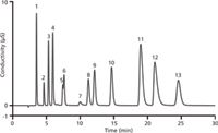
Figure 2: Isocratic separation of sulfur species and inorganic anions. Column: IonPac AS25, 4 mm; eluent: 37 mM potassium hydroxide; eluent source: EGC III KOH; flow rate: 1 mL/min; injection volume: 25 µL; temperature: 30 °C; detection: suppressed conductivity, ASRS 300 4 mm, AutoSuppression recycle mode, 92 mA. Peaks: 1 = fluoride, 2 = bromate, 3 = chloride, 4 = nitrite, 5 = bromide, 6 = nitrate, 7 = carbonate, 8 = sulfite, 9 = sulfate, 10 = iodide, 11 = thiocyanate, 12 = perchlorate, 13 = thiosulfate.
New Anion-Exchange Chromatography Columns
A number of new anion-exchange columns were introduced in the last few years. Thermo Fisher Scientific extended its Dionex IonPac stationary phases with the introduction of IonPac AS25 polymeric anion-exchange columns with alkanol quaternary ammonium functionality. This column uses the type 5 architecture described above but unlike prior versions of this chemistry it uses alternating reactions with a di-epoxide and a di-tertiary amine to produce linear projecting strands. Earlier versions of this architecture had relatively poor selectivity for sulfate and sulfite. By controlling the gap between the tertiary amine sites in the polymer chain, the selectivity for these two anions can be controlled. Figure 2 shows an example application of this column for the analysis of sulfur species, an application not possible on previous columns using this architecture.
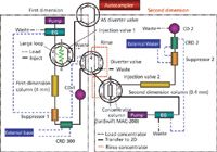
Figure 3: Two-dimensional ion chromatography instrumental setup.
In addition, two new specialty high capacity columns, the IonPac AS24A (4 mm i.d.) and IonPac AS26 (0.4 mm i.d.) columns (Thermo Fisher Scientific), were introduced. These columns are specifically designed for analysis of haloacetic acids via two-dimensional (2D) IC. The technique of 2D chromatography uses two columns in a switching arrangement and is useful to achieve improved separations of complex mixtures by selecting (heart-cutting) unresolved components from the primary column and further separating them on the secondary column that has a different selectivity than the primary column. The technique is also useful for samples where there is a mismatch in concentration levels such that quantitation of the smaller concentration solutes is jeopardized. Figure 3 shows a schematic representation of the instrumental setup that allows these two columns to be used in combination for the analysis of trace levels of haloacetic acids in the presence of high levels of common inorganic anions such as chloride and sulfate. On the left side of the schematic is shown the configuration for the 4-mm columns. Analytes of interest are separated at least partially on the 4-mm column after which they pass through suppressor 1, a carbonate-removal device (CRD), a conductivity cell, the diverter valve, and finally onto a concentrator column located in injection valve 2 where the analyte bands are refocused before reinjection onto a capillary column. Because the second-dimension column has a 100-fold smaller cross-sectional area, a 100-fold increase in detection sensitivity is achieved compared to using columns of identical internal diameter for both portions of the separation. Figure 4 shows an example separation using these two columns in this 2D IC application. The two columns were developed in collaboration with a team of scientists from the United States Environmental Protection Agency (USEPA). Because drinking water samples vary widely in terms of ionic composition and ionic strength, the first of these two columns used in the 2D configuration was developed in a high-capacity format. The second column is of somewhat lower capacity as most of the matrix components are diverted to waste rather than being passed through the second column. Both columns use type 5 architecture to achieve good selectivity and excellent peak shape for haloacetic acids, which are highly polarizable anions and tend to exhibit poor peak shape on most polymeric anion-exchange columns.
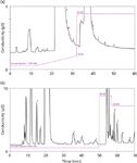
Figure 4: Two-dimensional ion chromatography analysis of haloacetic acids: (a) D1 columns: Dionex IonPac AG24A, AS24A, 4 mm; flow rate: 1.0 mL/min; eluent: potassium hydroxide, 7 mM (0â12 min), 7â18 mM (12â32 min), step to 65 mM at 32.1 min; suppressor: Dionex ASRS 300, 4 mm; current: 161 mA; loop: 500 µL; oven: 15 °C. (b) D2 columns: Dionex IonPac AG26, AS26, 0.4 mm; flow rate: 0.012 mL/min; eluent: potassium hydroxide, 6 mM (0â50 min), step to 160 mM at 50 min, step to 130 mM at 57 min; suppressor: Thermo Scientific Dionex ACES anion capillary electrolytic suppressor; current: 25 mA; concentrator: MAC-200; oven: 14 °C. Matrix: A. HIW (250 ppm Cl, 250 ppm SO4, 150 ppm HCO3, 10 ppm NH4Cl). Peaks: 1 = MCAA, 2 = MBAA, 3 = DCAA, 4 = BCAA, 5 = DBAA, 6 = TCAA, 7 = BDCAA, 8 = CDBAA, 9 = TBAA.
New Cation-Exchange Chromatography Columns
In the area of cation-exchange columns, Metrohm recently introduced two new cation-exchange columns: the Metrosep C5 column and more recently, the Metrosep C6 column. The Metrosep C5 is a strong-acid cation column with a polystyrene–divinylbenzene substrate and is based on type 3 stationary-phase architecture. The column allows the separation of transition metal cations when using chelating mobile-phase components, as shown in Figure 5. This column is designed to be used in conjunction with postcolumn addition of colorimetric metal chelating agents such as 4-pyridylazoresorcinol (PAR), allowing low parts-per-billion detection limits. In addition, Metrohm also recently introduced the Metrosep C6 column, which is based on type 4 stationary-phase architecture. The column is well-suited to samples with analytes exhibiting extreme concentration differences. The utility of the column can be demonstrated, for example, by environmental water samples, where low levels of ammonium can be quantified in the presence of 12,500-fold higher concentrations of sodium. With the Metrosep C6 column, all of the more common alkali metals and alkaline earths can be determined in a single run (see Figure 6).
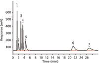
Figure 5: Ion chromatography separation of transition metal cations. Column: 150 mm à 4.6 mm Metrosep C5; eluent: 6 mM oxalic acid, 3 mM citric acid adjusted to pH 4.2 (KOH); flow rate: 1 mL/min; PCR reagent: 0.15 mM 4-pyridylazoresorcinol, 0.4 M ammonium hydroxide, 80 mM nitric acid; PCR flow rate: 0.5 mL/min; detection: absorbance (vis) at 530 nm. Peaks: 1 = copper (5.00 mg/L), 2 = nickel (3.00 mg/L), 3 = zinc (4.00 mg/L), 4 = cobalt (5.00 mg/L), 5 = lead (30.0 mg/L), 6 = manganese (4.00 mg/L), 7 = cadmium (7.00 mg/L).
Another new cation-exchange column targeting suppressed IC applications is the IonPac CS19 column (Thermo Fisher Scientific). This weak-cation-exchange column makes use of an ultrawide-pore substrate with type 2 stationary-phase architecture. It is the first column in the IonPac cation-exchange column family to use ultrawide-pore substrate morphology. The substrate enables exceptionally good chromatographic performance for inorganic cations while providing excellent peak shape for common aliphatic amines, which is more difficult to achieve with higher surface area media with small pore size.
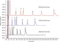
Figure 6: Ion chromatography separation of alkali metals and alkaline earths. Column: Metrosep C6, 4 mm; eluent: 1.7 mM nitric acid, 1.7 mM dipicolinic acid; flow rate: 0.9 mL/min; temperature: ambient; detection: conductivity. Peaks: 1 = lithium, 2 = sodium, 3 = ammonium, 4 = potassium, 5 = magnesium, 6 = calcium.
Columns with a Smaller Internal Diameter
In addition to the new columns mentioned above, there is an increasing trend toward the use of smaller internal diameter columns in IC. Microbore (1–2 mm i.d.) and capillary columns (<1 mm i.d.) have two main advantages. The first is higher sensitivity in analyses with a limited amount of sample. If the same mass of sample is injected onto a column with a smaller internal diameter, the peak height will increase, perhaps allowing one to measure smaller concentrations of substance. Second, to maintain the same separation time, the linear velocity must be the same. For a column with a smaller internal diameter, this means that the flow rate must be decreased proportionally to the inverse radius-ratio squared. The result is lower usage of solvent.
Over the past few years there has been a significant expansion in the range of column chemistries available in 2-mm i.d. columns. Metrohm added four new chemistries to its 2-mm column portfolio: the Metrosep A Supp 10, Metrosep A Supp 15, Metrosep A Supp 16, and Metrosep C4 column chemistries. Thermo Fisher Scientific added the IonPac AS24A, IonPac AS25, and IonPac 26 column chemistries to its already extensive range of 2-mm column chemistries. In addition, over the past few years, Thermo Fisher Scientific has expanded its column portfolio to include more than 20 different column chemistries in capillary (400 µm i.d.) column formats.
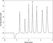
Figure 7: Fast ion chromatography analysis of common inorganic anions. Column: 100 mm à 4.6 mm TSKgel SuperIC-Anion HS; eluent: 3.8 mM sodium bicarbonate and 3 mM sodium carbonate; flow rate: 1.5 mL/min; injection volume: 25 µL; temperature: 30 °C; detection: suppressed conductivity, ASRS 300 4 mm, AutoSuppression, recycle mode, 77 mA. Peaks: 1 = fluoride (1 ppm), 2 = chloride (3 ppm), 3 = nitrite (5 ppm), 4 = bromide (10 ppm), 5 = nitrate (10 ppm), 6 = phosphate (15 ppm), 7 = sulfate (15 ppm).
Columns Based on Reduced-Particle-Size Media
With the advance of ultrahigh-pressure liquid chromatography (UHPLC), the high performance liquid chromatography (HPLC) community has seen a significant increase in the number of small-particle-size columns available for HPLC applications. In recent years, this trend has begun to influence new column introductions in IC as well. Smaller particles tend to provide improved separation efficiencies compared to larger particles and allow the use of shorter columns to achieve similar separations. For example, Tosoh Bioscience recently introduced the TSKgel SuperIC-Anion HS column, which it describes as a "hypervelocity anion analysis column." Based on 3.5-µm particle size media, the new column is available in a 100 mm × 4.6 mm format, optimized to take advantage of the highest plate count possible with small particle media for fast analysis of common inorganic anions (see Figure 7). In addition, Shodex has introduced IC SI-35 4D column, which is based on 3.5-µm particle size polyvinylalcohol media in a 150 mm × 4 mm column format. Taking advantage of the small particle size and associated high chromatographic efficiency, this phase enables fast analysis of the common anions and oxyhalide disinfection by-products in less than 14 min. The same column is useful for the analysis of a number of common aliphatic carboxylic acids. Following the same trend, over the past 12 months, Thermo Fisher Scientific has made three popular column chemistries available with 4-µm particle size substrates: the IonPac AS18-4µm, IonPac AS11-HC-4µm (both using type 1 architecture), and IonPac CS19-4µm chemistries. Each of these three columns was separately optimized targeting specific application areas. The IonPac AS18-4µm column was optimized for fast analysis of common inorganic anions; the IonPac AS11-HC-4µm column was optimized for high-resolution separations of inorganic anions and carboxylic acids; and the IonPac CS19-4µm column was optimized for high-resolution separations of inorganic cations and aliphatic amines.
Conclusions
New ion-exchange columns for IC continue to be introduced each year, as improvements in column selectivity progress. The growth in ion exchange is spurred by new environmental regulations and growing concerns over possible food contamination. Most new columns have been packed with rugged polymeric-based materials, and this trend will undoubtedly continue. Most ion-exchange columns tend to have relatively high ion-exchange capacities. Increased ion-exchange capacity is important for challenging applications where analytes span a wide concentration range. A trend toward the use of columns with smaller internal diameters is clearly apparent with the 2-mm i.d. columns now widely available and capillary column formats available in most common column chemistries. In addition, particle sizes for IC columns have decreased in recent times, following the trend in HPLC and UHPLC.
References
(1) T. Stevens, U. S. Patent 4,351,909, May 21, 1981.
(2) D. Jensen, J. Weiss, M.A. Rey, and C.A. Pohl, J Chromatogr. 640(1–2), 65–71 (1993).
(3) J. Riviello, M. Rey, J. Jagodzinski, and C.A. Pohl, U. S. Patent 5,865,994, February 2, 1999.
(4) P. Kolla, J. Köhler, and G. Schomburg, Chromatographia 23, 465 (1987).
(5) C. Pohl and C. Saini, J Chromatogr. A 1213(1), 37–44 (2008).
(6) C.A. Pohl and C. Saini, U. S. Patent 7,291,395, November 6, 2007.
Christopher Pohl is the Vice President of Chromatography Chemistry in the Chromatography & Mass Spectrometry Division of Thermo Fisher Scientific. Christopher joined Dionex, now part of Thermo Fisher Scientific, in 1979 where the focus of his work has been new stationary phase design. He is an author or coauthor of 50 US patents in a number of areas, including separation methods, stationary-phase design, suppressor technology, solid-phase extraction, capillary electrophoresis techniques, and accelerated solvent extraction (ASE). He is the author or coauthor of four book chapters and more than 95 scientific papers published in peer reviewed scientific journals. He received his BS in Analytical Chemistry from the University of Washington in 1973.

Christopher Pohl

Sorbonne Researchers Develop Miniaturized GC Detector for VOC Analysis
April 16th 2025A team of scientists from the Paris university developed and optimized MAVERIC, a miniaturized and autonomous gas chromatography (GC) system coupled to a nano-gravimetric detector (NGD) based on a NEMS (nano-electromechanical-system) resonator.

.png&w=3840&q=75)

.png&w=3840&q=75)


.png&w=3840&q=75)


.png&w=3840&q=75)


