Ion Chromatography Yesterday and Today: Detection
Special Issues
A look at the current status of detection in ion chromatography, focusing on the most popular detectors in IC: the conductivity detector and the charge detector
Here, we look at the current status of detection in ion chromatography (IC), focusing on the most popular detectors in IC: the conductivity detector and the charge detector. Conductivity detection, including the capacitively coupled contactless conductivity detection, is discussed. Charge detectors developed in the author's laboratory are shown to complement conductivity detectors.
The great power of ion-exchange chromatography to bring about complex separations was aptly demonstrated by Moore and Stein (1); this work eventually led to their receiving the 1972 Nobel laurel. They were able to separate all 50 amino acids in 175 h (slightly more than a week) using a 100 cm × 0.9 cm column packed with 25–37 µm cation-exchange resin, at a flow rate of 67 µL/min. They recognized that not only pH affects the retention of amino acids by controlling their ionization but that temperature can also profoundly affect such equilibria. They used a pH gradient from 4.25 to 11.0, and temperatures of 25–75 °C at various points during the profile. Interestingly, in this paper Moore and Stein thanked William Bauman of the Dow Chemical Company for supplying them with an ultrafine cation-exchange resin (not then commonly available).
Detection in the Moore and Stein work was off-line with fractions collected and reacted with ninhydrin before colorimetric measurement. Two decades later, amino acid analyzers with postcolumn ninhydrin reaction and flow-through colorimeters and high performance liquid chromatography (HPLC) with flow-through UV absorbance detectors were in existence. For the analysis of simple inorganic ions, however, many major anions of interest (such as sulfate) have no useful optical absorption or, in the case of chloride and other anions, absorb very poorly except at very low wavelengths where eluents are also likely to absorb. Conductivity detectors, on the other hand, can sense all ions, but there was no simple way to use them. For analyte ions to be eluted from available (high-capacity) ion-exchange columns in a reasonable period, other (eluent) ions are needed in significant concentrations. With a high conductivity background, minor conductivity changes accompanying the elution of analyte ions would have been impossible to detect. It was the genius of Small, Stevens, and Bauman (2) that solved this problem through a unique solid-phase postcolumn reactor that literally made the separation visible to the conductivity detector, and a unique electrostatically agglomerated stationary phase that was both efficient and of sufficiently low capacity to be used in that configuration. The stationary phase was akin to pellicular ion-exchanger stationary phases proposed earlier by Horvath and colleagues (3) but far more robust and functionally no different in its attributes than present-day superficially porous particles.
The original discovery and the principles of suppressed conductometric ion chromatography (IC) are discussed in detail by Small in the present issue (4). The solid-phase postcolumn reactor survives in the form of a unique three-position alternating revolving device (5) but has largely been supplanted by electrodialytically regenerated membrane devices (6). Here, we focus on the evolution and the current status of the two detectors unique to IC: the conductivity detector and the charge detector.
Conductivity Detection
Conductivity detection has been and continues to be the mainstay of IC. In the analyte concentration range of interest, conductivity is linearly related to ionic concentration: The slope is dependent on the specific ion or ions. At high concentrations, the response is less than linear, but this area typically is not of interest in IC.
Conductivity detectors are fundamentally of two types, differentiated by whether or not the electrodes are in galvanic contact with the solution. It is possible to make measurements from outside a glass or polymeric tube without electrodes contacting the liquid. Currently available IC equipment does not yet use very small capillaries (<100 µm bore), whether packed or wall-coated. With such dimensions, it is not practical to make measurements in a separate cell, external to the separation system, because of excessive dispersion from connecting tubing and other flow-path components. The measurement must be made directly on-capillary. Although fine wire electrodes in galvanic contact with the solution inserted through holes drilled through the capillary walls (7) or at the end of the capillary (8) have been demonstrated for capillary electrophoresis (CE) systems, a more elegant and generally applicable solution is capacitively coupled contactless conductivity detection (C4D).
In C4D, a pair of ring-shaped electrodes is put on the separation or measurement capillary ~1 mm apart. An excitation voltage is applied to one electrode; this voltage usually has a frequency of several hundred kilohertz, but some operating at a frequency as low as 200 Hz have been reported (9). This excitation signal is capacitively coupled through the capillary walls to the solution inside and travels to the other electrode. There are many different approaches to measure the conductance. In the simplest approach, a current-to-voltage converter is connected between the pickup electrode and ground. The resulting signal is amplified and rectified and is directly proportional to the solution conductance. Kuban and Hauser have repeatedly reviewed design and application of C4D techniques; the latest appeared in 2013 (10). A readily available inexpensive capacitance-to-voltage high resolution digital converter behaves very much like a C4D (11,12) but saturates at specific conductance values of ~100 µS/cm. As yet, C4D has not been much used in conventional IC. But it has many virtues and it is merely a matter of time before it is used more extensively in IC.
In galvanic conductivity measurements, there are two basic arrangements: a four-electrode and a two electrode arrangement. The four-electrode arrangement uses an outer pair of electrodes to apply a constant current through the system and then the voltage drop across the inner pair is monitored; this voltage drop is reciprocally related to the conductance. Although the four-electrode technique is the gold standard for resistance measurements in the solid state and used in some CE instruments, it has seen little use in IC.
A common geometry for a flow-through electrical conductivity detection cell consists of two disk-shaped stainless steel electrodes (~1–1.5 mm in diameter) that are spaced ~1 mm apart, or two ring-shaped electrodes spaced 4–5 mm apart. A temperature sensor, usually a low thermal mass thermistor, is also placed in the thermal block containing the cell to measure and correct for the temperature dependence of the measured conductance. A typical correction coefficient assumes that conductivity increases 1.7% per Celsius degree, but most detectors allow user-selectable temperature compensation values to be input. (Two major vendors of IC equipment both specify temperature constancy better than 0.001 °C. We remain somewhat skeptical about how well these dry cell block temperature specifications relate to the temperature constancy of the flowing liquid. If thermal noise were the only noise, in a measured background conductance of 1 µS/cm, the noise level will be 20 pS/cm, an order of magnitude less than the 100–300 pS/cm observed in practice. As a reference point, the best refractive index detectors in HPLC claim a temperature constancy of 0.005 °C.) In the simplest arrangement, an alternating voltage, 1–20 kHz in frequency, is applied across the electrodes and the resulting current is measured, rectified, and converted to a voltage signal. The ratio of the current to applied voltage is the conductance.
Both the above measurements are, however, affected by the capacitance at the electrode–solution interface. A bipolar pulse conductance measurement technique is not affected by the presence of capacitance, either serially or in parallel to the resistive element. Two successive voltage pulses of equal magnitude but opposite polarity are applied to the measurement cell. The current passing through the cell at the end of the second pulse in measured. This is the technique typically used in high-end conductivity detectors. DC voltages are generally not used, to avoid electrochemical processes at the electrodes. Conductometry is not an electrochemical technique — no chemistry occurs at the electrodes. However, when the background conductance is low, as with hydroxide eluents or a carbonate eluent with a carbon dioxide removal device, DC measurements have been shown to provide a very simple inexpensive alternative (13). In the stopped flow mode, a DC detector serves as a chronoamperometric device. The temporal signal profile reflects the ionic mobility of the anion in the cell; this helps identify a peak beyond retention time (14).
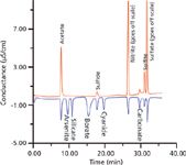
A major shortcoming of suppressed conductometric IC is its reduced response to weak acids. For acids with a pKa ≤ 7, practically no response is observed. On the other hand, hydroxide eluent nonsuppressed IC can provide a response (15); however, chromatographically such eluents are essentially unusable with real samples. Ideally, the best of both worlds can be attained if, after the first (conventional) suppressed conductivity detector, a small amount of hydroxide (such as sodium hydroxide) is introduced electrodialytically (16) or by Donnan breakdown (17) and then detected with a second detector. The detection principle of this second detector will be the same as that in a nonsuppressed hydroxide eluent IC. The results of such a two-dimensional detection are shown in Figure 1. This is a powerful adjunct to conventional suppressed IC. While not commercially available, commercial systems are now available that have two independent IC systems, each equipped with an eluent generator. Such systems can be configured to carry out such dual detection. Note that the ratio of the peaks in the two detectors is indicative of the pKa of the acid and thus serves as an independent identifier.

Figure 1: Two-dimensional gradient hydroxide elution ion chromatogram. Red trace: suppressed conductivity detector; blue trace: second-dimension detector (after baseline offset, background ~25 µS/cm). Column: AS11HC; mobile-phase gradient: 0â3.0 mM KOH in 10 min, hold at 3.0 mM until 15 min, ramp to 10 mM 15â20 min, ramp to 20 mM 20â30 min, ramp to 30 mM 30â40 min. Analyte amounts: 6.25 nmol for nitrate, borate, acetate, and sulfate; 12.5 nmol for the others, except carbonate (deliberately not added). Adapted from reference 17 with permission.
Charge Detection
The charge detector (18) is the most recently introduced detector for IC. It is generically responsive to ions but the detection principles differ from those of a conductivity detector and hence a charge detector is a good adjunct to the latter. The basic configuration of the charge detector is the same as that of an electrodialytic suppressor except that it uses a cation-exchange membrane (CEM), which is held negative, and an anion-exchange membrane (AEM), which is held positive, while the suppressor effluent flows between the two membranes. The current between the electrodes (applied voltage is 2–12 V DC, typically 6 V DC) is the analytical signal. There is a small background current from the residual ionic impurities in the water and also from the autodissociation of water itself.

Figure 2: Basic schematic for the charge detector.
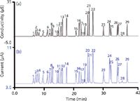
When an electrolyte (for suppressed anion IC this is necessarily an acid, but in principle it can be any electrolyte) moves into the detector, H+ and X-, proceed through the CEM and AEM, respectively, to the oppositely charged electrodes; it is the charge carried by these ions that is measured (Figure 2). This allows universal calibration for fully ionized electrolytes given that 1 µM SO42- produces the same signal as 2 µM Cl-, and so on. The charge detector is a destructive detector: It is essentially a deionizer; the charge transport occurring during deionization is what is measured. Interestingly, compared to the conductivity detector, the charge detector has a relatively higher response for weak electrolytes. Whereas a conductivity detector responds only to the ionized portion of a weak electrolyte, as deionization occurs in the charge detector, more of the undissociated material ionizes to maintain equilibrium. To what degree it is ultimately deionized depends on the applied electric field and the residence time in the detector. As such, the effect of the eluent flow rate (reciprocally related to the detector residence time) is far greater for a weak acid anion than a strong acid anion. Even at normal chromatographic flow rates, the charge detector has enhanced response for weak electrolytes like organic acids, as shown in Figure 3.

Figure 3: Gradient hydroxide elution on a 250 mm à 0.4 mm, 4-µm AS11HC column with a flow rate of 15 µL/min and temperature set at 30 °C. (a) conductivity detector, (b) charge detector. Injection volume: 0.4 µL. Peaks: 1 = quinate (10 mg/L), 2 = fluoride (3 mg/L), 3 = lactate (10 mg/L), 4 = acetate (10 mg/L), 5 = propionate (10 mg/L), 6 = formate (10 mg/L), 7 = butyrate (10 mg/L), 8 = methanesulfonate (10 mg/L), 9 = pyruvate (10 mg/L), 10 = valerate (10 mg/L), 11 = monochloroacetate (10 mg/L), 12 = bromate (10 mg/L), 13 = chloride (5 mg/L), 14 = nitrite (10 mg/L), 15 = trifluoroacetate (10 mg/L), 16 = bromide (10 mg/L), 17 = nitrate (10 mg/L), 18 = carbonate (20 mg/L), 19 = malonate (15 mg/L), 20 = maleate (15 mg/L), 21 = sulfate (15 mg/L), 22 = oxalate (15 mg/L), 23 = tungstate (20 mg/L), 24 = phosphate (20 mg/L), 25 = phthalate (20 mg/L), 26 = citrate (20 mg/L), 27 = chromate (20 mg/L), 28 = cis-aconitate (20 mg/L), 29 = trans-aconitate (20 mg/L). (Courtesy of Thermo Scientific.)
Conclusions
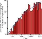
Undoubtedly, as has been proven in the past, IC and its modes of detection will continue. In Figure 4, we plot the number of documents Google Scholar retrieves as having the exact phrase "Ion Chromatography" in the title. The best fit to an asymptotical approach to a plateau model is indicated by the solid line. The predicted plateau ordinate value is 420, which would suggest that we are only two-thirds of the way to the plateau; when we reach that, the time for the next paradigm-shifting technology will have arrived.

Figure 4: Number of documents retrieved by Google Scholar with the phrase "Ion Chromatography" in the title. The solid line indicates the best fit to an asymptotic approach to a plateau. Data from 2012 are incomplete and were not used in the fit.
Acknowledgments
We thank Hamish Small first of all for planting the seed from which this tree has grown. We also thank him for sharing a draft version of his article that also appears in this issue. We are indebted to Kannan Srinivasan, Yan Liu, Christopher Pohl, and Andrea Willie for their generous and prompt help with sought-after information. We apologize that space constraints precluded much else that should otherwise have been included.
References
(1) S. Moore and W.H. Stein, J. Biol. Chem. 192, 663–681 (1951).
(2) H. Small, T.S. Stevens, and W.C. Bauman, Anal. Chem. 47, 1801–1809 (1975).
(3) C.G. Horvath, B.A. Preiss, and S.R. Lipsky, Anal. Chem. 39, 1422–1428 (1967).
(4) H. Small, LCGC North Amer. 31(S4b), 8–15 (2013).
(5) Metrohm Corporation web site, http://www.youtube.com/watch?v=8KQktLNIHf8&noredirect=1, accessed March 2013.
(6) Thermo Scientific. Advances in chemical suppression. http://www.dionex.com/en-us/webdocs/61381-Bro-SuppressorHistory-22Dec08-LPN1855-01.pdf, accessed March 2013.
(7) X. Huang, T.K. Pang, M.J. Gordon, and R.N. Zare, Anal. Chem. 59, 2747–2749 (1987).
(8) X. Huang and R. N. Zare, Anal. Chem. 63, 2193–2196 (1991).
(9) S. Pencharee, P.A. Faber, P.S. Ellis, P. Cook, J. Intaraprasert, K. Grudpan, and I.D. McKelvie, Anal. Meth . 4, 1278–1283 (2012).
(10) P. Kuban and P.C. Hauser, Electrophoresis 34, 55–69 (2013).
(11) M. Takeuchi, Q.Y. Li, B. Yang, P.K. Dasgupta, and V. E. Wilde, Talanta 76, 617–620 (2008).
(12) I.K. Kiplagat, P. Kubán, P. Pelcová, and V. Kubán, J. Chromatogr. A 1217, 5116–5123 (2010).
(13) D. Qi, T. Okada, and P.K. Dasgupta, Anal. Chem. 61, 1383–1387 (1989).
(14) T. Okada, P.K. Dasgupta, and D. Qi, Anal. Chem. 61, 1387–1392 (1989).
(15) T. Okada and T. Kuwamoto, Anal. Chem. 57, 829–833 (1985).
(16) A. Sjögren and P.K. Dasgupta, Anal. Chim. Acta 384, 135–141 (1999).
(17) R. Al-Horr, P.K. Dasgupta, and R.L. Adams, Anal. Chem. 73, 4694–4703 (2001).
(18) B.C. Yang, Y.J. Chen, M. Mori, S.I. Ohira, A.K. Azad, P.K. Dasgupta, and K. Srinivasan, Anal. Chem. 82, 951–958 (2010).
Purnendu K. (Sandy) Dasgupta is the Jenkins Garrett Professor of Chemistry at the University of Texas at Arlington. He has authored over 400 journal articles and book chapters and is the inventor on 23 US patents, including several related to IC. He is the recipient of the 2011 ACS Award in Chromatography. Direct correspondence to: Dasgupta@uta.edu

Purnendu K. (Sandy) Dasgupta
Charles Phillip Shelor is a senior PhD student who defacto manages the Dasgupta Laboratory. Phillip is working on sensitive methods of urinary iodine analysis. He has authored three publications and is the recipient of the 2012 American Chemical Society Division of Environmental Chemistry Graduate Student award.

Charles Phillip Shelor
Hongzhu Liao is graduate student in chemistry at the University of Texas at Arlington. Hongzhu focuses on new methods in ion chromatography, especially the detection of weak acids.

Hongzhu Liao

Sorbonne Researchers Develop Miniaturized GC Detector for VOC Analysis
April 16th 2025A team of scientists from the Paris university developed and optimized MAVERIC, a miniaturized and autonomous gas chromatography (GC) system coupled to a nano-gravimetric detector (NGD) based on a NEMS (nano-electromechanical-system) resonator.

.png&w=3840&q=75)

.png&w=3840&q=75)


.png&w=3840&q=75)


.png&w=3840&q=75)


