Nano LC: Principles, Evolution, and State-of-the-Art of the Technique
LCGC North America
Nano LC is now widely applied in proteomics, and also is robust enough for application in fields such as pharmaceutical analysis.
In genomics, polymerase chain reaction (PCR) is used to amplify the amount of DNA and increase the signal above the limit of detection. This approach is not applicable to proteomics, however. Therefore, the intrinsic sensitivity of the analytical method applied to the analysis of biomolecules, generally liquid chromatography–mass spectrometry (LC–MS), needs to be enhanced. The miniaturization of the LC system and its interfacing with MS results in the necessary increase in sensitivity. Nano LC is at the heart of this gain in sensitivity. This column installment reflects on the principles, development, and current state of nano LC instrumentation.
History has a tendency to repeat itself. In the 1990s, genomics led to the development of an array of dedicated analytical techniques to solve the challenges in DNA identification. During the past decade, the identification and quantification of proteins and peptides in biological fluids, also known as proteomics, has necessitated similar developments. Although polymerase chain reaction (PCR) is used in genomics to amplify the amount of DNA and increase the signal above the limit of detection, it is not applicable to proteomics. Therefore, the intrinsic sensitivity of the analytical method applied to the analysis of biomolecules, generally liquid chromatography–mass spectrometry (LC–MS), needs to be enhanced. The miniaturization of LC systems that led to the development of nano LC (Table I) and its interfacing with MS is at the heart of this gain in sensitivity.
The analysis of samples as complex as those in proteomics consists of multiple steps (sampling, sample pretreatment, separation and detection, and data analysis) in which nano LC is applied as a routine part before tandem MS detection. This installment of "Innovations in HPLC" reflects on the principles, development, and current state of nano LC instrumentation.

Table I: LC columns for various applicatons
Miniaturization of LC Systems
Theory
A reduction in column internal diameter results in less chromatographic dilution and, consequently, increased concentration of the injected sample on the high performance liquid chromatography (HPLC) system. The chromatographic dilution (D) of the sample, when injected on a LC system, is expressed by the following equation (1):

where Co is the initial compound concentration in a sample (before injection into the LC system); Cmax is the final compound concentration at the peak maximum; ε is the column porosity; r is the column radius; k is the retention factor; L is the column length; H is the column plate height; and Vinj is the sample volume injected.
D increases proportionally with the square of the column radius and with the square root of the length of the column. Thus, a reduction in column diameter results in a significantly lower dilution factor, thereby increasing the concentration in the eluted peak.
Though this formula applies to isocratic elution conditions, its consequences are commonly extrapolated to gradient elution conditions. Under gradient elution conditions, dilution is partly counteracted by increasing the strength of the mobile phase over time. However, the gain in sensitivity of this effect is far smaller than what is gained by decreasing the column internal diameter. The gain in sensitivity (f) resulting from the use of a LC column with a smaller internal diameter can be approximated by the following relation (1,2):

where d1 and d2 are the diameters of the conventional and nano LC columns, respectively.
Therefore, downscaling the column used in an analytical method from 4.6 mm i.d. to 75 µm i.d. should result in an almost 4000-fold gain in sensitivity. However, such an increase in sensitivity is not readily achieved because reducing the column internal diameter has practical consequences for the entire setup. The influence of the different system parameters is discussed below.
Columns
For practical reasons, the commonly accepted standard internal diameter for nano LC columns is 75 µm. This column format provides a good compromise between sensitivity, loadability, and robustness.
Even though standard-bore LC columns have been commercially available for decades, preparation of columns with internal diameters less than 100 µm cannot be directly extrapolated from the protocol for the production of standard-bore columns. In the early days of nano LC, researchers had to manufacture their own columns because of the lack of commercially available columns. In the 1990s, the first nano LC columns became commercially available as a result of efficient packing procedures. Throughout the last two decades, the column offering has grown tremendously and nano LC columns are now available from most HPLC vendors in a range of formats and chemistries. Self-packed nano LC columns are sometimes used by research laboratories, often for economic reasons and if quality aspects are less of a concern.
Nano LC columns are predominantly packed in fused-silica capillaries. Frits strong enough to withstand ultrahigh-pressure liquid chromatography (UHPLC) pressures are used to retain the stationary phase. The frit commonly used in standard-bore columns, a stainless steel mesh in a connection, will provide too much dead volume, thus impairing the separation efficiency. Therefore, frits in nano LC columns must be prepared inside the fused-silica capillary.
Stationary phase particle sizes for nano LC columns are similar to standard HPLC columns: 5 µm, 3 µm, and now down to sub 2 µm.
Alternatives to packed columns are monolithic columns. In this type of column, a porous (silica or polymer) structure is formed throughout the column, eliminating the need for frits because the stationary phase is fixed to the column wall. These columns are predominantly used in proteomics for the analysis of extremely complex tryptic digests.
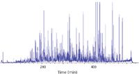
Figure 1
One of the clear trends in recent years is packing columns in longer formats. Current state-of-the-art nano LC columns are commercially available in lengths up to 50 cm (4) to provide the separation power required for these complex proteomics samples (Figure 1). Long nano LC columns combined with the use of long gradients achieve great peak capacities — going from 300 to 500 (Figure 2).
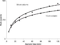
Figure 2
In general, the usability of nano LC columns also has improved by means of protective housing to shield the fragile fused silica and with integrated connectors to facilitate connections. Currently, the performance, robustness, and ease-of -use are no less than standard-bore columns.
Dead Volumes and Connections
Reducing the column internal diameter is the first of several critical steps in miniaturizing a LC system. Extracolumn peak broadening must be reduced accordingly to preserve optimal performance.
Excessive extracolumn band-broadening causes considerable loss of separation efficiency and, thereby, sensitivity. Ideally, the contribution of extracolumn peak broadening should be negligible compared to the peak broadening caused by the separation process on the separation column. Generally, a 5–10% reduction in chromatographic performance is considered acceptable (1). Extracolumn band broadening can be divided into two categories: precolumn and postcolumn band-broadening. The former causes (gradient) delay, whereas the latter causes (gradient) delay and peak broadening. The following equation can be used to approximate the effect of postcolumn dead volumes on the volume of a peak (2):

where Vp,obs is the volume of a peak as observed in the detector; Vex corresponds to the postcolumn dead volumes; and Vp is the volume of a peak eluted off a column.
The Aris-Taylor equation (3) describes the contribution of a number of chromatographic parameters to the dispersion (σ2 ) of (solute) bands in cylindrical tubes as follows:

where d and L are the internal diameter and the length of the capillary, respectively; Dm is the molecular diffusion coefficient; and u is the linear velocity of the mobile phase.
Consequently, connection tubing should be kept as short and especially as narrow as possible to minimize extracolumn band broadening and result in an acceptable increase in back pressure.
For standard nano LC operation (using 75 µm i.d. columns and flow rates around 300 nL/min), the best compromise between delay, band broadening, and back pressure is generally found using connection tubing of 10–20 µm i.d. pre- and postcolumn. Fused-silica capillaries have many advantages over stainless steel or polyether ether ketone (PEEK) tubing. Fused-silica capillaries can easily be cut to the desired length and are readily available in a range of compatible internal diameters (5–100 µm).
Making connections with silica capillaries can be a challenge to less-experienced users and often has been considered the most difficult part of setting up a nano LC system. Traditionally, fused-silica capillaries are connected to standard unions or valves using a PEEK sleeve and stainless steel nut and ferrule. If a fused-silica capillary is not flush with the valve port, dead volumes will be introduced that lead to extracolumn dispersion. The effect of dead volume on a typical nano LC separation is shown in Figure 3. Eliminating dead volumes, especially postcolumn, is key to successful nano LC analysis.
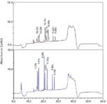
Figure 3
Several new types of connections have been introduced on the market for easy connection of columns and capillaries that are fingertight, dead volume–free by design, and rated at 1000 bar, making them UHPLC compatible.
Different Pumping Systems
Miniaturizing an LC system implies that all system components should be downscaled, including column, connecting tubing, connections, injector, and the interface to the detector (UV or MS). Nano LC columns typically require flow rates of 500 nL/min or less. Achieving reproducible flow and gradient formation requires dedicated approaches that can be divided into three categories: passive split, active split, and splitless systems.
The first-generation nano LC systems were based on conventional LC pumps equipped with a passive split. The splitter divides the high flow of the pump (hundreds of microliters per minute) between the column and restrictor. The difference in resistance of the flow through the restriction line on one side and the column (and detector) on the other side determines the split ratio. As a result, the split ratio could vary during gradient elution or when flow resistance on the column side increases, for example as a result of partial clogging of the column or of the MS interface. These systems are simple and relatively inexpensive, but compromise on flow stability and accuracy.
To overcome these problems, active split systems integrating flow-feedback have been developed (5,6). The active split systems have improved flow stability and therefore typically exhibit better reproducibility than passive split systems, but still the majority of the mobile phase is wasted.
Ideally, the flow should not be split and used directly from the pump as it is used in standard HPLC. These nano LC systems are often called "direct flow" or "splitless" systems and are available from most HPLC vendors. The direct flow systems can be divided into two groups: the "solvent refill" systems and the "continuous flow" systems. Commonly, these systems also are capable of operating at UHPLC pressures. Whereas UHPLC is mostly used to increase throughput in standard-bore LC, its use in nano LC is mostly aimed at improving separation efficiency through the use of longer nano LC columns packed with 2-µm (or smaller) particles.
Solvent refill systems deliver flow rates in the low-to-high nanoliter-per-minute range using pumps that are either syringe- or pneumatically driven. They pump the mobile phase from a single chamber or loop and have a valve to switch between aspiration and delivery phases. As a consequence, the flow through the column is stopped during the aspiration phase. Smart control algorithms ensure that the impact of the flow disruption is reduced to a minimum.
Continuous-flow pumps are more conventional pumps, having two pistons per channel. Flow disruptions are prevented as one piston delivers flow while the other refills. They achieve nano flow rates by controlling the movement of the pistons very precisely. This type of pumping system typically has an extended flow range up to 50–100 µL/min, offering more flexibility.
The latest generation nano LC pumps are becoming the workhorse of proteomics research as they offer the power and flexibility necessary to perform the most challenging separations.
Nano LC Setups
Sample introduction presents its own challenges in nano LC. Typically, sample is limited so the injection system should ensure that no sample is lost to waste.
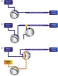
Figure 4
Direct injection setups are commonly used in conventional LC and can be used in nano LC setups (Figure 4). The sample is injected directly onto the column. Because there is only one column, there is a lower risk of losing analytes, making it popular in some proteomics laboratories. The drawbacks are the possible introduction of salts in the mass spectrometer, the low injection volume (up to 1 µL), and the lack of column protection. Peak widths at half height of approximately 6 s are commonly achieved for the analysis of peptides. Separations show excellent reproducibility with relative standard deviations (RSDs) on retention time of 0.1% or lower (Figure 5) making nano LC amenable to large-scale comparative studies.
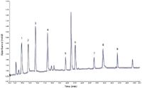
Figure 5
Different methodologies can be applied to overcome these problems with direct injection, such as off-line preconcentration, large-volume injection directly onto the separation column using specific injection conditions, and on-line preconcentration (using a trap column).
Off-line preconcentration can be performed by reducing the sample volume by evaporating or lyophilizing the sample. A pipette-based desalting step can be also incorporated.
As an alternative, it has been shown that larger sample volumes (1–5 µL) can be loaded directly onto nano LC columns in acceptable time at higher flow rates, and elution is performed at low flow rates. The gradient delay, as caused by the larger sample loop, can be minimized by bypassing the loop after the sample is loaded. This approach requires specific injection routines that may need adjustment from sample-to-sample.
Loading very complex or dirty samples like digests of cell lysates directly on the nano LC column might clog it. The use of a trapping column in a preconcentration setup remediates these limitations of direct injection.
In preconcentration setups, relatively large volumes (up to 100 µL) (7) are loaded on a trap column using a higher loading flow rate compared to the separation flow. Trap columns allow washing of salts and other hydrophilic compounds and provide efficient protection of the separation column against clogging.
Two different preconcentration set-ups are commonly used: the vented column and column switching setups (Figure 4).
In vented column setups, the switching valve is placed outside the sample stream. The valve determines the direction of the flow. During the loading phase, the eluent is directed to waste and virtually none of the flow will enter the nano separation column. When the valve is switched, the flow is then directed over the nano separation column for eluting the analytes. This setup has been used on passive split systems in which this valve is also used to switch the split on or off (2). Although vented column setups have the advantage of using a single pump, the flow is interrupted upon switching the valve, turning the spray on and off and thereby decreasing the lifetime of the spray emitter. Nowadays, control algorithms can be used to optimize the flow and gradients for best performance. Dead volumes between the trap and separation columns are minimized by the use of a nano T-piece to connect the trap and analytical columns.
Column switching setups generally require two pumps, the loading pump and the nano pump, with a trap column mounted on a switching valve. The sample is injected and concentrated on the trap column using the loading pump at a relatively high flow rate. The flow is further directed to waste during sample loading, washing salts off. During this stage, the nano pump is directly in line with the nano column. Upon valve switching, the trap column is placed in line with the nano flow to elute the analytes off the trap column and separate them on the separation column. Loading is performed with a dedicated pump, allowing a wider flow range and more extensive washing of the sample during the loading phase. Additionally, the flow through the nano LC column and the MS interface is not interrupted, thereby improving the MS signal stability and spray emitter lifetime.
To better evaluate which setup to use, it is important to keep in mind their respective advantages and drawbacks (summarized in Table II).
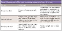
Table II: Comparison of the most commonly encountered nano LC setups
Interfacing with MS
The level of structural information provided by MS has made it the compulsory detection technique in proteomics workflows in which nano LC is routinely applied as a separation technique. Developed as an off-line technique by Wilm and Mann (8,9), nanoelectrospray ionization (nanoESI) provides an ideal interface to couple nano LC to MS, further enhancing the intrinsic sensitivity of nano LC. There are, however, two requirements that need to be fulfilled: obtaining a stable spray for flow rates of hundreds of nanoliters per minute and maintaining the separation efficiency.
Typical nanoESI sprayers are made from silica capillaries that do not conduct electricity. The simplest and most economic method of applying voltage is through a liquid junction in which an electrode makes contact with the mobile phase using a T-piece. An alternative to the liquid junction is to use coated (for example, gold) fused-silica emitters. This solution offers the advantage of eliminating the connection used in the liquid junction, but the metal coatings can deteriorate following electrical discharge.
A common alternative is packing nanoESI sprayers with stationary phase. This was initially performed for on-line concentration and desalting without aiming at separating species (10). Packing stationary phase in nanoESI emitters for separation purposes has the advantage of eliminating postcolumn dead volume almost completely. Packed emitters are often used in laboratories packing their own columns.
Their use can be complicated by Joule heating when columns are very long because part of the voltage applied to form a spray is lost due to the mobile phase electric resistance.
A relatively recent development in nano LC–MS is the introduction of chip-based structures. Chip-based systems aim at integrating the connections, columns, and spray needle in one device to make installation and operation of the nano LC system easier. As a result of the integrated connections and spray needle, extracolumn volumes are greatly reduced. The integration of all components will limit the flexibility of the setup, making them suitable for routine analysis, but not necessarily for the analysis of the most complex proteomics samples.
Conclusions and Outlook
Great technical improvements have been made from the early research setups to the fully integrated nano LC systems. Today, these direct-flow systems truly work as miniaturized LC instruments, offering UHPLC capabilities and ease of use.
Nano LC column technology has evolved into an array of columns to address the challenging analysis of the most complex samples, with lengths up to 50 cm for better separation and internal diameters smaller than 75 µm for increased sensitivity. Major progress has been made in the usability of nano LC with improved robustness and integrated connections. Researchers now have a range of instruments, columns, and setups to choose from to build their workflow and operate it with the same ease of use as any HPLC system. Today, nano LC is widely applied in proteomics laboratories. The improved performance, usability, and robustness of nano LC allow for application in other markets such as pharmaceutical and biopharmaceutical analysis.
Laurent Rieux, Evert-Jan Sneekes, and Remco Swart are with Dionex Benelux B.V., now part of Thermo Fisher Scientific, in Amsterdam, The Netherlands.
Michael Swartz "Innovations in HPLC" Editor Michael E. Swartz, Ph.D., is Principal Scientist in Analytical Development at Ariad Pharmaceuticals, Cambridge, Massachusetts, and a member of LCGC's editorial advisory board. Direct correspondence about this column to "Innovations in HPLC," at lcgcedit@lcgcmag.com.

Michael Swartz
References
(1) J.P.C. Vissers, J. Chrom. A 856, 117 (1999).
(2) H.D. Meiring, E. van der Heeft, G.J. ten Hove, and A.P.J.M. de Jong, J. Sep. Sci. 25, 557 (2002).
(3) R. Aris, Proc. R. Soc. London A 235, 67 (1956).
(4) T. Köcher, R. Swart, and K. Mechtler, Anal.Chem. 83, 2699 (2011).
(5) E. Nagele, M. Vollmer, and P. Horth, J. Chrom. A 1009, 197 (2003).
(6) J.P. Chervet, M. Ursem, and J.P. Salzmann, Anal. Chem. 68, 1507 (1996).
(7) K.J. Skogerboe, D.S. Hage, and D.J. Anderson, Anal. Chem. 65, 416R (1993).
(8) M.S. Wilm and M. Mann, Int. J. Mass Spectrom. Ion Processes 136, 167 (1994).
(9) M.S. Wilm and M. Mann, Anal. Chem. 68, 1 (1996).
(10) M.R. Emmett and R.M. Caprioli, J. Amer. Soc. Mass Spectrom. 54605 (1994).

New Study Reviews Chromatography Methods for Flavonoid Analysis
April 21st 2025Flavonoids are widely used metabolites that carry out various functions in different industries, such as food and cosmetics. Detecting, separating, and quantifying them in fruit species can be a complicated process.
Quantifying Terpenes in Hydrodistilled Cannabis sativa Essential Oil with GC-MS
April 21st 2025A recent study conducted at the University of Georgia, (Athens, Georgia) presented a validated method for quantifying 18 terpenes in Cannabis sativa essential oil, extracted via hydrodistillation. The method, utilizing gas chromatography–mass spectrometry (GC–MS) with selected ion monitoring (SIM), includes using internal standards (n-tridecane and octadecane) for accurate analysis, with key validation parameters—such as specificity, accuracy, precision, and detection limits—thoroughly assessed. LCGC International spoke to Noelle Joy of the University of Georgia, corresponding author of this paper discussing the method, about its creation and benefits it offers the analytical community.


