Multidimensional Gas Chromatography using Planar Microfluidic Devices for the Characterization of Chlorinated Degreasers in Marine Gas Oil
LCGC Europe
A practical and reliable analytical procedure that incorporates MDGC with a planar microfl uidic device as a Deans switch was developed for the characterization of chlorinated degreasers in marine gas oil.
The presence of chlorinated hydrocarbons such as trichloroethylene [CAS 79-01-6] and tetrachloroethylene [CAS 127-18-4] in marine fuels, including gas oil, can lead to accelerated corrosion to fuel pumps, valves and, ultimately, catastrophic engine failures. The two chlorinated compounds mentioned previously are used extensively as highly effective degreasers of metal parts in the automotive and other metal-working industries. The presence of these compounds in marine fuels can arise from cross-contamination of blending fuels with cutter stocks of unregulated quality, or illegal disposal of chemical waste in fuel. A practical gas chromatographic approach has been successfully developed for the accurate measurement of these compounds using a five-port planar microfluidic device configured as a Deans switch for multidimensional gas chromatography (MDGC) with a flame ionization detector (FID).
The presence of chlorinated hydrocarbons, such as trichloroethylene (TCE) and tetrachloroethylene, in marine distillate fuels such as marine gas oil can cause seal shrinkage, severe corrosion to fuel pumps, and, in the worst case, catastrophic engine failure (1,2). The greatest commercial use of trichloroethylene has been as a degreaser. The demand for trichloroethylene as a degreaser began to decline in the 1950s in favour of the less toxic 1,1,1-trichloroethane (3–5). However, 1,1,1-trichloroethane production has been phased out in most of the world under the terms of the Montreal Protocol, and, as a result, trichloroethylene has experienced some resurgence. TCE is also used as a refrigerant. Tetrachloroethylene (commonly known as perchloroethylene) is an excellent solvent for organic materials (3). It is highly stable and non-flammable. For these reasons, it is widely used in dry cleaning. It is also usually used in combination with trichloroethylene to degrease metal parts in the automotive and other metalworking industries,
Trichloroethylene and tetrachloroethylene are not natural components from petroleum refineries. Their presence in marine fuels such as gas oil or bunker fuel can originate from a variety of sources ranging from inadvertent cross-contamination of blending fuels with cutter stocks of unregulated quality; cross-contamination with industrial waste streams; or from illegal disposal of chemical waste in the fuel involved. The latter has become a prominent issue for major commercial seaports over the last decade (1).
There are three types of marine fuels, namely distillate, residual and intermediate. Distillate fuel, as the name implies, is composed of crude oil petroleum fractions separated in a refinery by distillation. Residual fuel, also known as residuum, is the remaining fraction from the distillation process. Residual fuel is also called tar or pitch. Intermediate fuel is a blend of distillate fuel and residual fuel. Boiled into a gas and then re-condensed into a liquid oil, marine gas oil is a distillate fuel, with the most common fuel grade DMA (distillate marine fuel A). DMA-grade marine fuel oil has a flash point of 60 °C and a cetane number of 50, with carbon number ranging from C5 to C26, and is comprised of well over 500 individual volatile or semi-volatile components (6). As a result, it is not possible to characterize trichloroethylene and tetrachloroethylene with single dimensional chromatography in the matrix described. Hyphenated techniques such as gas chromatography coupled with mass spectrometry (GC–MS) in selective ion monitoring (SIM) mode or headspace GC–MS can potentially be an analytical solution, albeit at a higher cost of ownership, as well as requiring a higher level of analytical skills to perform the analysis.
In this article we introduce a practical and effective integrated multidimensional gas chromatography (MDGC) system for the characterization of the aforementioned compounds of interest in marine gas oil. The analytical system incorporates a five-port planar microfluidic device to provide in-oven Deans switching with no moving parts and leak-free operation over the course of normal use. MDGC was used to reduce the potential of chromatographic interferences by taking advantage of columns with different separation mechanisms and selectivities. The extra pressure source associated with Deans switch was used further to perform backflushing of the fuel matrix and to improve overall system cleanliness and throughput. A ubiquitous flame ionization detector (FID) was used for analyte detection, quantification and ease of implementation. This article summarizes the development and analytical performance of the methodology described.
Experimental
An Agilent 6890N (Agilent Technologies) GC instrument equipped with two split–splitless inlets, two flame ionization detectors and an auxiliary pressure control module was employed for all analyses. A SilFlow five-port planar microfluidic device, PN# 123726 (SGE Analytical Science) was incorporated into the GC instrument setup. Pressure switching was conducted with a three-port, 24V 5W DC switching valve (Agilent G-2399-60610) and support kit (Agilent G-2399-67610) (Agilent Technologies). The valve was connected to the five-port device with SilFlow stainless steel capillary tubing (SGE Analytical Science) 1.1 mm outside diameter, sleeved to 1/16" at one end for connection to the switching valve. This valve had fitting connectors welded directly into the valve body to eliminate leaks and had been chemically cleaned by the manufacturer. Good performance was obtained with the valve described. A schematic diagram of the analytical system and flow configuration are illustrated in Figure 1.
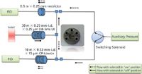
Figure 1: Analytical multidimensional gas chromatography (MDGC) system configuration with a five-port planar microfluidic device as a Deans switch.
The sample was introduced into the GC instrument with a 7683B automated liquid sampler (Agilent Technologies) equipped with a 10 μL liquid syringe. The carrier gas was helium. The inlet was a split– splitless inlet in split mode with a 4 mm ultra-inert liner (Agilent Technologies) at a split ratio of 20:1. The inlet temperature was 250 °C. The inlet pressure programme was 21.9 psig (5.5 min) to 5 psig at 99 psig min and maintained at 2 psig for 15 min. The auxiliary pressure programme for Deans switching was 4.6 psig (5.5 min) to 10 psig at 99 psig min and maintained at 10 psig for 15 min. The flame ionization detector temperature was 250 °C, with hydrogen flow at 35 mL min, air flow at 350 mL min and nitrogen flow at 25 mL min.
The temperature was programmed from 40 °C (2 min) to 250 °C at 15 °C min (5 min). The sample size was 1 μL. The column used in the first dimension was a 30 m × 0.25 mm, 0.25 μm DB-5ms UI column (Agilent Technologies). The column used in the second dimension was a 10 m × 0.53-mm, 15 μm CP-Lowox column (Agilent Technologies). The restrictor used for flow balancing was a 0.5 m × 0.25-mm i.d. uncoated but deactivated fused silica column (Agilent Technologies). Data were collected with ChemStation software B.01.03 (Agilent Technologies).
Carrier and utility gases such as helium, nitrogen, hydrogen and air used for system performance studies were acquired from Air Liquide. Trichloroethylene, tetrachloroethylene and solvents used for syringe cleaning and dilution, such as methanol and hexane, were acquired from Sigma-Aldrich. Commercial marine gas oil grade A used for method development was obtained from a local marine fuel depot in Victoria, Canada.
Results and Discussion
MDGC was used to address the separation problems described earlier. Unlike in single dimensional GC, MDGC separation of analytes is derived from the difference in selectivity of the columns used in the first and second dimension.
In the past, implementing MDGC has been a rather difficult task for practitioners because of the interface used and connections used (7–9). Chromatographic problems, such as leaks resulting from the difference in thermal expansion and large void volume, were difficult to ameliorate. The advent of planar microfluidic devices significantly improved the performance and ease of implementation of MDGC (10,11). As part of the flow architecture, embedded fluid logic gates help to prevent mixing or back diffusion of a gas against a flow stream. Planar microfluidic platforms have low internal volumes with minimal diffusion and low thermal mass and as such are suitable for use with contemporary capillary GC applications. A connection with external tubing is made directly where threaded bosses are also incorporated into the fused wafer. Leak-free and low dead volume connections were attained by the use of finger-tight metal ferrules (12).
A five-port device was selected for use as a Deans switch and as a platform for the implementation of MDGC in this analytical configuration (13–15). The manipulation of column flows was at first attempted by using a three-port 5 W, 24V DC fluid automation system valve. No sooner as the valve was installed, spurious chromatographic contaminants were detected by the system in the second dimension on the column, especially when the system was allowed to idle over a prolonged period of time. When the valve is energized, higher levels of contaminants were encountered. The out-gassed volatile materials were retained by the column because of its high retention characteristics for volatile and semi-volatile compounds, and are eluted as discrete peaks when temperature programming is applied, causing unreliable results. This contamination issue was successfully resolved by replacing the FAS valve with a new type of valve described earlier in the experimental section.
A 30 m × 0.25 mm, 0.25 μm column was used in the first dimension to perform tasks such as pre-separation of the target compounds from the matrix, quarantining potential contaminants and backflushing the heavier hydrocarbons of the matrix to vent. The stationary phase used in this column, 5% phenyl dimethylsiloxane, has been proven to be rugged, inert and able to withstand multiple thermal cycles without losing column efficiency. In addition, the column can tolerate a moderate level of impurities in carrier gas, such as ppm level water, carbon dioxide and air. As a result, the technique can be deployed in remote laboratories or marine terminals. Under the conditions used the column has virtually no retention for light components of up to nC6, but it yields respectable retention for heavier hydrocarbons and aromatics from the fuel matrix, with carbon numbers ranging from nC10 to nC26. If present, trichloroethylene and tetrachloroethylene co-elute perfectly with the other components in the fuel matrix in the first 5.5 min of the analysis, and at an eluting temperature less than 100 °C. If a co-elution has to take place, having it at the lowest oven temperature is advantageous to maximize the separation power of the column used in the second dimension as the critical pair is being "cut" to the second dimension. Once the cuts are executed, with a lower eluting temperature of the critical pairs, backflushing of sample matrix can be initiated earlier, therefore improving overall sample throughput and system cleanliness. The design of this specific Deans switch approach involves having both columns in the same oven.
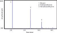
Figure 2: Chromatogram of 50 ppmw of trichloroethylene and 25 ppmw of tetrachloroethylene in hexane on the second dimension (analytical) column.
For the second dimension (analytical column), a 10 m × 0.53 mm, 15 μm column was used. Unlike the column used in the first dimension which is a classic wall-coated open tubular column where separation of analytes is mainly based on partition chromatography, this column is a porous layer open tubular column which uses ionic sorbent as a stationary phase with the main separation mechanism based on adsorption chromatography. The column was originally designed to deliver high selectivity for low oxygenated compounds, hence the name "low-ox" (16,17). We discovered that the low-ox column has useful selectivity for the separation of chlorinated compounds against hydrocarbons and aromatics. The high selectivity is derived from the strong interaction of the halogens with the ionic sorbent medium. By leveraging the difference in separation mechanisms and selectivities, trichloroethylene and tetrachloroethylene can be separated well. Figure 2 shows a chromatogram of 50 ppmw of trichloroethylene and 25 ppmw of tetrachloroethylene in hexane "cut" to the second dimension (analytical) column.
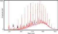
Figure 3: Overlay of chromatograms of a gas oil sample and the same sample spiked with 5 ppmw of trichloroethylene and 2.5 ppmw of tetrachloroethylene on the first dimension column.
An overlay of chromatograms of a gas oil sample and the same sample spiked with 5 ppmw of trichloroethylene and 2.5 ppmw tetrachloroethylene on the first dimension column is shown in Figure 3. As can be seen, the two target compounds co-eluted perfectly with other fuel matrix components at retention times of 3.5 min and 5.4 min, respectively. In contrast, Figure 4 shows an overlay chromatogram of a gas oil sample and the same sample spiked with 5 ppmw of trichloroethylene and 2.5 ppmw of tetrachloroethylene with the two compounds "cut" to the second dimension. Unlike in the first dimension, here on the second dimension, the analytes were nicely separated from the matrix interferences that exist in the "cut" windows; namely from 3.45 min to 3.55 min, and 5.35 min to 5.45 min.
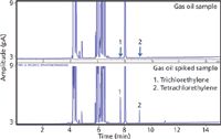
Figure 4: Overlay of chromatograms of a gas oil sample and the same sample spiked with 5 ppmw of trichloroethylene and 2.5 ppmw of tetrachloroethylene on the second dimension (analytical) column.
From an operational stand-point, after the transfer of the analytes of interest from the effluent of the coarse separation column (first dimension) onto the analytical column (second dimension), taking advantage of the extra pressure source available with the Deans switch raises the extra pressure to 10 psig while the inlet pressure is lowered to 2 psig. This means that any impurities trapped on the first dimension column will be removed from the column via backflush. Figure 5 shows an overlay of chromatograms of marine gas oil spiked with 5 ppmw of trichloroethylene and 2.5 ppmw tetrachloroethylene with backflush used after the second cut at 5.5 min. As shown in the chromatogram, immediately after backflush is initiated, the detector signal becomes a flat line indicating that instead of flowing towards the detector, the sample matrix is now being backflushed via the inlet vent. Backflushing speeds up analysis time by at least 30% in this application and lowers the oven temperature required to remove the contaminants from the analytical system (18,19).
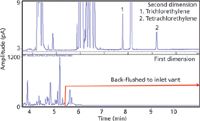
Figure 5: Overlay of chromatograms of a gas oil sample spiked with 5 ppmw of trichloroethylene and 2.5 ppmw of tetrachloroethylene with backflush engaged after the second cut at 5.5 min.
Figure 6 shows a chromatogram of a gas oil sample known to have been contaminated with chlorinated hydrocarbons waste. Trichloroethylene and tetrachloroethylene were identified by retention and their concentrations in the sample were quantified to be 1.3 ppmw and 7.6 ppmw, respectively. This clearly demonstrates the utility of the technique developed.

Figure 6: Chromatogram of a gas oil sample known to have been contaminated with trichloroethylene (1.3 ppmw) and tetrachloroethylene.
Repeatability of retention times for all compounds was found to be less than 0.05% (n = 20). Repeatability of area counts at two levels, namely 10 ppmv and 100 ppmv, over a period of two days was found to be less than 3% (n = 10). Detection limits of less than 250 part-per-billion (ppb) were established. Compounds of interest were found to be linear over a range of 500 ppbv to 500 ppmv, with correlation coefficients greater. A complete analysis of the two targeted chlorinated compounds in marine gas oil can be conducted expediently in less than 15 min.
It was found that the technique was rugged with a high degree of reliability and was suitable for deployment in remote laboratories or marine terminals for screening marine fuels such as gas oil for targeted contaminants like trichloroethylene and tetrachloroethylene. The procedure is flexible and can be reconfigured to target other organic contaminants of interest in marine fuels if required.
Conclusions
A practical and reliable analytical procedure that incorporates MDGC with a planar microfluidic device as a Deans switch was successfully developed for the characterization of chlorinated degreasers, such as trichloroethylene and tetrachloroethylene, in marine distillate fuel or gas oil. By leveraging the enhanced selectivity obtained from columns with different selectivities and separation mechanisms, the targeted compounds can be accurately identified and quantitated without the requirement of a mass spectrometer, and with a low possibility for misidentification.
The successful implementation of this technique allows a complete sample analysis in less than 15 min. With the extra pressure source available, heavier components in the fuel matrix can be backflushed to vent, and, as a result, sample throughput can be improved by at least 30% as well as overall system reliability and cleanliness enhanced.
Acknowledgements
Dr Kayte Parlevliet, Dr Peter Dawes and Dr Dan Difeo of SGE Analytical Science are acknowledged for providing the five-port planar microfluidics device for testing and evaluation. Dave Walter, Dan Martin, Vicki Carter, Dr Taylor Hayward and Andy Szigety of Dow Chemical are acknowledged for their support. Robert Shellie is the recipient of an Australian Research Council Australian Research Fellowship (project number DP110104923).
Ronda Gras is an associate analytical manager of the Dow Chemical Company, Alberta, Canada.
Hernan J. Cortes, PhD, is Principal of Hernan J. Cortes Consulting, LLC., providing services in process and analytical chemistry, and in the development and implementation of advanced separation science methodology. He is also Adjunct Professor in Chemistry at the University of Tasmania, Hobart, Australia.
Jim Luong is a senior technology associate of the Dow Chemical Company, Alberta, Canada.
"Coupling Matters" editor Robert Shellie has extensive experience in hyphenated techniques and is currently an ARC Australian Research Fellow at the Australian Centre for Research on Separation Science (ACROSS) at the University of Tasmania, Hobart, Australia. He is also a member ot LCGC Europe's editorial board. Direct correspondence about this column should go to LCGC Europe editor-in-chief, Alasdair Matheson, 4A Bridgegate Pavilion, Chester Business Park, Wrexham Road, Chester, CH4 9QH, UK, or e-mail amatheson@advanstar.com
References
(1) International Organization for Standardization, Method ISO-8271: 2012, Petroleum Products — Specifications for Marine Fuels, Geneva, Switzerland.
(2) American Society for Testing Materials, Standard Specification for Marine Fuels, Method D-2069-91, West Conshohocken, Pennsylvania, USA.
(3) A. Horvath, Halogenated Hydrocarbons, (Marcel Dekker, Inc., New York, USA, 1982).
(4) NIOSH Manual of Analytical Methods, 3rd ed., V. 2, NMAM 1022. U.S. Department of Health and Human Services, Publ. (NIOSH) 84-100 (1984).
(5) NIOSH Current Intelligence Bulletin 2, Trichloroethylene, NIOSH (June 6, 1975), U.S.Department of Health, Education, and Welfare, Publ. (NIOSH) 78–127 (1979).
(6) USEPA, In-Use Marine Diesel Fuel, Engine Programs and Compliance Division, EPA document 420-R-99-027 (August 1999).
(7) P. Knauss and R. Freeman, J. High Resolut. Chromatogr. 5(10), 546–552 (1982).
(8) G. Johnson, A. Tipler and D. Crowshaw, J. High Resolut. Chromatogr. 13(2), 130–136 (1990).
(9) P. Apps, J. Sep. Sci. 29(15), 2338–2349 (2006).
(10) P. Dawes, B. Barnett and R. Hibbert, "Proceedings of the 34th International Symposium on Capillary Chromatography", Poster(Riva Del Garda, 2010), P. Sandra, Ed.; Kortrijk, 2010.
(11) R. Freeman, P. Dawes, B. Barnett and R. Hillbert, "Proceedings of the 35th International Symposium on Capillary Chromatography", Poster, San Diego, 2011, CASSS: San Diego, 2011.
(12) J. Luong, R. Gras, R.A. Shellie and H. Cortes, J. Sep. Sci. 36(1), 182–191 (2013)
(13) J. V. Seeley, J. Chromatogr. A 1255, 24–37 (2012).
(14) W. Bertsch, HRC J. High Resolut. Chromatogr. 22(12), 647–665 (1999).
(15) W. Bertsch, HRC J. High Resolut. Chromatogr. 23(3), 167–181 (2000).
(16) J. de Zeeuw and J. Luong, Trends Anal. Chem. 21(9–10), 594–607 (2002).
(17) V.G. Berezkin and J. de Zeeuw, Capillary Gas Adsorption Chromatography, (Huthig, Heidelberg, Germany,1996).
(18) J. Luong, R. Gras, H. J. Cortes and R.A. Shellie, J. Chromatogr. A. 1271, 185–191 (2013).
(19) J. Luong, R. Gras, R. Mustacich and H. Cortes, J. Chromatogr. Sci. 44(5), 253–261 (2006).

New Study Reviews Chromatography Methods for Flavonoid Analysis
April 21st 2025Flavonoids are widely used metabolites that carry out various functions in different industries, such as food and cosmetics. Detecting, separating, and quantifying them in fruit species can be a complicated process.
University of Rouen-Normandy Scientists Explore Eco-Friendly Sampling Approach for GC-HRMS
April 17th 2025Root exudates—substances secreted by living plant roots—are challenging to sample, as they are typically extracted using artificial devices and can vary widely in both quantity and composition across plant species.
Sorbonne Researchers Develop Miniaturized GC Detector for VOC Analysis
April 16th 2025A team of scientists from the Paris university developed and optimized MAVERIC, a miniaturized and autonomous gas chromatography (GC) system coupled to a nano-gravimetric detector (NGD) based on a NEMS (nano-electromechanical-system) resonator.

.png&w=3840&q=75)

.png&w=3840&q=75)


.png&w=3840&q=75)


.png&w=3840&q=75)


