Molecular Interaction Sensors: A New Type of Detector for Separation Methods
LCGC Europe
Potentiometry is a new detection method for liquid chromatography (LC) and capillary electrophoresis (CE). The principle behind this method is familiar to chromatographers because the signals depend on the partitioning tendency of analytes over the sensor coating and the eluent. This partitioning provokes a change in the surface potential and the detection of these changes can be classified as "potentiometric". A conversion algorithm is needed to convert the generated signals to concentration-related tracings (chromatograms).
Luc J. Nagels,1* Joseph Everaert,1 Bert Vissers,1 Justyna Sekula,1 Hugo Bohets,5 Maria Mongé,2 Karl Peeters,3 Nico Vervoort,3 Kamilla Sadowska,4 Dominika Koziowska,4 Marcus Brewster3 and Koen Vanhoutte,3
1 Chemistry Department, University of Antwerp, Belgium,
2 University of Buenos Aires, Argentina,
3 Johnson & Johnson Pharmaceutical Research & Development, Beerse, Belgium,
4 Department of Chemical Technology, Gdansk University of Technology, Poland,
5 Octens, Edegem, Belgium.
Although high performance liquid chromatography (HPLC) is the method of choice in many analytical laboratories, the limited number of detector types available is still a drawback. According to a review by Rao et al.,1 53% of analyses to determine impurities in pharmaceutical drugs are performed with HPLC, 18% with capillary electrophoresis (CE), and 8% with liquid chromatography mass spectrometry (LC–MS). Ultraviolet (UV) detection was used in 94% of all HPLC instances. The remainder comprised 2% for evaporative light scattering detection (ELSD); 2% for amperometric detection (AD); 1% for fluorescence detection (FD); and 1%, for the combination of conductivity detection (CD) and refractive index detection (RID). Spectroscopy (UV) and mass spectrometry (MS) rapidly developed methods by the coupling with separation science (LC–UV and LC–MS). This rapid development was also observed for electrochemical detection (ED) methods such as pulsed amperometric detection (PAD) and conductivity detection (CD), which are used in ion chromatography (IC).
The third main electrochemistry domain, potentiometry, has not received much attention in HPLC or in CE. Pioneering attempts to use such a detector in separation science have been undertaken by research groups led by Simon,2 Trojanowicz,3 Haddad,4 Chen5 and Isildak.6 More recently, our group published several papers on the potentiometry–liquid chromatography (LC) and potentiometry–CE combination. Our most recent paper on the coupling of potentiometry with LC analysed oligonucleotides.7 and the CE coupling method analysed basic drugs.8 An overview of the earlier work of our group on potentiometry–LC is described in reference 9. The experimental setup is shown schematically in Figure 1.
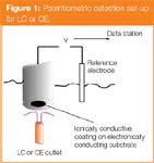
Figure 1
This comprises an electrode which is placed in a large volume wall-jet configuration. The outlet of the LC or CE tubing is placed at short distance (e.g., 100 μm in a classical LC system running at 1 mL/min). The electrode diameter varies from 3 mm (classical LC) to 100 μm (CE). The ionic part comprises a reference electrode, the working electrode and the medium between both. The electronic part contains a high-impedance voltmeter. The potential is monitored by a PC-based data station. More concrete details on the detector construction and on the electrode materials actually used can be found in the literature.10
Unlike redox electrodes, ion selective electrodes (ISEs) do not use chemical (redox) reactions as an energy source to produce an electrical potential. They are non-Faradaic devices: the analytes are not oxidized or reduced. ISE sensors use either a concentration difference of the analyte over an ionically conducting permselective membrane as a drive for potential (electrical energy) generation, or the tendency of the analyte ion to distribute itself between the sample and the membrane surface or membrane interior. In the latter ISE system, a change in the Donnan (Donnan–Nernst, Zeta) surface potential occurs at the membrane/analyte solution surface. Figure 2 illustrates this type of system.
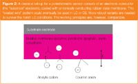
Figure 2
The distribution (partition or transfer) tendency of the analyte ion (a cation in the example in Figure 2) between sample and membrane surface, ΔGtr, is converted into an electrical energy term (-q.ΔE). This is only possible if the counterion is excluded from the membrane (we have a "permselective" membrane). In this instance, the analyte ion adsorbs or partitions or ion-exchanges with the membrane (mark the similarity to, for example, LC). In LC conditions, this process will occur only at the membrane surface. Analyte ion and counterion are separated locally. An ionic capacitor is formed, and a potential (E) — the signal, measure in millivolts (mVs) — is created. For readers with a desire to follow the evolution of ideas in potentiometry, an article by Buck and Lindner11 is a good starting point.
Many ideas are scattered throughout the literature, dealing with the distribution mechanism and we, therefore, describe a simplified model. This is also the situation in chromatography and it is very difficult to predict precisely why an analyte will distribute itself over a liquid phase and a stationary phase. In the lab, and in nature, surface potentials are created, destroyed and changed by non-Faradaic processes. Ions are deplaced by molecular interactions (enthalpy), or by entropic driving forces, which changes local potentials (Figure 2). No chemical reactions are occurring. Molecular interactions (an enthalpy contribution) may be important, but entropy factors also play an important role.
A classical composition of the rubber coating could be one-third of polyvinyl chloride (PVC), two-thirds of a plasticizer, such as dioctyl sebacate (DOS), and a few percentages of a large lipophilic anion such as p-chloro tetraphenyl borate (pClTPB). A small mobile countercation, such as Na+ , completes the picture. Eventually, one could add a receptor molecule, showing a high affinity for the analyte cation. The latter is mostly called an "ionophore" in ISE terminology. The membrane is a cation exchanger with large and immobile lipophilic anionic sites, and mobile (exchangeable) cationic charges. It is comparable with ion exchange materials with fixed anionic groups and exchangeable cations, used in LC. The "drive of the analyte ion to distributed itself." can be expressed quantitatively, by considering the Gibbs free energy change which is associated with the transfer of an analyte ion from the eluent phase into the membrane phase:


Equation 1 is obtained using Haber–Born cycle types of reasoning. Equation 1 states that the Gibbs free energy needed to transfer an analyte ion from the eluent phase into the membrane phase (ΔGtr) is equal to the Gibbs free energy to transport an analyte ion from the eluent phase to vacuum (–ΔGdissolution in eluent), plus the Gibbs free energy to transport the same analyte ion from vacuum to the membrane
(+ΔGdissolution in membrane). In Equation 2, the membrane dissolution term is split-up in three terms, associated respectively with the membrane components, such as polymer and plasticizer (ΔGsolv), with the lipophilic anion (ΔGion) and with a receptor molecule (ΔGcomplex). Equation 2 allows us to discuss relative responses of organic analyte ions towards the detector, in a qualitative manner. Finally, ΔGtr is related to the change in potential, which will form the detector's signal:
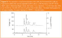
Figure 3
As stated in Equation 3, ΔGtr will depend on molecular interactions and on entropic factors. It is known, for example, that for the distribution of a basic drug or a steroid hormone over a water phase and a membrane phase, the entropic factor (–TΔS) is often, at least, of the same order of magnitude as the ΔH factor. Equation 2 could also be applied to the distribution (retention) of analytes in an HPLC system. Chromatography experts often divide chromatographic systems into "partition", "ion-exchange", "adsorption" systems,12 corresponding to systems with a high contribution of, ΔGsolv (solvatation by the stationary phase), ΔGion and ΔGcomplex respectively.
Cationic organic substances were injected on a classical reverse phase (RP) column using the setup described in Figures 1–2 as a detector. In Figure 3, we show the separation of four basic drugs, detected with this sensor (lower tracing). We know, however, that the detector's mV output is not linear with concentration, so we will need a conversion from the mV output to a concentration-related output (upper tracing).

So how is the lower tracing (measured in mV) in Figure 3 converted to the upper tracing in Figure 3, which is a concentration-related signal?
In Figure 4, we have measured a typical mV versus logcanalyte (injected concentrations) curve for dapoxetin. The shape of such curves is well known by analytical chemists working with potentiometry. They work in the upper part of the curve, where the signal is linearly dependent on logcanalyte. In that part, we have a Nernstian relationship between the signal and canalyte:

The total curve of Figure 4 is described by a Nicolski–Eisenmann equation (Equation 5) This equation contains the constant "interference" term "Cst ". In chromatographic conditions, the interferences are caused by the eluent components, which can be considered constant during the elution of a particular peak.
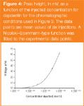
Figure 4
Figure 4 shows the experimentally measured points with standard deviation (σ, n = 6), and a curve which was iteratively fitted by a weighted least squares method to a Nicolski–Eisenmann equation using Excel's "solver". The curve shows a high correlation with the experimental data points, indicating that a Nicolski–Eisenmann function closely describes the experimental calibration curve, even in LC conditions. The fitted function yields the following values (equation 5): E0 = 358 mV, S = 55 mV, Cst = 3 × 10⁻⁷

The chromatographic detection limit (DL), which is determined by the chromatographic peak height equal to 12 × σbaseline noise) for dapoxetin in the conditions of Figure 3 is 10–7 M. This means that, in chromatographic conditions, one can perfectly perform measurements in the non-linear part of the dapoxetin calibration curve, for example, from 10–6 M to 3 × 10⁻⁵ M, at good signal to noise ratios (S/Ns).
In chromatography, we need the transpose of the Nicolski–Eisenmann equation (Equation 5). We can arbitrarily set E = 0 at canalyte = 0. This means that the baseline signal is set to 0 mV. In this condition, the transpose of the Nicolski–Eisenmann equation was derived as described in reference 8:

The transformation of the mV output of the potentiometric detector to10mV/S – 1 closely follows the concentration profile of the eluting components (detailed study to be published).
The sensor coating withstands gradient elution conditions for five active basic compounds (Figure 5). The measured DLs for these substances (peak height equal to 12 × σnoise) were in the low 10–7 M range (injected concentrations). This was 10 times better than for the UV detector at 225 nm. Yet, all these substances are highly UV-absorbing.

Figure 5
The sensitivity of the detector for cationic organic substances was highly related to the lipophilicity of the analyte. LogP is a good indicator in this respect.13 Compounds with logP values higher than 2 are very sensitively detected. Lower logP drugs can also be determined, but less sensitively. The pH of the chromatographic eluent should be lower than the pka of the analyte to keep, for example, basic drugs in their cationic form.
Anionic organic substances are also very well detected. Figure 6 shows a separation of (a) oxalic acid (7.69 × 10⁻³ M injected); (b) malonic acid (1.92 × 10⁻³ M), and (c) maleic acid (3.85 × 10⁻⁴ M).
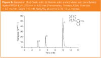
Figure 6
DLs for these acids are also extremely low. For maleic acid, the 12 × σnoise peak heights were obtained for injected concentrations lower than 10–7 M. The electrode membranes used in the example of anionic organic substances contain a large lipophilic cation14 (Figure 7). As these acids are often rather hydrophilic, the ΔGsolv term in Equation 2 is less important. ΔGion and ΔGcomplex become important. Typically, we put a highly charged lipophilic nitrogen macrocycle of the type shown in the insert in Figure 6 in the membrane. It serves as a lipophilic cation, and as an ionophore at the same time. This nitrogen-containing macrocycle with lipophilic tail, can be used for sensitive detection of organic acids. It was one of many "active" compounds, synthesized and tested by the group of Professor Biernat, of the Technical University of Gdansk, and Professor Pietraszkiewicz, of Warsaw University.

Figure 7
The plasticizer was o-NPOE.
Monocarboxylic acids, sulphonic acids and organic phosphate derivatives can also be detected sensitively. The factors governing the detection selectivity are not yet so clear as for cationic organics. In the latter example, we saw that lipophilicity was the determining factor. This is also the situation with certain organic acids: see Figure 7, where we show the determination of linear chain sulphonic acids. The situation is more complex however: heptane sulphonic acid (C7) obviously has a higher logP than hexane sulphonic acid (C6), yet it shows a lower response.
Sodium salts of long-chain aliphatic or aromatic sulphonic acids are used as detergents. The calcium and magnesium ions present in hard water do not form insoluble precipitates with sulphonates as they do with carboxylates. Some sulphonic acid derivatives, for example, the sulpha drugs, are very important as antibiotics.
Sulphates also give good results (Figure 8). This chromatogram gives an analysis of a hair shampoo (upper chromatogram). Lauryl sulphate is clearly present, together with many other anionic detergents. The separation was not yet optimized for anionic detergents, for example, of the laureth sulphate type. It is clear, however, that the detector can be used without an ion suppressor system, as required by a conductivity detector in an IC system. The lower chromatogram gives the detector's response for linear chain aliphatic sulphates. The peak labelled C12 is lauryl sulphate, the starting product for the popular laureth-type detergents.
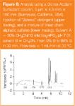
Figure 8
The detector is also very sensitive for cationic detergents. Given the growing industrial importance of synthetic surfactants in thousands of consumer products, the new detection technique is expected to become important in this application area.
The good response to sulphated compounds also makes the detector suitable to determine metabolicbreakdown products (Figure 9). This figure represents the analysis of a urine sample of a 28-year-old male, showing naturally present dehydroepiandrosterone sulfate (DHEAS).
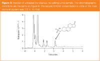
Figure 9
The example of Figure 9 demonstrates the capability of the detector in the area of ionized organics with biomedical or biotechnological importance. It should be noted that large multiply-charged molecules can be determined with much better sensitivity than predicted by the present theories.7
Potentiometric sensors lend themselves to miniaturization. We demonstrated this in a recent article on drugs of abuse.13 Spectroscopic methods are unsuitable for miniaturization because of their dependency on the length of the light pathway. ADs have flow-rate-dependent signals, which is a serious handicap in extremely low flow-rate systems of analysis. The advantage of potentiometric sensors is the enormous concentration range which can be covered. An analyst can determine a compound in a highly concentrated sample, and simultaneously look at the minor impurities present.
Conclusions
Potentiometric sensors can be used as sensitive detectors in separation methods. Special membrane constructions are needed. Conversion of the mV signals to a concentration-related signal is also required to obtain chromatograms or electropherograms. The sensors can be applied in miniaturized systems. Non-UV-absorbing charged organic molecules could be the target analytes for this detector.
Acknowledgments
The authors would like to thank IWT (grant 040399), the FWO Vlaanderen, the European Community (ALFA project) for financial support, and Luc Lammens for organizational support.
Luc Nagels is professor at the chemistry department of the University of Antwerp, Belgium. He firmly believes in new ways of thinking about and new applications for potentiometry. Several people from his laboratory work on this subject, such as DrHugo Bohets (who is currently researcher in spin-off company Octens, a newly established company with the mission to develop potentiometric applications), Joseph Everaert and doc students Bert Vissers and Justyna Sekula. He collaborates with groups from the pharmaceutical industry, including DrMarcus Brewster, Dr Koen Vanhoutte, Dr Nico Vervoort and DrKarl Peeters from Johnson & Johnson. Also organic synthetic groups actively participate in designing new sensor materials, for example the group of professor Jan Biernat, of the Gdansk Uni. of Technol, Poland, and professor Pietraszkiewicz, of Warsaw (Acad. Sci.) were involved, with contributions from visiting Erasmus students Kamilla Sadowska and Dominica Kozlowska. Another visiting researcher, from professor Martin Negri's group in Buenos Aires, DrMaria Eugenia Mongé, also contributed.
Column Editor, Robert Smits, is the president of the Koninklijke Vlaamse Chemische Vereniging (Royal Flemish Chemical Society). He is Chairman of the biennial "International Symposium on Hyphenated Techniques in Chromatography and Hyphenated Chromatographic Analysers" and a member of the Editorial Advisory Board of LCGC Europe.
References
1. R.N. Rao and V. Nagaraju, J. Pharm. Biomed. Anal., 33(3), 335–377 (2003).
2. A. Manz and W. Simon, Anal. Chem., 59(1), 74–79 (1987).
3. M. Trojanowicz and M.E. Meyerhoff, Anal. Chem., 61(7), 787–789 (1989).
4. Z.L. Chen, P.W. Alexander and P.R. Haddad, Anal. Chim. Acta, 338(1–2), 41–49, (1997).
5. Z.L. Chen and P.W. Alexander, Instr. Sci. Technol., 26(4), 421-426, (1998).
6. I. Isildak, Chromatographia, 49(5–6), 338–342 (1999).
7. Y. Bao et al., Analytica Chimica Acta,. 550(1–2), 130–136 (2005).
8. J. Sekula et al., Anal. Chem., 78(11), 3772–3779, (2006).
9. L.J. Nagels, G. Bazylak and D. Zielinska, Electroanalysis, 15(5–6), 533–538 (2003).
10. D. Zielinska et al., Journal of Chromatography A, 915(1–2), 25–33, (2001).
11. R. P. Buck and E. Lindner, Analytical Chemistry, 73(3), 88A–97A, (2001).
12. J. Cazes and R.P.W. Scott (Ed), Chromatography Theory, (Marcel Dekker, New York, 2002).
13. B. Vissers et al., Electrochimica Acta, 51(24), 5062–5069, (2006).
14. D. Zielinska et al., Analytica Chimica Acta, 523(2), 177–184 (2004).

Removing Double-Stranded RNA Impurities Using Chromatography
April 8th 2025Researchers from Agency for Science, Technology and Research in Singapore recently published a review article exploring how chromatography can be used to remove double-stranded RNA impurities during mRNA therapeutics production.
Study Explores Thin-Film Extraction of Biogenic Amines via HPLC-MS/MS
March 27th 2025Scientists from Tabriz University and the University of Tabriz explored cellulose acetate-UiO-66-COOH as an affordable coating sorbent for thin film extraction of biogenic amines from cheese and alcohol-free beverages using HPLC-MS/MS.


