Hollow-Fibre Liquid-Phase Microextraction in the Three-Phase Mode – Practical Considerations
LCGC Europe
Describes practical aspects of hollow-fibre liquid-phase microextraction in the three phase mode (HF3LPME) and also electromembrane extraction (EME).
In this instalment of "Sample Preparation Perspectives," Norwegian authors from the University of Oslo describe the practical aspects of hollow fibre liquid-phase microextraction in the three-phase mode (HF3 LPME). The guest authors highlight important practical issues related to the supported liquid membrane, the hollow fibre and the extraction itself. They also discuss practical work with electromembrane extraction (EME), which is related to HF3 LPME but uses an electrical potential as the driving force for the extraction.
This month's instalment describes practical aspects of hollow-fibre liquidphase microextraction in the three-phase mode (HF3 LPME). HF3 LPME is a microscale sample preparation technique (1) where target analytes are extracted from an aqueous sample through a supported liquid membrane (SLM) that is immobilized in the pores of a porous polymeric material and into a volume of acceptor solution (typically, 10–30 μL). In this context, the porous polymeric material is a hollow fibre. Here, we highlight important practical issues related to the SLM, the hollow fibre and the extraction itself because these issues are important for successful HF3 LPME. We also discuss practical work with electromembrane extraction (EME), which is related to the HF3 LPME device but uses an electrical potential as the driving force for the extraction (2).
How Does HF3LPME Work?
HF3 LPME can be used for extraction of basic or acidic analytes from aqueous samples. Figure 1 illustrates a setup for HF3 LPME. The sample is contained in a sample vial and the pH is adjusted in the sample before extraction to keep the analytes in their uncharged state. For basic analytes, the sample is made alkaline, and for acidic analytes, the sample is acidified. A small piece of a porous hollow fibre, typically made of polypropylene, is closed in one end and dipped in an organic solvent immiscible with water. In a few seconds, this organic solvent is immobilized in the pores in the wall of the hollow fibre by capillary forces, forming an SLM.
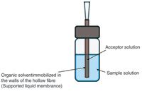
Figure 1: Illustration of a typical hollow-fibre liquid-phase microextraction in the three-phase mode (HF3LPME) setup.
A 10–30 μL volume of aqueous acceptor solution is then injected into the lumen of the hollow fibre. For basic analytes, the acceptor solution is acidic, whereas it is alkaline for acidic analytes. The hollow fibre is finally placed into the sample and the whole assembly (sample vial and hollow fibre) is agitated for typically 15–45 min. During this time, analyte molecules are extracted in their uncharged state from the sample into the SLM, and further into the acceptor solution. In the acceptor solution, the analyte molecules become ionized, which prevents them from re-entering the SLM. After extraction, the acceptor solution is collected and analysed directly by high performance liquid chromatography (HPLC), capillary electrophoresis (CE), mass spectrometry (MS) or other related analytical techniques.
The major advantages of HF3 LPME can be summarized as follows:
- High enrichment (up to 25,000-fold) (3)
- Excellent sample clean-up
- Direct compatibility with HPLC, CE and MS
- Low solvent consumption (10–30 μL of solvent for each extraction).
Advantages, as well as limitations, of HF3 LPME have been discussed substantially in the literature and several reviews discussed a broad range of applications (4–11).
Which Hollow Fibres Are Used for HF3 LPME?
The porous hollow fibres used for HF3 LPME are typically made of polypropylene (4). Most work published in the literature has been accomplished with a polypropylene hollow fibre from Membrana (Wuppertal, Germany) termed "Q3/2" that has an internal diameter of 600 μm, a wall thickness of 200 μm and a pore diameter of 0.2 μm (4). The hollow fibre is connected to a pre-cut pipette tip or a medical syringe needle. The pipette tip or syringe needle serves as a guide tube to facilitate the injection and withdrawal of the acceptor solution, as illustrated in Figure 2. The fibre can be arranged either in the loop configuration with connections in both ends (Figure 2b) or in the rod configuration with a connection in one end and the other end closed (Figure 2a). To close the hollow fibre, mechanical pressure with a pair of pincers can be used — no heat or glue is required. In our laboratory, we use pipette tips for the connections. In this case, we carefully heat the connection between the tip and the fibre with a soldering iron to prevent disruption.
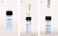
Figure 2: Different configurations for hollow-fibre liquid-phase microextraction in the three-phase mode (HF3LPME): (a) rod configuration, (b) loop configuration and (c) hollow fiber attached directly to the needle of a microsyringe.
Alternatively, the hollow fibre can also be attached directly to the needle of a microsyringe for easy injection and withdrawal of the acceptor solution, as illustrated in Figure 2c (12). Alternative fibre dimensions can also be used, but generally the thickness of the wall of the fibre should not exceed 200–300 μm because the extraction speed and the recovery are dependent on the thickness of the SLM. Fibres with internal diameters less than 600 μm have been reported to speed up HF3 LPME with small volumes of acceptor solution for high enrichment (3), and hollow fibres with internal diameters larger than 600 μm have been used for easier injection and withdrawal of the acceptor solution (13,14).
What Solvents Can Be Used as the SLM?
In HF3 LPME, the SLM is an intermediate extraction medium. Analytes should be extracted rapidly and efficiently into the SLM, but transport out of the SLM and into the acceptor phase should also be efficient to avoid substantial trapping of analytes in the SLM itself. Substantial trapping in the SLM is undesirable because it reduces the extraction recovery. In other words, finding the optimum SLM solvent for the application is an important step.
For HF3 LPME, dihexyl ether and 1-octanol have been the most popular SLM solvents (4). As seen in Table 1, these two solvents have a high boiling point (> 195 °C), and when the hollow fibre is dipped in the solvents, little or almost no evaporation of the SLM is observed during 2 min of air exposure (Table 1). This observation is important because the hollow fibre with the immobilized SLM is normally exposed for a short time (< 2 min) to open air before it is placed in the sample. After the hollow fibre with the SLM is inserted in the sample in a capped vial, evaporation is no longer an issue because the SLM is protected by the aqueous sample and the system is closed. Volatile solvents such as toluene and 1-chloropentane may be difficult to use in HF3 LPME because they evaporate quickly and give an unstable SLM (see Table 1). In general, it is recommended not to use solvents with a boiling point below 190–200 °C for HF3 LPME.
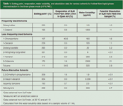
Table 1: Boiling point, evaporation, water solubility, and dissolution data for various solvents for hollow-fibre liquid-phase microextraction in the three-phase mode (HF3LPME).
In addition to the volatility of the solvent, the water solubility is also important. For dihexyl ether, the water solubility is low (< 110 μg/mL), therefore, SLMs made from this solvent are very stable during extraction. With 1-octanol, the water solubility is higher (1200 μg/mL) and this solvent may leak into the sample (and the acceptor solution) in significant amounts. As seen in Table 1, about 11% of a 1-octanol SLM may theoretically leak into 1 mL of sample based on the water solubility, resulting in a significant reduction of the SLM. This level of SLM leakage has been verified experimentally in our laboratory by analysing the sample solution after HF3 LPME with gas chromatography–mass spectrometry (GC–MS) to determine traces of 1-octanol. This loss may be even greater if the sample volume is increased or if surfactants and other emulsifying agents are present in the sample. In general, it is preferred not to use solvents exceeding 200–400 μg/mL in terms of water solubility. In addition to dihexyl ether, solvents such as 1-decanol, dodecyl acetate, 2-nitrophenyl octyl ether and 1-nonanol fulfill the criteria discussed above and have been used in HF3 LPME studies (Table 1) (4). Some new solvents that have also been tested recently in our laboratory for HF3 LPME are included in Table 1 and may be interesting SLM candidates for the future.
How Much Does the SLM Affect the Extraction?
Table 2 (basic drugs as model analytes) and Table 3 (acidic drugs as model analytes) illustrate recent examples from our laboratory in which the extraction recovery in HF3 LPME was strongly affected by the type of solvent used in the SLM. For the basic model analytes, the highest recoveries were obtained with dodecyl acetate, 2-octanone and isopentyl benzene as the SLM solvent. For the acidic drugs, dodecyl acetate, isopentyl benzene and 1-decanol were the top three SLM solvent candidates. A closer look at the results in Tables 2 and 3 indicate several important aspects. First, recoveries were generally higher for the acidic model analytes than for the basic model analytes. The reason for this result was probably that the selected acidic model analytes were slightly more polar than the basic ones. From earlier experience (15), it is well known that extraction recoveries in HF3 LPME are highest for analytes with log P values in the 2–4 range, whereas the extractability decreases somewhat for analytes with log P values exceeding 4.
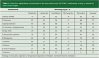
Table 2: Hollow-fibre liquid-phase microextraction in the three-phase mode (HF3LPME) performance ranking of solvents for basic model analytes.
The basic model analytes in Table 2 where highly hydrophobic (log P in the 3.1–5.3 range), and extraction from the organic SLM and into the aqueous acceptor phase was somewhat limited by partition. Because of this, selection of the solvent was very important for the basic model analytes. Second, the extraction performance of each of the solvents was checked against the Snyder solvent selectivity classification system (16). The two top solvents, namely dodecyl acetate and 2-octanone, were both class VI solvents (aliphatic ketones and esters) and the next two solvents were both class VII solvents (aromatic hydrocarbons). Although relatively different in terms of chemical structure, class VI and VII solvents are close to each other in terms of solvent selectivity properties with relatively strong proton acceptor and dipole characteristics.
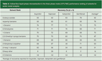
Table 3: Hollow-fibre liquid-phase microextraction in the three-phase mode (HF3LPME) performance ranking of solvents for acidic model analytes.
A somewhat different picture was observed for the acidic model analytes in Table 3. Because these analytes were less hydrophobic, with log P values in the 2.9–4.3 range, they were more easily extracted from the organic SLM and into the aqueous acceptor phase. Therefore, the selectivity of the solvent was less critical for these analytes. Thus, the five top solvents, all of which provided average recoveries of 70% or more, belonged to Snyder classes I, II, VI and VII. These solvents have substantial differences in terms of solvent selectivity, proton acceptor, proton donor and dipole characteristics.
In general, solvent selection in HF3 LPME has been performed mainly by trial and error, testing a limited number of candidates including dihexyl ether and 1-octanol. Most likely, more systematic approaches will be developed in the future that will take further solvent properties into consideration. It also should be mentioned that HF3 LPME is best suited for analytes with log P > 2. For analytes with log P < 2, extraction is more challenging and requires the addition of a carrier such as an ion-pair reagent either to the sample or the SLM (15).
How Should the Dry Hollow Fibre Be Handled?
The dry hollow fibres for HF3 LPME typically are purchased as bundles from the manufacturer. No hollow fibres are currently manufactured specifically for HF3 LPME; instead they are industrial products for totally different applications. We recommend storing the hollow fibres in a closed bag protected from light, because air and light exposure over long time periods might degrade the mechanical stability of the hollow fibre and make it more fragile. Before use, the hollow fibre needs to be cut to form pieces of appropriate length. We recommend using gloves when cutting the fibre to avoid contaminating it. It is important that each piece be cut to exactly the same length. If fibres are of different lengths, the volume of the SLM will vary from extraction to extraction, and this may give some variation in the results. In two-phase hollowfibre liquid-phase microextraction it is common to wash the hollow fibre with acetone before extraction to remove additives in the polymeric material (17). This is less important in HF3 LPME because the acceptor solution is aqueous and most polymer additives are not soluble in aqueous solution. However, for extraction of very hydrophobic analytes, recoveries may be slightly improved if the hollow fibre is prewashed with acetone (18). Each piece of hollow fibre is for single use and should always be discarded after extraction to avoid carryover from one extraction to another.
How Should the SLM Be Prepared?
The SLM normally is prepared by dipping the hollow fibre into the organic solvent for 5–10 s. The organic solvent is immediately immobilized in the pores in the wall of the hollow fibre by capillary forces. This procedure is very simple, but the exact amount of organic solvent is unknown, and excess organic solvent may be located on the surface of the hollow fibre. In such cases, it is recommended to remove excess solvent from the hollow fibre. This can be accomplished either by wiping the fibre with a medical wipe or exposing the fibre and the SLM to ultrasonification in a water bath for 5–10 s. The former method (medical wipe) is recommended, as this procedure has been reported to yield the most reproducible SLM (18).
Alternatively, the organic solvent can be injected into the lumen of the hollow fibre using a microsyringe. In this procedure, the SLM is coated from the inside of the hollow fibre. The advantage here is that the volume of the SLM solvent is controlled more exactly; this approach may be interesting for future automation of HF3 LPME. The typical volume of the SLM solvent in one piece of hollow fibre is 10–30 μL.
It is recommended to immobilize the SLM solvent in the hollow fibre in the shortest amount of time possible before the extraction. This is done to avoid partial evaporation of the SLM solvent and so that the SLM solvent is not gradually swelled into the polymer itself. With solvents like dihexyl ether and 1-octanol, swelling may totally interrupt the SLM after a few days of storage. Other solvents have been found to be as highly stable as the SLM solvent, and they may be immobilized for up to 60 days before use. These solvents include silicone oil AR 20 (polyphenylmethylsiloxane), 2-nitrophenyl octyl ether and dodecyl acetate (18).
How Should the Acceptor Solution Be Loaded?
When the SLM is prepared, the acceptor solution has to be injected into the lumen of the hollow fibre. This is accomplished with a microsyringe. Loading exact and constant volumes of acceptor solution from extraction to extraction is important to obtain the highest repeatability. Make sure that injection of the acceptor solution is performed slowly. Rapid injection of the acceptor solution into the narrow hollow fibre may cause air bubbles, which results in small segments of the hollow fibre containing no active acceptor solution. Air bubbles in the hollow fibre from rapid injection can affect the results significantly and sacrifice repeatability (18).
How Should the Actual Extraction Be Performed?
Extraction is initiated at the time when the hollow fibre, containing both the SLM and the acceptor solution, is placed in the sample. Exact timing of the extraction is important, and the time for each extraction should be measured from the point when the fibre is placed in the sample. Immediately, the whole assembly (sample plus the hollow fibre) should be transferred to an agitator. Agitation (or stirring) is important to facilitate extraction and constantly replenish the sample in close contact with the SLM. Normally, we recommend agitating the entire extraction unit (sample vial and hollow fibre) at 800–1200 rpm, but stirring with small magnetic stir bars may also be used. Normally, HF3 LPME is accomplished at room temperature with no external temperature control.
How Should the Extraction Be Finished?
When the extraction has been completed at an exact stop time, the hollow fibre should be removed immediately from the sample to stop the extraction. This is especially important if extractions are not performed to equilibrium as shown in Figure 3. Additionally, the acceptor solution should be removed immediately from the hollow fibre to avoid partial backextraction into the SLM and loss of analyte.
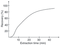
Figure 3: Recovery versus extraction time for haloperidol. Supported liquid membrane: 2-nitrophenyl octylether; sample: 1 mL of 25 mM ammonia buffer pH 10 containing 1 μg/mL haloperidol; acceptor solution: 25 μL of 10 mM HCl.
The acceptor solution is normally removed with a microsyringe and transferred to a sample vial for the final analysis by HPLC or CE. Because the acceptor solution volumes typically used are low, the acceptor solution should be protected from evaporation. Therefore, storage at low temperature in a closed vial is highly recommended. When the acceptor solution is removed from the hollow fibre, it is also important to check the volume of the acceptor phase. Occasionally, the volume collected after extraction is different compared to what was injected into the hollow fibre before extraction; this volume difference is a clear indication of leakage in the system. In such cases, the acceptor solution should be discarded.
What About pH Effects?
In HF3 LPME of basic and acidic compounds, the pH of the sample and the acceptor solution is highly important. For basic analytes, the pH of the sample should be high to suppress ionization of the basic substances and promote their extraction into the SLM, whereas the pH of the acceptor solution should be low to ionize the basic substances upon arrival in the acceptor solution. The latter effect also prevents the analytes from re-entering the SLM. The strong pH-gradients across the SLM serve as the driving force for the extraction. For basic analytes, we normally recommend adjusting the pH 1–3 units above the pKa values of the analytes in the sample and 1–3 units below their pKa values in the acceptor solution. Typically, the sample is made alkaline with sodium hydroxide, whereas hydrochloric acid (10 mM) or formic acid (LC–MS friendly) is used as the acceptor solution (4). For acidic substances, the pH gradient is reversed, with acidic conditions in the sample and alkaline conditions in the acceptor solution. Usually, hydrochloric acid is used to acidify the sample, whereas 10 mM sodium hydroxide or ammonia solution (LC–MS friendly) is used as the acceptor solution (4).
What About EME?
Electromembrane extraction (EME) also is an extraction method for basic or acidic analytes from aqueous samples. Figure 4 illustrates the setup of EME. The setup and procedure are very similar to those used for HF3 LPME. In EME, electrodes are inserted into both the sample and the acceptor solution and the electrodes are connected to a DC electrical power supply. An electrical potential of typically 5–100 V is applied over the electrodes, creating an electrical field over the SLM. This electrical field is the principal driving force for extraction in EME. For EME of basic analytes, the anode is located in the sample, whereas the cathode is placed in the acceptor solution.
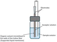
Figure 4: Illustration of a typical electromembrane extraction (EME) setup.
The sample has to be acidified to make sure that the basic analytes are ionized in the sample. Thus, the basic analytes are extracted as protonated species from the sample, through the SLM and into the acceptor solution. The acceptor solution is also acidic to support the electrokinetic transfer and to avoid back-extraction into the SLM. For acidic analytes, the direction of the electrical field is reversed and alkaline conditions are used in the sample and the acceptor solution to maintain the analytes in their charged configuration. The advantages discussed above for HF3 LPME are more or less the same for EME. However, EME is faster than HF3 LPME because the driving force is an electrical potential rather than a pH gradient. EME often can be finished after 5 min. Several reviews have been published summarizing current applications of EME (19–23).
The practical details discussed above for HF3 LPME are also valid, more or less, for EME, but the following differences are important:
- EME is performed with other solvents for SLM compared with HF3 LPME.
- EME is performed with pH conditions different from those used in HF3 LPME.
- The extraction voltage should be selected with care in EME.
The current flowing in the extraction system should be measured in EME.
For EME of basic substances, solvents such as 2-nitrophenyl octyl ether (NPOE), 1-ethyl-2-nitrobenzene and 1-isopropyl-4-nitrobenzene are typically used (2,24–28). For extraction of more polar substances, an ion-pair or another modifier is added to these solvents to facilitate the mass transfer of analytes across the SLM. Typical examples are di-(2ethylhexyl) phosphate (DEHP) and tris-(2-ethylhexyl) phosphate (TEHP) (24,29,30). Acidic compounds have been extracted only a few times by EME and, in those cases, 1-octanol was used as the principal SLM (31,32).
The pH conditions in the sample and in the acceptor solution should be selected to ensure ionization of the analytes and promote their electrokinetic migration across the SLM. Extraction of basic analytes is performed under acidic conditions, typically using dilute hydrochloric acid or formic acid in both the sample and the acceptor solution. However, several basic drugs have been extracted from physiological pH (pH 7.4) solutions when they are still ionized. Acidic analytes are extracted with alkaline conditions in the sample or acceptor solution, typically obtained with dilute sodium hydroxide or ammonia solution.
In EME, the driving force for the extraction is the electrical potential, and this parameter must be optimized. Normally, extraction recoveries increase with increasing voltage up to a certain level until there is no further gain in recovery, as illustrated in Figure 5. The optimal voltage must be established by experimental optimization, as this voltage is dependent on both the analytes and the composition of the SLM. Usually, voltages in the range of 5–100 V are used. During EME, the exact timing of the extraction is important for repeatable data, and we strongly recommend measuring the current flowing in the system. This is accomplished by a microammeter coupled in series with the cable from the power supply. We suggest not operating the system at currents higher than 100 μA because higher currents may cause bubble formation in both the sample and the acceptor solution because of excessive electrolysis.
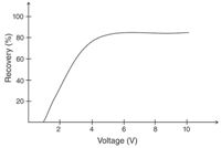
Figure 5: Recovery versus voltage for haloperidol. Supported liquid membrane: 1-isopropyl-4-nitrobenzene; sample: 1 mL of 10 mM HCl containing 1 μg/mL haloperidol; acceptor solution: 25 μL of 10 mM HCl; extraction time: 5 min.
Conclusion
This column instalment focuses on practical considerations regarding HF3 LPME and describes the most important issues for a successful extraction. The first step in the development of a new HF3 LPME application is the choice of the hollow fibre, including the material, size, and configuration. When deciding on the SLM, important factors to consider are the capability of the organic solvent to act as an intermediate extraction medium, the boiling point and the water solubility.
Some new experimental data regarding the leakage of the SLM into the aqueous samples are included in this column instalment; likewise the suggestion of some new organic solvents that are usable in HF3 LPME are mentioned. The practical steps in an HF3 LPME procedure are covered in detail, including the handling of the dry hollow fibre, preparation of the SLM, loading of the acceptor solution, convection of the sample during the extraction and finishing the extraction procedure. The importance of correct pH in the sample solution and in the acceptor solution is discussed. The central issues mentioned also are highly relevant in the procedure of EME, which has been introduced as a faster alternative to HF3 LPME.
Interest in HF3 LPME has been growing for the last decade, although ready-to-use equipment is still not commercially available. We hope that further work in this direction by instrument manufacturers will help HF3 LPME become a viable extraction method. Likewise, automation of the various steps described in this paper will establish HF3 LPME as a useful and robust sample preparation method in the future.
Astrid Gjelstad is a postdoctoral researcher in the School of Pharmacy at the University of Oslo, in Oslo, Norway.
Hamidreza Taherkhani completed his master's thesis in drug analysis in June 2011 at the School of Pharmacy at the University of Oslo, in Oslo, Norway.
Knut Einar Rasmussen is a professor in the school of Pharmacy at the University of Oslo, in Oslo, Norway.
Stig Pederson-Bjergaard is a professor in the School of Pharmacy at the University of Pharmacy at the University of Oslo, in Oslo, Norway.
Ronald E. Majors is the editor of "Sample Preparation Perspectives" and a senior scientist in the Columns and Supplies Division at Agilent Technologies in Wilmington, Delware, USA. He is also a member of LCGC's editorial advisory board. Direct correspondence about this column should go to LCGC Europe editor, Alasdair Matheson, at Advanstar Communications, Bridegegate Pavillion, Chester Business Park, Wrexham Road, Chester CH4 9QH, UK, or e-mail amatheson@advanstar.com
References
(1). S. Pedersen-Bjergaard and K.E. Rasmussen, Anal. Chem. 71, 2650 (1999).
(2). S. Pedersen-Bjergaard and K.E. Rasmussen, J. Chromatogr. A. 1109, 183 (2006).
(3). T.S. Ho, T. Vasskog, T. Anderssen, E. Jensen, K.E. Rasmussen, and S. Pedersen-Bjergaard, Anal. Chim. Act. 592, 1 (2007).
(4). S. Pedersen-Bjergaard and K.E. Rasmussen, J. Chromatogr. A. 1184, 132 (2008).
(5). J.Y. Lee, H.K. Lee, K.E. Rasmussen and S. Pedersen-Bjergaard, Anal. Chim. Act. 624, 253 (2008).
(6). A. Sarafraz-Yazdi and A. Amiri, TrAC-Trends Anal. Chem. 29, 1 (2010).
(7). R. Lucena, M. Cruz-Vera, S. Cárdenas and M. Valcárcel, Bioanal. 1, 135 (2009).
(8). L.M. Zhao, H.K. Lee and R.E. Majors, LCGC N. Amer. 28(8), 580–591 (2010).
(9). H. Kataoka, Anal. Bioanal. Chem. 396, 339 (2010).
(10). L. Arce, L. Nozal, B.M. Simonet, M. Valcárcel and A. Ríos, TrAC-Trends Anal. Chem. 28, 842 (2009).
(11). C. Mahugo-Santana, Z. Sosa-Ferrera, M.E. Torres-Padron and J.J. Santana-Rodriguez, TrAC-Trends Anal. Chem. 30, 731 (2011).
(12). L.Y. Zhu, L. Zhu and H.K. Lee, J. Chromatogr. A. 924, 407 (2001).
(13). A. Bjorhovde, T.G. Halvorsen, K.E. Rasmussen and S. Pedersen-Bjergaard, Anal. Chim. Act. 491, 155 (2003).
(14). G. Ouyang and J. Pawliszyn, Anal. Chem. 78, 5783 (2006).
(15). S. Pedersen-Bjergaard, K.E. Rasmussen, A. Brekke, T.S. Ho and T.G. Halvorsen, J. Sep. Sci. 28, 1195 (2005).
(16). L.R. Snyder, J. Chromatogr. Sci. 16, 223 (1978).
(17). L.M. Zhao and M.K. Lee, Anal. Chem. 74, 2486 (2002).
(18). K.F. Bardstu, T.S. Ho, K.E. Rasmussen, S. Pedersen-Bjergaard and J.A. Jonsson, J. Sep. Sci. 30, 1364 (2007).
(19). S. Pedersen-Bjergaard and K.E. Rasmussen, Anal. Bioanal. Chem. 388, 521 (2007).
(20). A. Gjelstad, LCGC Eur. 23(3), 152 (2010).
(21). P. Kubáň, A. Šlampová and P. Boček, Electrophor. 31, 768 (2010).
(22). A. Gjelstad and S. Pedersen-Bjergaard, Bioanal. 3, 787 (2011).
(23). D.E. Raynie, Anal. Chem. 82, 4911 (2010).
(24). A. Gjelstad, K.E. Rasmussen and S. Pedersen-Bjergaard, J. Chromatogr. A. 1124, 29 (2006).
(25). A. Gjelstad, T.M. Andersen, K.E. Rasmussen and S. Pedersen-Bjergaard, J. Chromatogr. A. 1157, 38 (2007).
(26). I.J.O. Kjelsen, A. Gjelstad, K.E. Rasmussen, and S. Pedersen-Bjergaard, J. Chromatogr. A. 1180, 1 (2008).
(27). A. Gjelstad, K.E. Rasmussen and S. Pedersen-Bjergaard, Anal. Bioanal. Chem. 393, 921 (2009).
(28). L.E.E. Eibak, A. Gjelstad, K.E. Rasmussen and S. Pedersen-Bjergaard, J. Chromatogr. A. 1217, 5050 (2010).
(29). S. Seidi, Y. Yamini, T. Baheri and R. Feizbakhsh, J. Chromatogr. A. 1218, 3958 (2011).
(30). S. Seidi, Y. Yamini, A. Saleh and M. Moradi, J. Sep. Sci. 34, 585 (2011).
(31). M. Balchen, A. Gjelstad, K.E. Rasmussen and S. Pedersen-Bjergaard, J. Chromatogr. A. 1152, 220 (2007).
(32). M.R. Payán, M.Á.B. López, R.F. Torres, M.V. Navarro and M.C. Mochón, Talanta 85, 394 (2011).

Thermodynamic Insights into Organic Solvent Extraction for Chemical Analysis of Medical Devices
April 16th 2025A new study, published by a researcher from Chemical Characterization Solutions in Minnesota, explored a new approach for sample preparation for the chemical characterization of medical devices.
Study Explores Thin-Film Extraction of Biogenic Amines via HPLC-MS/MS
March 27th 2025Scientists from Tabriz University and the University of Tabriz explored cellulose acetate-UiO-66-COOH as an affordable coating sorbent for thin film extraction of biogenic amines from cheese and alcohol-free beverages using HPLC-MS/MS.
Multi-Step Preparative LC–MS Workflow for Peptide Purification
March 21st 2025This article introduces a multi-step preparative purification workflow for synthetic peptides using liquid chromatography–mass spectrometry (LC–MS). The process involves optimizing separation conditions, scaling-up, fractionating, and confirming purity and recovery, using a single LC–MS system. High purity and recovery rates for synthetic peptides such as parathormone (PTH) are achieved. The method allows efficient purification and accurate confirmation of peptide synthesis and is suitable for handling complex preparative purification tasks.


