Field-Flow Fractionation: Virtual Optimization for Versatile Separation Methods
The Column
Flow-field flow fractionation (flow-FFF) offers highly versatile separations for the analysis of complex fluids, covering a size range of macromolecules and particles from 1 nm to 10,000 nm. However, flow-FFF is often perceived as a difficult technique to learn because of the multiple parameters available for adjustment. Recent advances in software for simulating flow-FFF overcome this obstacle, enabling the virtual optimization of flow-FFF methods and opening up the power of flow-FFF separations to non-experts. An added benefit is the ability to easily analyze particle size distributions by elution time from first principles.
Photo Credit: Omelchenko/Shutterstock.com

Stephan Elsenberg1 and Christoph Johann2,1Superon GmbH, Dernbach, Germany, 2Wyatt Technology Europe GmbH, Dernbach, Germany
Flow-field flow fractionation (flow-FFF) offers highly versatile separations for the analysis of complex fluids, covering a size range of macromolecules and particles from 1 nm to 10,000 nm. However, flow-FFF is often perceived as a difficult technique to learn because of the multiple parameters available for adjustment. Recent advances in software for simulating flow-FFF overcome this obstacle, enabling the virtual optimization of flow-FFF methods and opening up the power of flow-FFF separations to non-experts. An added benefit is the ability to easily analyze particle size distributions by elution time from first principles.
Flow-field flow fractionation (flowâFFF) is a proven technique for analytical separations and is used to characterize biopharmaceutical aggregates, drug and gene delivery colloids, polymers, nanomaterials, and others (1–6). Typically used in conjunction with onâline multiâangle light scattering (MALS) (7) and dynamic light scattering (DLS) for the measurement of molar mass and size distributions, in many instances particle sizes can also be calculated directly from elution time according to first-principles FFF theory, which relates channel-flow rate, cross-flow rate, and particle size to elution properties. The resolving power is broadly tunable by simply changing a flow-rate ratio or channel spacer.
Flow-FFF is quite versatile and can provide excellent resolution over a very large size range-from 1 nm to 10,000 nm-with minimal shear and surface interactions. However, it has not seen widespread adoption on the scale of gel permeation chromatography (GPC) or ultracentrifugation. One of the primary obstacles to the extended adoption of flow-FFF is its perception as a complicated technique, with a steep learning curve for method development. The technique’s great versatility is both a blessing and a curse: which initial parameter values should be chosen, and how should they be modified to improve the separation of a given sample?
Flow-FFF is often compared to sizeâexclusion chromatography (SEC). Like flow-FFF, SEC separates molecules and particles according to hydrodynamic size (although the elution order is reversed, making flow-FFF more effective in characterizing aggregates and widely spaced sizes). Given a set of columns, SEC has no adjustable parameters that have any significant impact on resolution: the sample is transported at a constant flow rate under isocratic conditions, with minimal dependence of the separation on flow rate. The column calibration curve, which relates the log molar mass to elution volume, essentially maintains a constant slope between the void and total column volumes, so plate numbers are fixed. Therefore, SEC method development focuses on selecting a mobile phase and column chemistry that achieve purely steric sample–column interactions, and choosing conditions that avoid overloading and degradation.
Conversely, flow-FFF adds multiple degrees of freedom not offered by SEC. There are not one but two flow rates (pertaining to channel flow and cross flow), and two phases of the method with different flow configurations (focus and elution). Variations of these configurations and flow rates, and especially the ratio of channel flow to cross flow, have real impact on separation power, turning retention and resolution into flexible parameters that can be adjusted over the course of a method by defining a variableâflow program. Because of the userâspecified variability in separation properties, plate numbers are not meaningful in characterizing the quality of a flow-FFF setup. Rather, the proof is in the final result for each sample.
A flow-FFF method specification consists of:
- Channel geometry: Channel length and spacer height is selected from four available channel lengths and 4–7 different spacer heights;
- Channel-flow rate, which is usually constant during the method for simplicity, and is also the flow rate to the detector(s);
- A time-dependent cross-flow profile, which produces programmable retention versus particle size during the separation process.
Traditionally, optimization of these parameters has been conducted strictly on a trial-and-error basis bolstered by user expertise and experience. In this article, flowâFFF method development is simplified and accelerated with the help of algorithms and flow-FFF simulation software. With input from one or two physical experiments, the software optimizes the method parameters and simultaneously determines size distributions according to flow-FFF theory. Alternatively, the software can make use of calibration standards similar to SEC to add accuracy to the calculations.
First, we present the workflow for algorithm-based flow-FFF method optimization, quickly achieving baseline separation of a trimodal distribution of monodisperse spherical polystyrene particles in aqueous carrier solution. The second example pertains to real applications from the polymer world-a styrene-butadiene rubber in an organic mobile phase.
Materials and Methods
Experiments were performed on a flow-FFF setup comprising an Eclipse AF4 FFF controller system with an Eclipse Long Channel separation channel (Wyatt Technology) and an Agilent 1260 series HPLC degasser, pump, autosampler, and UV detector (Agilent). The channel incorporated a regenerated cellulose membrane with 5 kDa cutoff (Wyatt Technology). SCOUT DPS software (Wyatt Technology) was used to perform flowâFFF simulations, method optimization, and size distribution calculations. Voyager CDS software (Wyatt Technology) controlled the HPLC system and FFF system, interacting directly with SCOUT DPS to exchange methods and data. Polystyrene latex spheres with nominal radii of 10 nm, 25 nm, and 50 nm were mixed and dispersed in water for the first example (Thermo Scientific). Styrene-butadiene rubber was dissolved in tetrahydrofuran (THF) for the second example, injecting 100 µL at a concentration of 1.723 mg/mL. In all instances, the channel temperature was 25 °C.
General Workflow: Polystyrene Latex Spheres
The workflow of software-based method development usually begins by simulating fractograms (the flow-FFF equivalent of chromatograms) based on the known or assumed size range of the sample. Virtual experiments may be performed under a series of cross-flow gradients, spacer heights, or channel lengths to find suitable conditions for a first physical experiment. The initial method should result in a virtual experiment showing all sample components eluting within a reasonable time range (usually 30–60 min) with acceptable resolution. Alternatively, if nothing is known about the size of the particles and a simulation cannot be performed, the initial method should consist of a standard method that covers a broad size range; the physical experiment will provide the requisite information on the sample’s actual size distribution to improve and fineâtune the method.
After the first physical experiment is performed-according to the initial method-the resulting fractogram is loaded into the simulation software. The software proceeds to calculate the hydrodynamic radius distribution according to the FFF theory (8,9) using the concentration signal, which may come from a UV absorption, refractive index, or fluorescence detector. These results inform the user of the actual size distribution of the sample, which becomes input for further method refinement. Armed with this additional information, all flow conditions and channel geometry parameters can now be adjusted to enhance the separation performance, using additional virtual runs to test the effect of each parameter.
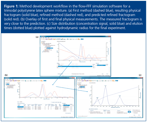
Figure 1(a) shows the initial method (crossâflow profile, dashed blue line) and the resulting fractogram (solid blue line) for the trimodal latex sphere mixture. This method already separates the three particles into well-resolved peaks, although not baseline separated. The actual particle hydrodynamic radii are determined to be 11 nm, 23 nm, and 51 nm, in good agreement with the manufacturer specifications. To achieve a final method with true baseline separation, the run time of the crossâflow gradient was extended (increasing retention of the middle peak), while the cross-flow start value was decreased (reducing retention of the first peak) and the cross-flow end value increased (improving separation between second and third peaks).

Upon modifying the method parameters, the simulated fractogram (Figure 1[a], solid red line) is immediately displayed, making method development fast, easy, and intuitive. In fact, the ability to obtain immediate feedback on the effect of a parameter change and visualize a series of virtual experiments helps to quickly build a user’s intuition and climb the learning curve for flow-FFF method optimization. The new simulated fractogram shows excellent baseline separation of the three sizes.
After settling on an improved profile, the adapted method can be exported to the FFF control software and applied directly to the next physical experiment. The result is shown in Figure 1(b) (solid red line), overlaid on the first fractogram (solid blue line), revealing the nearly perfect prediction made by the software. The final result, displayed in Figure 1(c), presents the hydrodynamic size distribution obtained in the second physical experiment as both concentration signal (solid blue) and elution time or volume (dotted blue) versus hydrodynamic radius. Most impressively, only two physical experiments, along with multiple virtual experiments, were required to reach a satisfactory measurement.
Styrene-Butadiene Rubber Application
A styrene-butadiene rubber sample was dissolved and transported in THF. No a priori information was available for the expected size distribution, hence this sample was first measured with a standard flow method for unknown samples. The standard method begins with a relatively high cross flow of 3 mL/min for 5 min, then decreases linearly to 0.1 mL/min within 20 min, so that all sample components eluted within a reasonable time and a meaningful size distribution could be calculated for further method development.
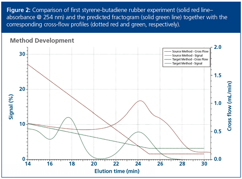
The result of this experiment, depicted in Figure 2 by the solid red line together with the applied cross flow as a dotted red line, revealed that two size populations are present but they eluted at, and beyond, the end of the crossâflow gradient at 25 min. To improve the separation of these fractions, the same strategy as above was followed and the initial cross flow was lowered to 1 mL/min while increasing the end value to 0.2 mL/min to elute both fractions earlier, but with more separation. The predicted fractogram is plotted as a green solid line in Figure 2.

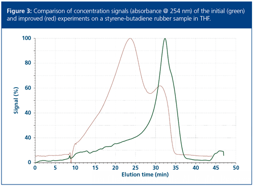
The outcome of the second physical experiment with the refined method is graphed as a solid red line in Figure 3, overlaid with the first experiment in green. Figure 3 confirms the success of the new method, although the first-eluting fraction was not shifted as much as predicted, possibly as a result of nonâsteric interactions with the membrane. The refined method did achieve a clear improvement of the separation performance, albeit without baseline separations.

Conclusions
The feasibility of fast, easy method development in flow-FFF using simulation software and a combination of virtual and physical experiments has been demonstrated through two examples. The nanoparticle application consisted of a trimodal polystyrene mixture in aqueous mobile phase, while the polymer application optimized the separation of a styreneâbutadiene rubber dissolved in THF. Following this protocol, novice FFF users may rapidly gain intuition regarding method design and optimization, while expert users see a major boost to productivity.
By using simulation software, method development in flow-FFF is wholly rationalized. Tedious method development based on multiple runs by trial-and-error is not necessary, which avoids the concomitant cost in time and materials. Furthermore, the software provides sample analysis, automatically calculating hydrodynamic size distributions. Hence, in addition to the enhanced separation method development capabilities, flow-FFF with simulation software directly contributes quantitative information to the already extensive sample characterization data provided by downstream light scattering instrumentation or inductively coupled plasma–mass spectrometry (ICP-MS).
References
- J.C. Giddings, M.N. Myers, G.C. Lin, and M. Martin, J. Chromatogr. A 142, 22–38 (1977).
- M.E. Hoque, K. Khosravi, K. Newman, and C.D. Metcalfe, J. Chromatogr. A 1233, 109–115 (2012).
- J.C. Giddings, G.C. Lin, and M.N. Myers, J. Liquid Chromatogr.1, 1–20 (1978).
- M.A. Benincasa and J.C. Giddings, Anal. Chem. 64, 790–798 (1992).
- A.J. Bednar, A.R. Poda, M.D. Mitrano, A.J. Kennedy, E.P. Gray, J.F. Ranville, C.A. Hayes, F.H. Crocker, and J.A. Steevens, Talanta104, 140–148 (2013).
- F. Kammer, M. Baborowski, and K. Friese, Anal. Chim. Acta 552, 166–174 (2005).
- P. Wyatt, Analytical Chemistry86(15), 7171–7183 (2014).
- C. Johann, A. Kaltenborn, H. Schuch, and M. Schumacher, Patent WO: PCT/EP2008/008184, EP:2104853, 2010.
- C. Johann, S. Elsenberg, H. Schuch, and U. Roesch, Anal. Chem. 87(8), 4292–4298 (2015).
Stephan Elsenberg is head of the R&D and application laboratory at Superon GmbH. Superon is a spin-off company from Wyatt Technology Europe GmbH that develops and manufactures software and hardware for FFF. He studied applied environmental sciences at the University of Trier, specializing in analytical and ecological chemistry, and was employed by Shimadzu Germany GmbH before joining Wyatt Technology Europe and then Superon.
Christoph Johann founded Wyatt Technology’s subsidiary company, Wyatt Technology Europe GmbH. He has been active in polymer, biopolymer, and protein analysis for nearly 30 years, earning his Ph.D. in physical chemistry at the University of Mainz and cofounding PSS Polymer Standards Service GmbH prior to establishing Wyatt Technology Europe.
E-mail:info@wyatt.comWebsite:www.wyatt.com/Eclipse

Retaining Talent in Field-Flow Fractionation: An Initiative
The authors present their motivation for establishing the Young Scientists of FFF (YSFFF) initiative within the FFF community.
Developments in Field‑Flow Fractionation Coupled to Light Scattering
December 8th 2020Field-flow fractionation (FFF) coupled to light scattering is a powerful method to separate and characterize nanoparticles, proteins, and polymers from a few nanometres to a few micrometres. The technique is one of the few that can cover the full size range of nanomaterials and provide high-resolution size distributions and additional characterization. New developments in FFF enhance performance and productivity.


