The Development and Applications of PLOT Columns in Gas–Solid Chromatography
LCGC North America
GC expert Jaap de Zeeuw explores the historical development of PLOT columns, covers details of the most popular stationary phases, and provides practical hints.
Gas chromatography (GC) had its beginnings in the early 1950s with the famous Nobel Prize winner A.J.P. Martin and his colleague A.T. James demonstrating the feasilibility of GC (1). They provided the guidelines for separations in the gas phase but GC had its development via very smart scientists like Desty (2), Golay (3), Ettre (4), Giddings (5), and many others, who had a remarkable power of combining technologies with creativity to foresee unique solutions for separation challenges. Initially, the work started with chromatographic separations using packed-bed columns, but the level of separation power moved to another magnitude by using the capillary columns. In the early days of capillary GC, most of the work was done using metal columns, which gave many issues in efficiency and inertness, but when glass capillaries were used (Figure 1), it was possible to make highly inert and efficient columns. The internal glass surfaces could be modified relatively easily to coat nonpolar as well as polar phases using surface roughening and silane-deactivation techniques.

Jaap de Zeeuw
Despite the excellent chromatographic characteristics of glass, the practical issues of column installation were always a big problem. Because both of the column ends had to be inherently straight for 10–12 cm to fit into injector and detector, this was a challenge for every chromatographer who had to install a glass capillary column. This was a problem not only for the user, but also for the manufacturer. I remember in the early days of our column manufacturing operation at Chrompak, our biggest problem was to find a suitable way to package the glass capillary columns to ship them all over the world while keeping the straightened ends in shape for future installation. Cutting off a piece of the column, as well as straightening the ends, was an art. However, some users found a way around that problem. For certain brands of GC columns, there were already cassette systems in which the glass capillary columns were mounted in a fixed frame. At the time, this was a very practical way to solve the shipping problem and even today, such a system would be highly appreciated.

Ronald E. Majors
To prevent having to straighten the ends, many columns were supplied with platinum-iridium tubing. This metal tubing is relatively inert and could be melted onto the ends of the glass capillary columns, creating flexible ends on both sides. However, there was also a challenge to straighten the platinum-iridium capillary tubing because it always tended to bend. Another challenge was to find the correct ferrule and get a good gas-tight seal. The outer diameter of the Pt/Ir tubing was 0.4–0.5 mm, considered very small in those days. Graphite ferrules had to be deformed heavily with all the risks of cold flow and resultant leaks.

Figure 1: Glass capillary column.
Another approach to packaging was the coating of a paraffin-film around the column. The glass column was doped in liquified "candle wax" before shipping. Of course, an application sheet was sent with the column instructing the user to first put the column into hot water to remove the candle wax. As might be expected, we received some interesting phone calls from customers who exclaimed that their GC instrument was "smoking." Indeed, they had forgotten to take off the candle wax before placing the column in the hot oven!
The big change came in 1979 with the invention of fused silica (6). In just a few years, the glass capillary was completely replaced by the fused-silica columns, which solved a lot of the problems very simply because it was easy to use. The fused-silica column was flexible, so there was little risk for breakage. It was very easy to install as the ends were self-straightening. When column was contaminated, a piece could be cut off. Columns also could be coupled, and the surface was high-purity silica, so few impurities were present to interact with analytes. This application of fused silica was the start of a revolution in capillary GC, and the technique grew exponentially.
Stationary phases
A great deal of work has been done to explore the scientific applications and limitations of capillary GC. I had the opportunity to work with the former research group at the University of Eindhoven, The Netherlands (7), who did a tremendous job in laying out new concepts and foundations for high-speed capillary GC applications.
In addition to the fused-silica capillary advancements the stationary phase chemistry developed very fast, initially with the coating techniques, but also with the development in the bonding and cross-linking of different types of phases. Most of these phases were polymeric and were based on siloxane chemistry. Even today, this chemistry is still playing an important role in the development of new phases.
In my research work, I was personally interested in separation of volatile compounds. To separate volatile compounds using polysiloxane liquid phases, we always ended up making very thick films, which lose their efficiency rapidly because of the slow stationary phase mass transfer (that is, the resistance in the liquid phase when the component is dissolved and tries to get out). Due to their higher capacity, adsorption on solid sorbents coated onto the capillary tubing walls can separate volatile compounds without having to use thick layers.
Adsorbents
My interest in adsorbents started with packed-column applications. From the beginning of GC, volatile components were analyzed mainly using particulate adsorbents such as molecular sieves, porous polymers, carbon, silica gel, and alumina as stationary phases. On occasion, a combination of solids and liquids was used by coating active adsorbent surfaces with thin films of liquid phases. The adsorbents were packed into glass or metal tubes with outer diameters ranging from 1/16 to 1/4 in. (1–5.3 mm i.d.) for analytical work. Adsorption on these solid materials resulted in strong analyte interactions but packed columns were much slower and less efficient compared to the liquid coated open tubular capillary columns.
To mimic the packed columns, these solid adsorbents had to be coated onto the internal surface of the fused-silica capillary tubing. The coating processes for adsorbents are significantly different from the polysiloxane type phases used in gas–liquid chromatography. These new adsorbent-coated capillary columns were (and still are) referred to as porous layer open tubular (PLOT) capillary columns. Physically, the PLOT columns look different as the coating of a white or black "powder" will give the column a unique appearance, as can be seen in Figure 2. The chromatography using these adsorbent solids is also remarkably different from gas–liquid phases. For instance, column overloading in gas–liquid chromatography results in a leading peak, while overloading in adsorption chromatography results in a more tailing peak as can be noted in Figure 3. Compared to liquid-coated phases, adsorbents are known to be very stable over time and they are difficult to "destroy." Liquid phase–coated columns can develop activity by hydrolysis or oxidation. In the case of adsorbents, the driving separation mechanism is already an active surface. Any additional activity created by hydrolysis or oxidation will generally have minor impact.
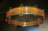
Figure 2: PLOT column, with typical "yellow" appearance due to white solid coating.
However, adsorbents have high retention for organic substances and any contamination in injector or carrier gas will accumulate on an adsorption column. For example, if PLOT columns are left overnight in flowing carrier gas steams at room temperature, in the morning they will need extensive conditioning as septum bleed and gas impurities are all trapped on the adsorbent surface.
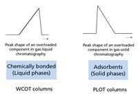
Figure 3: Peak shape of overloaded component in gasâliquid and gasâsolid chromatography.
Alumina
In looking at the challenge for light hydrocarbon separations, early on, alumina showed very interesting selectivity. However, the coating of alumina "particles" instead of soluble polymers was a new challenge for making GC capillary columns. Deposition of solid layers of adsorbents for PLOT column production required very stable suspensions. A very frequent problem for making such columns was always the plugging of PLOT columns after they were coated. After the adsorbent layer was deposited, it had to be dried and activated while the particles remained in place.
The first alumina PLOT columns made showed very high retention and far too much activity. To reduce the activity, the sorbent had to be wetted with water. One way to accomplish this wetting was to have the carrier gas deliver the water in a controlled manner. A nice solution to this problem was found by using copper sulfate crystals placed in a filter cartridge. By keeping this cartridge under constant pressure and temperature, the carrier gas was "humidified" in a constant and controllable way. This gave beautiful separations for hydrocarbons, but the setup could only be used under isothermal conditions, which limited the upper hydrocarbon range. Also, the slightest variation of laboratory temperature resulted in a change of water level and thus a change of retention.
The solution to this problem was not all that difficult: change the water for a more permanent deactivating molecule, a procedure that was accomplished based upon the work of Schneider, Frohne, and Brudereck (8), who did the work on glass capillary columns. Our group had to transfer this process from glass to fused silica. Initially, the dynamic coating process was very challenging to obtain sufficient layer thickness. After optimizing the thixotropic behavior of suspensions, this coating also was successful on fused-silica columns.
Instead of water, the columns were permanently deactivated with potassium chloride. As a result, the alumina PLOT column could be used in temperature-programmed analysis up to 200 °C, thus allowing hydrocarbons to be eluted up to decane. We also found that column polarity could be changed by using different deactivation salts. Sodium sulfate as well as sodium molybdate also could be used, which created more polar alumina surfaces. Later, this technology also was applied in smaller internal diameter columns. At Restek (Bellefonte, Pennsylvania), we went down to 0.18 mm diameter with Rt-Alumina BOND/KCl (Figure 4). However, with smaller internal diameter columns, the chromatography became very challenging due to minimal loadability.
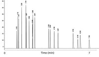
Figure 4: Light hydrocarbons separated on Rt AluminaBOND/KCl. Column dimensions: 30 m à 0.18 mm; oven temperature: 100 °C. Peaks: methane, ethane, ethylene, propane, cyclopropane, propylene, acetylene, propadiene, isobutane, butane, trans-3-butene,1-butene, isobutene, cis-2-butene, isopentane, propyne, pentane, 1,3-butadiene.
Regretfully, until now, the alumina PLOT columns have been applied mainly to hydrocarbon separations. If water, CO2 or any other polar compounds are present in the sample or carrier gas, they will be adsorbed by the alumina and the retention times for hydrocarbons will change. After commercialization of the first fused-silica alumina column, workers in the hydrocarbon field appreciated the selectivity the alumina for hydrocarbons and this type of column became available from different commercial suppliers. Investigations were started in "other" adsorption-type columns. Alumina also was investigated for use in other application fields, like the chlorofluorocarbon (CFC) ozone precursors. Alumina separates these components very well, but the activity of the column does not allow measurement of every CFC component. Some compounds showed in-column decomposition, which is not unexpected considering the high activity and the high temperatures applied. By more intense deactivation, the reactivity can be reduced, but not completely eliminated (9).
Molecular Sieves
The next challenge in PLOT capillary column technology was the application of molecular sieves targeting the separation of permanent gases. We initially looked at the zeolite chemistries and were surprised by their immense possibilities. The growing of zeolites in situ under autoclave conditions was possible, and we investigated this technology. The experiment failed as the column exploded, leaving a GC oven full of dust along with a terrible smell caused by burning the polyimide outside coating on the fused-silica capillary column!
For the zeolite column, there was a lot of early work done by adsorption specialist Prof. Dr. Manfred Mohnke, who was working at the University of Leipzig, East Germany. At that time, the Cold War was still on and it was not easy to get in contact with scientists in the DDR. Dr. Mohnke was the developer of many adsorption columns in the early days of GC (10). However, a successful collaboration between our two labs was initiated with the goal of investigating different coating techniques for making molecular sieve (molsieve) columns. The challenge with molsieve compared with alumina is that the layers required are 10× thicker to get sufficient retention for permanent gases at temperatures above ambient (for example, 50 μm in 0.53-mm i.d. capillaries).
Molsieve columns were developed successfully, but we ran into testing challenges. To detect permanent gases with capillary columns, we also needed detection systems that could be used. The only systems available were the thermal conductivity detection (TCD) systems that were used for packed columns but those systems had huge cell volumes and minimum flow was 10–20 mL/min. Because the molsieve PLOT columns used only 2–3 mL/min, we needed to add make up gas, but lost sensitivity as a result. GowMac (Madison, New Jersey) was one of first instrument companies who made micro TCD systems and we successfully used one for our work. Later, Hewlett-Packard (now Agilent Technologies, Santa Clara, California) developed their flipflop TCD system for capillary columns. Still, compared with flame ionization detection (FID), TCD is 50–100× less sensitive, which meant that the molsieve column needed to possess a higher loadability. For this reason, the use of smaller bore molsieve columns for laboratory applications had been limited. Things changed when the chip TCD systems were developed. Those systems have detection limits approaching 1 ppm and they can work with flow rates produced by 0.15–0.25 mm columns.
Working with molsieves also opened a new separation mechanism in GC that is based upon size exclusion. Permanent gases are separated because they have access to the enormous surface inside the zeolite pores. Molecules that cannot enter the pores will be retained only by the outside surface, which has a much smaller surface area. Components that cannot enter the pore will be eluted faster. For example, isobutane is eluted before methane, having a retention factor of approx 3 at 30 °C. While n-butane, because it is linear, can enter the pore and shows huge retention with a retention factor >> 100.
Molsieves are used widely, but have very limited application range. Similar to alumina, water and CO2 are adsorbed and need very high temperature to elute them from the zeolite PLOT columns. It would be nice to see the development of some hydrophobic molsieve materials.
Porous Polymers
The porous polymers were widely known under the names Porapak (Waters, Milford, Massachusetts) and Hayesep (Hayes Separations, Bandera, Texas) in the packed-column era. The base material is a porous structure of polydivinylbenzene. With this polymeric material, different functional groups can be incorporated to create various selectivities. Most widely known is the "Q" type polymer. The porous polymers have interesting characteristics as they have high retention, are highly inert, and elute both polar and nonpolar compounds. Also, the porous polymers can be coated onto the fused-silica capillary columns, but the coating process becomes more challenging. Porous polymers have the habit of developing an electrical potential, making the particles quite static, especially when particle-size has to be reduced. Once the particles are in suspension, this is not an issue but after the solvent is removed, when particles are isolated where they can move, one can expect trouble. If such effects occur inside the PLOT capillary column, the coatings can become unstable and the particles can be eluted and plug the columns. When columns are transported, used in valve switching or placed a vibrating environment, the polymer particles can be released.
To prevent particulates from reaching the detector, where they can produce spikes, or to switching valves that can be damaged, a simple solution was developed that was called a "particle trap." Such particle traps are 1–2 m long pieces of normal polydimethylsiloxane (PDMS)-coated fused-silica capillary column coupled between the column and the valve or between the column and the detector. The PDMS phase in the particle trap will act as "glue," trapping any particles that are released. The extra retention generated by the PDMS capillary column can be neglected because the retention of the adsorbent is several magnitudes higher than the liquid phase. This solution works quite well if the particle release is moderate. If particles are released by the thousands, the particle trap will also start to plug.
There has been ongoing research in stabilization of porous polymers using stabilizers, in situ preparation of porous layers (11,12) and in situ gluing but the stability still has not been at a comparable level to bonded liquid phases. When column switching is to be used, it is recommended to use the flow (so-called Deans) switching approach, in which pressure shocks are not as big as seen with valves. Because the porous polymer PLOT columns always can have some free-particle formation during transport, it is recommended to precondition fresh columns at a flow rate 50% higher than what will be used for analysis. To build in long-term security, one can always add particle traps or other screens between the column and switching device.
Chemically, the porous polymer PLOT columns are highly inert and they separate polar volatiles like alcohols and aldehydes as well as hydrocarbons — Figure 5 shows the use of an Rt-U-BOND column (Restek Corp.) to separate polar volatiles. Porous polymers can be modified by including vinyl-pyridine or acrylate groups to create higher polarity. As with the liquid phases, the maximum operation temperatures of porous polymers drops when the polarity of the phase is increased.
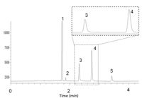
Figure 5: Polar volatiles on porous polymer PLOT column. Column: 30 m à 0.53 mm fused-silica Rt-U-BOND, df = 20μm; oven temperature: 100 °C; carrier gas: H2; injection: split; detection: TCD. Peaks: 1 = N2 + O2 + CO, 2 = CO2, 3 = formaldehyde, 4 = water, 5 = methanol.
Silica
Silica gel is not used widely in GC, as only few applications have been developed on this material. It remains an interesting material because it has high retention for hydrocarbons and it also can be used to separate a range of semipolar compounds. Silica gel is the perfect precolumn if low parts-per-million oxygen has to be measured in hydrocarbon stream. Normally, porous polymers could be used, but trace oxygen gets removed by the porous polymer, not by the silica gel. Commercialization of silica-coated columns like Gaspro (Supelco, Bellefonte, Pennsylvania) and SilicaPLOT (Agilent Technologies) (13), revealed that selectivity wise, the silica did very well in the C1–C3 range, but C4 isomers tend to be eluted closer as also can been seen with porous polymers. An important characteristic of silica is that this material separates sulfur compounds at parts-per-billion levels. The sulfur compounds are well resolved from hydrocarbons, which made the parts-per-billion analysis of H2S and COS in propylene–propane possible, as can be seen in Figure 6. Silica-coated columns are also much less sensitive to moisture, a big advantage over alumina. However, the poor selectivity for C4–C5 hydrocarbon isomers limits its use for light hydrocarbons. Aside from the sulfur compounds, chloro-fluoro compounds and ethers can be separated on silica PLOT columns. One of the big challenges using silica is, similar to high performance liquid chromatography (HPLC) packings, that the manufacture of reproducible silica surfaces is difficult. One of the outcomes of this challenge is the apparent variation of trace sulfur response that seems to be difficult to control among columns as well as among suppliers.

Figure 6: Separation of trace sulfur compounds in propylene using a silica PLOT column. Column: 30 m à 0.32 mm CP-SilicaPLOT; oven temperature: 50 °C, 1 min to 120 °C, 10°C/min; detection: Antek SCD. Peaks: 1 = H2S, 34 ppb; 2 = COS, 108 ppb. (Varian application note 1293 at www.varianinc.com/cgi-bin/scanweb/scanview.)
Carbon
Active carbon is also of interest because of its low polarity and huge surface area. Like the porous polymers, it is very nonpolar, but with much higher retention and significantly lower retention compared to zeolite molecular sieves. With carbon, CO2 is eluted as a sharp peak and if layers can be built to 10 μm or thicker, CO can be resolved from air. However, thick layers of carbon are not easy to make. Also, working with these powder suspensions is very challenging because any contact will immediately give black spots (fingers as well as labware).
There are different ways to make carbon-type PLOT columns, suspensions, pyrrolysis, or carbon nanotubes. It's all about getting enough surface. A unique application of carbon PLOT columns is the separation of acetylene from the main ethylene matrix. If impurity analysis is the goal, it is usually preferable to have the impurity eluted before the main component. The carbon PLOT column shows ideal selectivity because carbon materials are very nonpolar as can be seen in Figure 7, showing the analysis of 3-ppm acetylene in ethylene using a CarboBOND (Agilent Technologies) column.

Figure 7: Separation of impurities in ethylene. Column: 25 m à 0.53 mm CP-CarboBOND, df = 10 μm; oven temperature: 35 °C, 1 min to 180 °C, 10°C/min; sample: 3-ppm acetylene in ethylene. Peaks: 1 = methane, 2 = acetylene, 3 = ethylene, 4 = ethane, 5 = propane. (Varian application note 1433 at www.varianinc.com/cgi-bin/scanweb/scanview.)
For components with very small k values, the use of packed columns remains an interesting option. Recently, packed columns have been miniaturized, by filling 0.53-mm deactivated stainless steel tubing with adsorbents like carbon, molecular sieves, and porous polymers (14). Such columns show promise for simple fast separations that can be performed in any instrument. Figure 8 shows an example on a 1 m × 0.53 mm MXT Shincarbon (Restek Corp) micropacked column. Such columns can be coiled in small diameters and operate at flow rates of 2–4 mL/min.
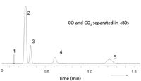
Figure 8: Separation of CO and CO2 using carbon 0.53-mm i.d. micropacked column. Column: 1 m à 0.53 mm MXT, Shincarbon 80/100 mesh (Restek); oven temperature: 100 °C, carrier gas: He, 165 kPa; split: 1:30; detection: micro-TCD. Peaks: 1 = hydrogen, 2 = oxygen + nitrogen, 3 = CO, 4 = methane, 5 = CO2.
Special Selective PLOT Columns for Oxygenates
Several highly selective PLOT columns have been developed (CP-Lowox, OxyPLOT, Agilent Technologies) with a unique selectivity toward oxygenated compounds (13). Though the technology is proprietary, these columns have a polarity that is tremendously high. Methanol is eluted after C14, allowing oxygenated compounds to be separated nicely from a paraffin matrix (see Figure 9). As oxygenated compounds are known as "catalyst-killers" in hydrocarbon processing, the determination of trace oxygenates is a very important analysis. Using oxygen-selective columns allows the accurate determination of parts-per-billion levels of oxygenates. When used with a nonpolar precolumn in which the higher hydrocarbons are separated from the volatile fraction, one can use this setup for measuring parts-per-billion levels of oxygenates in naphtha streams.
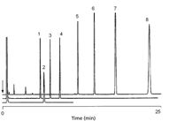
Figure 9: Highly selective PLOT column for oxygenated compounds. Column: 10 m à 0.53 mm CP-Lowox; oven temperature: 175 °C, 2 min to 175 °C, 10 °C/min; carrier gas: He, 70 kPa. Peaks: 1 = C14, 2 = methanol, 3 = C15, 4 = C16, 5 = C18, 6 = C20, 7 = C22, 8 = C24. (Varian application note 1363 at www.varianinc.com/cgi-bin/scanweb/scanview.)
Metal Columns
Another challenging area for the analysis of volatile compounds is the use of portable and the process gas chromatographs. Portable instrumentation requires columns wound into small diameters, a challenge for fused silica. It's not a problem to wind 0.25-mm i.d. fused silica to a 4–5 cm diameter, but the smaller internal dimeter columns also have very low sample capacity. On a practical basis, a high sample load is preferred, offering sufficient linearity. The column-winding diameter must be small, meaning 0.32–0.53 mm i.d. capillaries should be used. If fused silica is wound that small, there is a risk that columns will break due to ring-tension. In this application, a metal column will be very welcome because it can be coiled to a small size without risk for column breakage (see Figure 10).

Figure 10: Metal tubing can be wound in small radius, allowing small column designs without risk of breakage; paper clip provided for size comparison.
Metal columns already are used extensively in process applications. In this type of application, there is a preference for robustness, in which fused-silica capillaries are considered to be more risky. In the last century, it was discovered that metal columns can be deactivated using a silicon deposition process (Silcosteel, Siltek, Restek Corp). Combined with a secondary deactivation, a surface was created having near similar inertness as fused silica. A large series of different phases and adsorbents were made commercially available in 0.53-mm deactivated metal columns, allowing phase selectivity to be used for optimization.
Process analyzers need to be extremely reliable: they need to run 24 hours per day, 7 days a week, with minimal and predictable maintenance. Many process type applications as done in the petroleum and chemical industries are optimized for shortest cycle times and use smart column-switching systems. Most methods are isothermal, which are the most reliable. In this application field, there is an interest in using the PLOT columns to take advantage of their efficiency and flexibility. The metal PLOT columns must be very robust and predictable. Today's metal PLOT column types with molecular sieves, alumina, and porous polymers do show very promising behavior to be used for the process-type industries as well as for miniaturization, as is required in portable GC (16). Figure 11 shows a typical separation obtained on a MXT-Molsieve 5A (Restek Corp.) column. Peak shapes are excellent, even for the highly retentive carbon monoxide.
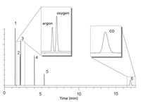
Figure 11: Permanent gases on metal Molsieve PLOT column. Column: 30 m à 0.53 mm MXT-MSieve 5A, df = 50 μm; oven temperature: 30 °C; carrier gas: H2; injection: split; detection: micro-TCD. Peaks: 1 = helium, 2 = argon, 3 = oxygen, 4 = nitrogen, 5 = methane, 6 = carbon monoxide.
Stability
PLOT columns generally are made by conglomerates of particles that are deposited as a layer inside of the capillary. The layer is porous, meaning that the gas pressure inside the column also will be present between the individual particles. If pressure or flow suddenly changes, the particle layer can explode, as the pressure will find its way out, destabilizing the particles (see schematic in Figure 12). That's why PLOT columns remain more vulnerable for nonreproducible flow behavior than the liquid phase–coated columns. This is becoming an increasing challenge with wider implementation and availability of flow switching techniques by a variety of gas chromatography instrument manufacturers. Methods have been put in place to measure the flow restriction of PLOT columns and make this a test parameter. An easy way is to inject a nonretaining component onto a PLOT column at a certain temperature. The retention time can be related to the retention on a noncoated capillary of the same dimensions (12).
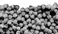
Figure 12: Graphical representation of PLOT surface. Pressure in cavities will expand when pressure on top is changing, creating eruption of particles.
Stability testing is not well defined. I recall that a space agency developed a method for analyzing volatiles in a planet's atmosphere. This was all done on a porous polymer PLOT column. Excellent separation was obtained, but they did not realize what the impact of the gravitation during launch would do to such a PLOT column.
So they purchased four new columns and they went through the gravitation tests. The end result was that the columns were completely blocked and they had to look for a different method, this time doing the gravity experiment first, and then developing the separation methodology.
Another way for testing stabilization was done by a company that used the columns in a portable instrument. To make sure that only the strongest bonded particles remain, they pressurized the PLOT column with a pressure up to 6000 kPa (840 psi). After a few seconds, they opened both ends and usually a large cloud of particles were blown out of the columns. It was a bit rough, but at the time it seemed to work.
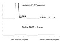
Figure 13: Impact of pressure pulse program on a unstable and a stable PLOT column. GC system: Agilent 6890; carrier gas pressure program: hydrogen, 3.0 psi, hold 1 min; 50 psi/min to 10.0 psi, hold 1 min; 50 psi/min to 3.0 psi, hold 1 min; 50 psi/min to 10.0 psi, hold 1 min.
Of course, you also can take a PLOT column on the back of a mountain bike, but it would be nicer to have a bit better control on the technical conditions. One way is to use the pressure-pulse capability as is offered with most modern GC instrumentation. By running systematic pressure pulse programs, one can simulate and compare the impact. When a particle is detached from the wall, it will be eluted, creating an electronic "spike" in the FID. The intensity of "spikes" is a good indicator of the stability (see Figure 10).
PLOT Columns in MS
Very often it is asked whether or not PLOT columns can be used in a mass spectrometer. The challenge is the high vacuum present in the mass spectrometer and the relative low flows that are used with mass spectrometry (MS). To limit the flow rates, we could use 0.25-mm i.d. PLOT columns, but then we will run into sample capacity problems. If we use the higher capacity 30 m × 0.32 mm columns, we have the flow–vacuum problem.
The MS vacuum makes the linear velocity at the last part of the column extremely high, increasing the risks of particle release that would contaminate the ion source.
However, we have found that this can be prevented easily by coupling the PLOT column with coated restriction tubing. Using a 5 m × 0.25 mm section of fused silica coated with a 0.2–0.5-μm thick polysiloxane layer will help in two ways: it will take care of the pressure drop caused by the vacuum, and if a free particle is formed, the siloxane coating will trap the particle. This setup can be used also for all 0.53-mm PLOT columns, fused silica as well as metal.
Though we are not working at optimal flow conditions, we can benefit from the high selectivity, loadability, and retention the PLOT columns offer. The only remaining challenge is to make a leak-free coupling when connecting columns to an MS system.
Conclusions
The development of PLOT columns has come a long way since the beginning of gas–solid chromatography. Despite some problems with the adsorbents tightly attaching themselves to the inner wall of a fused-silica or metal capillary, there are many difficult applications problems, especially in the hydrocarbon industry, that are solved more easily by the application of these columns. It is anticipated that further developments will occur in PLOT technology.
Acknowledgments
Thanking all "PLOT" contributors I had the opportunity to work with, in chronological order: from Chrompack/Varian: Rene de Nijs, Manfred Mohnke, Jan Peene, Coen Duvekot, Peter Heijnsdijk; From Dow Chemical: Jim Luong, Ronda Gras, Aaron Eidt; From Russian Institute for Petroleum: Victor Berezkin and from Restek Corporation: Bill Bromps, Tom Vezza, Rick Morehead and Gary Stidsen.
Jaap de Zeeuw studied six years of chemistry and graduated in 1979. His thesis was entitled "Fused Silica Capillary Column Technology." He has 31 years experience in GC capillary technology, developed many PLOT columns as well as simple concepts for fast GC–MS using a vacuum inside the column. He worked 27 years for Chrompack/Varian (now part of Agilent) and presently serves as an international GC specialist for Restek in the Netherlands. He has traveled widely and is well known and has many publications in the field of GC.
Ronald E. Majors "Sample Prep Perspectives" Editor Ronald E. Majors is Senior Scientist, Columns and Supplies Division, Agilent Technologies, Wilmington, Delaware, and is a member of LCGC's editorial advisory board. Direct correspondence about this column to "Sample Prep Perspectives," LCGC, Woodbridge Corporate Plaza, 485 Route 1 South, Bldg F, First Floor, Iselin, NJ 08830, e-mail lcgcedit@lcgcmag.com
References
(1) A.T. James and A.J. Martin, Biochem. J. 50, 679–690 (1952).
(2) D.H. Desty, A. Goldup, and B.H.F Whyman, J. Inst. Petrol. 45, 287–289 (1959).
(3) M.J.E. Golay, "Theory and Practice of Gas Liquid Partition Chromatography with Coated Capillaries," in Gas Chromatography, V.J. Coates, H.J. Noebels and I.S. Fagerson, Eds. (Academic Press, New York, 1958), pp. 1–13.
(4) L.S. Ettre, Instr. News 13(1a), 1–6 (1961).
(5) J.C. Giddings, Anal. Chem. 36, 1170 (1964).
(6) R.D. Dandeneau and E.H. Zerenner, High Resolut. Chromatogr. Chromatogr. Commun. 1, 351–356 (1979).
(7) C.A. Cramers and P.A. Leclercq, CRC Crit. Rev. Anal. Chem. 20, 117 (1988).
(8) W. Schneider, J. Frohne, and H. Brudereck, J. Chromatogr. 155, 311–327 (1978).
(9) J. de Zeeuw and T. Vezza, Poster B.09, "A new selective GC Column for CFC based on alumina," 34st Int. Symposium on Capillary separation Technologies, Riva del Garda, Italy, 2010.
(10) M. Mohnke and W. Saffert, Preprints of the 4th International Symposium on Gas Chromatography, Hamburg, Germany, June 13–16, 214–219.
(11) J. de Zeeuw, N. Vonk, M. Mohnke, D. Estel, and C. Duvekot, Int, Lab., 18–22 (1999).
(12) J. de Zeeuw, B. Bromps, T. Vezza, G. Stidsen, and R. Morehead, Amer. Lab. 42(5), 38–41 (2010).
(13) M. Mohnke, D. Estel, J. de Zeeuw, and C. Duvekot, Am. Lab. 29(4), 22–24 (1997).
(14) J. de Zeeuw, G. Stidsen, and R.Morehead, Poster E.09: "Using Packed Adsorbents in 0.53mm Wide Bore Metal Columns," 34th Int. Symposium on Capillary separation Technologies, Riva del Garda, Italy, 2010.
(15) J. de Zeeuw, N. Vonk, M. Mohnke, D. Estel, and C. Duvekot, Amer. Lab. News, 81–82 (1999).
(16) J. de Zeeuw, G. Stidsen, T. Vezza, and R. Morehead, Poster E.10: New Generation Stabilized PLOT Columns to Full Metal 0.53mm, 34th Int. Symposium on Capillary Separation Technologies, Riva del Garda, Italy, 2010.

New Study Reviews Chromatography Methods for Flavonoid Analysis
April 21st 2025Flavonoids are widely used metabolites that carry out various functions in different industries, such as food and cosmetics. Detecting, separating, and quantifying them in fruit species can be a complicated process.
University of Rouen-Normandy Scientists Explore Eco-Friendly Sampling Approach for GC-HRMS
April 17th 2025Root exudates—substances secreted by living plant roots—are challenging to sample, as they are typically extracted using artificial devices and can vary widely in both quantity and composition across plant species.
Sorbonne Researchers Develop Miniaturized GC Detector for VOC Analysis
April 16th 2025A team of scientists from the Paris university developed and optimized MAVERIC, a miniaturized and autonomous gas chromatography (GC) system coupled to a nano-gravimetric detector (NGD) based on a NEMS (nano-electromechanical-system) resonator.

.png&w=3840&q=75)

.png&w=3840&q=75)


.png&w=3840&q=75)


.png&w=3840&q=75)


