Contaminants Everywhere! Tips and Tricks for Reducing Background Signals When Using LC–MS
LCGC North America
We examine instances where contaminants are problematic in LC–MS, as well as successful methods to decrease their influence.
I spend time with each new group of students taking my Instrumental Analysis course making the point that modern mass spectometry (MS) is a double-edged sword. On one hand, modern instruments are incredibly sensitive, enabling scientists to detect molecules of all kinds, often in very complex matrices, at concentrations much lower than could be imagined 20 years ago. This improved sensitivity has enabled tremendous advances in fields ranging from environmental science to proteomics. On the other hand, this same sensitivity results in observing molecules that we would rather not see during our analyses, because in some way they interfere with detection of analytes of interest. In this installment of LC Troubleshooting, I will discuss this issue of the things we don't want to see, which I will generally refer to here as "contaminants." Why are they a problem? Where do they come from? And finally, how can we minimize these problems?
Why Are Contaminants a Problem?
There are three major reasons why contaminants are a problem. The first is that they can contribute substantially to the background ions that contribute to the baseline we observe in all liquid chromatography–mass spectrometry (LC–MS) chromatograms. Even if we have a system that is perfectly free from contaminants, there will be background signal because of the detection of solvent cluster ions. However, addition of even very low concentrations of highly ionizable compounds to the mobile phase can significantly increase the level of the background signal. This increased background signal can make it challenging to detect molecules of interest, particularly in cases where we don't know what we are looking for a priori, as is the case in so-called untargeted analysis.
The second major reason that contaminants are a problem is that they can present themselves as ions in the mass spectrometer with the same mass-to-charge ratios (m/z) as our target analytes so that they interfere with the detection of the compounds of interest. Modern high-resolution spectrometers can address this problem to some extent by separating ions with very slight differences in the mass domain, but even with a spectrometer of the highest available resolution, any contaminant with the same elemental formula as a target analyte will be detected with the same m/z value. Ion mobility and tandem MS can further address this issue, but even in these cases interferences can be a problem.
Finally, the third reason is that contaminants can enhance, or, more commonly, suppress the ionization of analytes of interest. In some cases, this enhancement or suppression will cause errors in quantitation unless isotope-labeled internal standards are used. In extreme cases of suppression, it may be so severe that analytes of interest are not detected at all. At this point, I am reminded of a situation that we encountered a few years ago in my own laboratory. At the time, we were developing a method for characterization of an intact protein by reversed-phase LC–MS. The mobile phase was very straightforward, containing only acetonitrile, water, and 0.1% formic acid. In one instance, the system was working well on a Friday, but, on the following Monday, we did not observe any protein signals in the mass spectrometer at all. Given the apparent sudden and dramatic change in sensitivity, we thought something was seriously wrong with the mass spectrometer. After engaging a service engineer in extensive troubleshooting and diagnostic work, we concluded that the mass spectrometer was working just fine. Thinking through our workflow more carefully, we realized that a new source of formic acid was used to prepare fresh mobile phase on Monday. The formic acid used previously was contained by a glass bottle, whereas the new formic acid was contained by a plastic bottle (even though this material was marketed as an additive for LC–MS!). After fresh mobile phase was prepared using the previously used formic acid source, the protein signal in the MS instantly returned to normal, suggesting that something in the new formic acid source was very severely suppressing the ionization of our protein of interest. To this day, we do not know what the contaminant was in the formic acid causing this problem, but it is a great example of how contaminants can appear from unexpected sources and have dramatic effects on LC–MS results.
Where Do Contaminants Come From?
A simple view of analysis by LC–MS is that the only things that enter the mass spectrometer are the mobile-phase constituents and additives, and the analyte of interest when it is eluted from the chromatography column. In a typical case, these components would be acetonitrile, water, and formic acid from the mobile phase, and then the analyte of interest, such as ibuprofen. In reality, however, the situation is far more complex. With every LC–MS system in operation, there are literally hundreds of possible ways that contaminants can enter the system, and ultimately interfere with the analysis of target analytes. When I talk with students about quantitation, particularly for trace level analysis, I emphasize that one must think carefully about all of the ways that the target analyte can be lost in the analysis process. For example, will the analyte be lost by adsorption to centrifuge tubes, syringe filters, or glass vials?
When discussing contaminants, we have to think about things from the reverse point of view-that is, we must identify the steps in the analysis that could possibly contribute contaminants to the system. In preparing for this installment, I communicated with several colleagues about the problem of contamination in LC–MS, and one application specialist who has been working with LC–MS for decades described the issue very well. "I can definitely say that many people complain about background interference," the application specialist said, "yet you see them preparing solvents and samples with bare hands. Lipids and amino acids, and probably some of your lunch and snacks, can be transferred to your mobile phase, samples, and solvent lines. Inasmuch as solvent lines are permeable, your dirty hands join in the confusion about how to eliminate background."
So, as users of LC–MS, we must adopt the mindset that every step in the analysis presents potential for introducing contaminants, and then develop work habits that at least will minimize problems with contamination, even if it is effectively impossible to eliminate them completely. The following list, though not exhaustive, describes some of the most common ways that contaminants can enter a LC–MS workflow (more-complete lists of potential sources of contaminants can be found elsewhere [1]):
Common Sources of Contamination
- Solvents: Compounds related to microbial growth in solvent reservoirs; compounds that leach from membrane filters during solvent filtration; solvent impurities; compounds that dissolve in the solvent from laboratory air; dust from laboratory air; compounds from solvent bottle covers (for example, parafilm, plastic caps, and paper-lined caps); residual detergents from washing solvent bottles
- Samples: Keratins and other biomolecules (for example, lipids, peptides, and amino acids) from skin and hair of the analyst; plasticizers from sample containers and sample preparation components (for example, pipette tips, vial inserts, and solid-phase extraction tubes); high-concentration sample components that are carried over from one analysis to the next (for example, lipids or proteins)
- LC–MS instrumentation: Compounds from contaminated solvent inlet filters (that is, in the solvent bottle at the end of the solvent line; these could result from microbial growth or particulate matter that has accumulated on the filter); compounds from contaminated solvent inlet lines (that is, from bottle to pump), either inside the tubing (for example, microbial growth) or outside the tubing (for example, introduced by handling the tube with bare hands, then pushing the solvent line into the solvent); compounds leaching from instrument components (for example, fluorinated compounds leaching from fluoropolymer seals, and compounds introduced by samples that stick to glass, metal, or plastic and are carried over from one analysis to the next)
Best Practices for Minimizing Contamination
Because of the importance of identifying interferences in LC–MS analyses, many workers have spent a great deal of time tabulating the m/z values of observed interferences, and where possible, identifying them. To the best of my knowledge, the most comprehensive collection of such knowledge that is publicly available was published by Keller, Whittal, and coworkers (2), and provides the information in large tables that can be downloaded for free. These tables can be quite helpful when developing strategies to reduce the level of specific contaminants, because they also provide likely identities and sources for many known contaminants (for example, ions observed due to Triton detergents). Nevertheless, adoption of best practices for minimizing introduction of contaminants into LC–MS systems is a very good idea, with the hope that many problems can be prevented. The following list of best practices is not exhaustive, but it provides a good starting point (additions to this list can be found in LC–MS vendor documentation and training materials [1,3]):
- Wear nitrile gloves when handling instrument components, filling solvent bottles, and preparing samples. This practice will prevent unwanted transfer of biomolecules and other contaminants on the skin to the system (for example, by skin cells falling into sample vials, or transfer of contaminants to mobile phase solvent).
- Where possible, minimize filtering of mobile-phase solvents. Most HPLC- and LC–MS-grade solvents (for example, water and acetonitrile) from mainline vendors are filtered to 0.2 µm at the time of manufacture. As long as the bottle is carefully covered after opening, these solvents do not need to be filtered again before use. Furthermore, filtering them in the laboratory introduces significant risk of contamination unless the filtration apparatus is scrupulously cleaned and kept dust-free, and membrane filters are rinsed to reduce leaching (3,4).
- Use mobile-phase additives (for example, formic acid, ammonium acetate) with great care. In principle, additives that are marketed for LC–MS applications should be both free from particulates and free from contaminants that might enhance or suppress ionization for analytes of interest, and thus using LC–MS-grade additives is generally a good idea. However, one should seriously consider filtering mobile phases containing these additives, especially when they are used at high concentration (>>10 mM). When developing a new method, it is a good idea to compare results obtained with additives from different sources. These additives can be evaluated both in terms of their total contribution to background signals by comparing total ion chromatograms (TICs) obtained using additives from different sources, and by examining the ion abundance of target analytes obtained with these additives (5). In my laboratory, we find an additive source we like, and stick with it (that is, stick with the devil you know [see below]). Finally, take all necessary steps to prevent microbial growth in mobile-phase bottles and LC system solvent line components (1,4). This list of steps should include frequent emptying and filling of solvents rather than simply refilling them, adding low levels (for example, 10% (v/v)) of organic solvent to aqueous mobile phases, and flushing instrument solvent lines and components with organic solvent if the instrument will not be used for an extended period of time.
- Use dedicated solvent bottles for LC–MS. Dedicate specific bottles to specific instruments, and to specific solvents (for example, use one specific bottle for acetonitrile, one for formic acid in water, and so on), and don't wash them with detergent. The risk of contaminating mobile phases with residual detergent is simply too great. It is helpful to rinse bottles used for aqueous solvents with a small amount of high-quality acetonitrile or methanol before filling with more aqueous solvent. In cases where a bottle becomes badly contaminated from microbial growth or other sources it is probably best to simply replace it with a brand new bottle.
Reducing the Effects of Contamination Through Instrumental Means
Although adopting best practices will certainly be helpful for reducing background contamination, sometimes the most troublesome contaminants are so ubiquitous (for example, phthalates in laboratory air), or difficult to remove from the system, that we either have to simply live with them [6], or try to reduce or remove them in situ-that is, within the LC–MS instrument itself (7). Some highly experienced practitioners I have talked with about the topic of contaminants say that rather than continually hunt for the cleanest mobile-phase solvent they can buy, which can be very expensive, they instead carefully catalog and track known contaminants in lower quality solvents. I refer to this approach as "sticking with the devil you know." In other words, if we are going to have to deal with contaminants, in some ways it is easier to cope with low but consistent levels of a small number of contaminants in a particular solvent than it is to deal with a contaminant profile that may be cleaner in general, but frequently changing.

Figure 1: Flow diagram involving the use of a lipophilic trapping column (for example, C18-silica) between the aqueous pump and the sample injector. This approach will effectively trap lipophilic substances in the aqueous component of the mobile phase so that they do not reach the column and detector.
Inline Cleanup of Individual Solvents
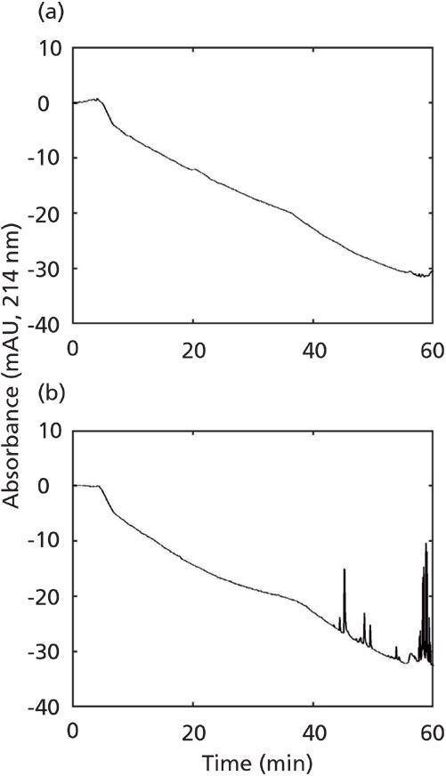
In addition to getting to know your solvents, there are modifications one can make to LC–MS instruments to reduce the level of contaminants reaching the detector, two of which I will describe here. The first approach, shown schematically in Figure 1, involves placing a trapping column inline between the outlet of the aqueous solvent pump head and the point where solvents are mixed before the sample injection point. This approach is similar in spirit to adding a trapping column between the solvent bottle and the pump as described by Taylor and coworkers (8); however, I think placing the trap downstream from the pump provides more flexibility in use of the instrument. This particular approach only works when individual mobile-phase constituents are pumped at high pressure individually, and then mixed; this setup is most commonly referred to as a binary pump with high-pressure mixing. Figure 1 shows that for reversed-phase applications a small column packed with a lipophilic adsorbent (the simplest case involves using the same chemistry as the analytical column) is installed between the outlet of the pump for the aqueous solvent and the mixing point. The adsorbent in this column, which can be any reversed-phase type of material, will strongly retain any contaminants in the aqueous phase that are significantly less polar than water. In this way the trapping column is used to effectively "clean up" the solvent online so that the contaminants never reach the analytical column and detector. In principle, this approach can also be used to clean up organic solvent mobile-phase constituents (for example, using a strong cation-exchange adsorbent to clean up acetonitrile [9]), although this approach is less commonly done in practice. Figure 2 is a representative example from my own laboratory showing the effect of the inline adsorbent on the level of contaminants observed at the detector. In this case a lipophilic trap was installed after the aqueous solvent pump, but before the mixing point. The reduction in detected contaminants is quite striking. Lahaie and coworkers have demonstrated that these contaminants can present themselves as interferences even when highly selective MS/MS detection is used (9).

Figure 2: Representative result from my own laboratory, showing the benefit of installing a cleanup column after the aqueous solvent pump in a high-pressure mixing system: (a) with and (b) without cleanup column. In this case the aqueous buffer was 10 mM ammonium bicarbonate in water at pH 9.5, the adsorbent was a polymeric reversed-phase material (chosen for its pH stability), and a solvent gradient of 2-40% acetonitrile was used over 60 min.
Inline Cleanup of Mobile-Phase Solvent Mixtures
A second inline solvent cleanup approach involves moving the adsorbent column so that it is located after the mixing point, but before the sample injection point, as shown in Figure 3. This approach has the advantage of extracting all of the mobile-phase contaminants that would otherwise be extracted by the analytical column itself, whether they are primarily present in the aqueous or organic components of the eluent. However, the disadvantage is that these compounds will be eluted from the trap as peaks when solvent gradient elution is used, and thus travel to the analytical column and detector, whereas using the adsorbent trap on an individual solvent line will hold the contaminants until the capacity of the adsorbent is reached (typically days or weeks). Nevertheless, this approach can be very useful, particularly in the case of targeted analysis as has been demonstrated for trace analysis of perfluorochemicals (PFCs) (10–12). Many modern analytical instruments contain a variety of fluoropolymer components, and these components of HPLC systems (for example, solvent tubing and seals) can slowly leach perfluorinated compounds that are target analytes in PFC analysis into the mobile phase. Although most LC–MS vendors provide instrument conversion kits for minimizing these contaminants, it is difficult to eliminate them entirely, and inline cleanup of the mobile phase is needed.

Figure 3: Flow diagram involving the use of a trapping column immediately before the sample injector. This approach will effectively trap substances in the mobile phase prepared by the pump and delay their elution relative to analytes in the injected column. In the simplest case the material in the trap column would be the same as the material in the analytical column.
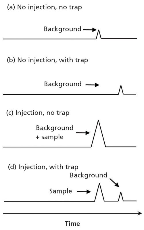
Figure 4 illustrates that two peaks will be observed for a given analyte when it is present both as a mobile-phase contaminant and in the analytical sample (see Figure 4d). This phenomenon can be understood by considering the four scenarios in Figure 4. In the first case, when no trap is used and no sample is injected (see Figure 4a), a peak will be observed for the analyte if it is present as a contaminant in the mobile phase. The compound is extracted from the mobile phase by the analytical column during column equilibration, and then is eluted from the column during solvent gradient elution. If we then add an adsorbent trap as is shown in Figure 3, the arrival of the contaminant peak at the detector is delayed by a time that is roughly the trap volume divided by the flow rate (see Figure 4b). Now, if we consider injecting a sample, first without a trap (see Figure 4c), we will see that the analyte peak appears at the same time as it did with no sample injected. In other words, whether the compound comes from the mobile phase or the sample, it appears at the same retention time and the peak area will be related to the sum of concentrations from both sources. Obviously, this presents a major problem for quantitative analysis. Finally, if we now add the trap back and inject the sample (see Figure 4d), we see that the analyte peak attributed to the sample stays in the same place, but the peak attributed to mobile-phase contamination is again delayed and separated from the peak of interest. This separation then enables more accurate quantitation and provides lower detection limits.

Figure 4: Illustration of the positions of analyte peaks originating from material in the mobile phase (that is contamination), and the sample, depending on whether or not an inline adsorbent trap is installed.
Summary
Modern LC–MS instrumentation is quite rugged and sensitive for analysis of many compound types. For optimal performance, however, great care must be taken to avoid contaminating the system with interfering compounds that can have a variety of effects on analyses ranging from direct interference (that is, contaminants having the same m/z value as analytes of interest) to indirect effects such as enhancement or suppression of ionization for target analytes. Adopting best practices that minimize the potential for contamination of the LC–MS system can be very effective and implemented at relatively low cost. For the most persistent interferences, minor instrument modifications can help remove trace contaminants and improve quantitative accuracy and detection limits of LC–MS methods.
References
(1) "Controlling Contamination in UltraPerformance LC/MS and HPLC/MS Systems" (2018). http://www.waters.com/webassets/cms/support/docs/715001307d_cntrl_cntm.pdf (accessed June 1, 2018).
(2) B.O. Keller, J. Sui, A.B. Young, and R.M. Whittal, Anal. Chim. Acta. 627, 71–81 (2008). doi:10.1016/j.aca.2008.04.043.
(3) "LC–MS Contamination Prevention" (2018). https://www.chromacademy.com/chromatography-LC-MS-Contamination-prevention.html (accessed June 1, 2018).
(4) D.R. Stoll, LCGC North Am. 35, 98–103 (2017) .
(5) H.M.D.R. Herath, P.N. Shaw, P. Cabot, and A.K. Hewavitharana, Rapid Commun. Mass Spectrom. 24, 1502–1506 (2010). doi:10.1002/rcm.4549.
(6) K. Hodge, S.T. Have, L. Hutton, and A.I. Lamond, J. Proteomics 88, 92–103 (2013). doi:10.1016/j.jprot.2013.02.023.
(7) A. Schlosser and R. Volkmer-Engert, J. Mass Spectrom. 38, 523–525 (2003). doi:10.1002/jms.465.
(8) M.R. Taylor, F. Harvey-Doyle, and K. Patel, LCGC Europe 28, 488–499 (2015) .
(9) M. Lahaie, N. Youhnovski, M. Furtado, and F. Garofolo, Rapid Commun. Mass Spectrom. 28, 886–892 (2014). doi:10.1002/rcm.6851.
(10) "Determination of Selected ASTM Perfluorinated Compounds (PFCs) Using the Shimadzu LCMS-8060" (2018). https://www.ssi.shimadzu.com/sites/ssi.shimadzu.com/files/Products/literature/lcms/083_Selected_ASTM_PFCs.pdf (accessed June 1, 2018).
(11) "PFC Analysis Kit for Acquity UPLC - System Guide" (2009). http://www.waters.com/webassets/cms/support/docs/pfc_analysis_kit_for_acquity_uplc_system_guide_reva.pdf (accessed June 1, 2018).
(12) A. Ruderisch, C. Dausch, and S. Fenzel, "Pitfalls and Prospects: Analysis of Perfluorinated Compounds (PFCs) Utilizing LC/MS/MS," poster presented at ASMS 2009.
ABOUT THE AUTHORS
Dwight R. Stoll

Dwight R. Stoll is the editor of "LC Troubleshooting." Stoll is a professor and co-chair of chemistry at Gustavus Adolphus College in St. Peter, Minnesota. His primary research focus is on the development of 2D-LC for both targeted and untargeted analyses. He has authored or coauthored more than 50 peer-reviewed publications and three book chapters in separation science and more than 100 conference presentations. He is also a member of LCGC's editorial advisory board. Direct correspondence to: LCGCedit@ubm.com

Troubleshooting Everywhere! An Assortment of Topics from Pittcon 2025
April 5th 2025In this installment of “LC Troubleshooting,” Dwight Stoll touches on highlights from Pittcon 2025 talks, as well as troubleshooting advice distilled from a lifetime of work in separation science by LCGC Award winner Christopher Pohl.
Mobile Phase Buffers in Liquid Chromatography: A Review of Essential Ideas
December 11th 2024In this installment of "LC Troubleshooting," Dwight Stoll discusses several essential principles related to when and why buffers are important, as well as practical factors, such as commonly used buffering agents, that are recommended for use with different types of detectors.
In-Loop Analyte Degradation in Two-Dimensional Liquid Chromatography: Example and Solutions
September 13th 2024In this installment of “LC Troubleshooting,” we describe an artifact that can arise because of compound degradation during the transfer of fractions of the first dimension (1D) column effluent to the 2D separation.


