Chromatography Fundamentals, Part IV: Origin of Theoretical Plates—Fractional Distillation and Countercurrent Distribution Extractions
LCGC North America
The theoretical plate concept forms the basis of chromatographic theory. Here is where it came from.
The previous articles in this series on Chromatography Fundamentals described thermodynamics of separations (1,2) and chromatographic retention (3), as applied to liquid chromatography (LC). This article presents the origin of the theoretical plate concept-that is, the number of theoretical plates (N) and the height equivalent to a theoretical plate (HETP)-which forms the basis of chromatographic theory.
The theoretical plate concept was first used almost 90 years ago to estimate the number of distillation stages or column length required for purifying components by fractional distillation. Plate theory was later employed for predicting the separation behavior of compounds analyzed using multistage liquid–liquid extractions. This idea was then extended to the theory and practice of chromatography.
This month we review the origin of plate height theory and its physical significance as applied to fractional distillation and countercurrent liquid–liquid extraction, which is considered the forerunner of gas and liquid chromatography from a theoretical point of view.
Fractional Distillation
Theoretical plates and plate height were first applied to fractional distillation columns in the 1930s. It was assumed that a distillation column is composed of a series of contiguous segments or stages, each of which contain condensate in equilibrium with vapor at a specific temperature. In fractional distillation, plate height theory is used to evaluate separation efficiency, and to estimate the column length needed to achieve a certain distillate purity.
Distillation is not a chromatographic technique, but rather a countercurrent system consisting of condensate droplets constantly forming and falling through a rising "cloud" of vapor in an intricate embrace. Conceptually, a plate can be considered as a region within the distillation column where condensate forms, although momentarily, and partially vaporizes. This vapor, enriched in the more volatile component, rises up the column until it reaches a cooler region where it condenses again. The process is repeated continually until enriched vapor exits the top of the condenser as distillate.
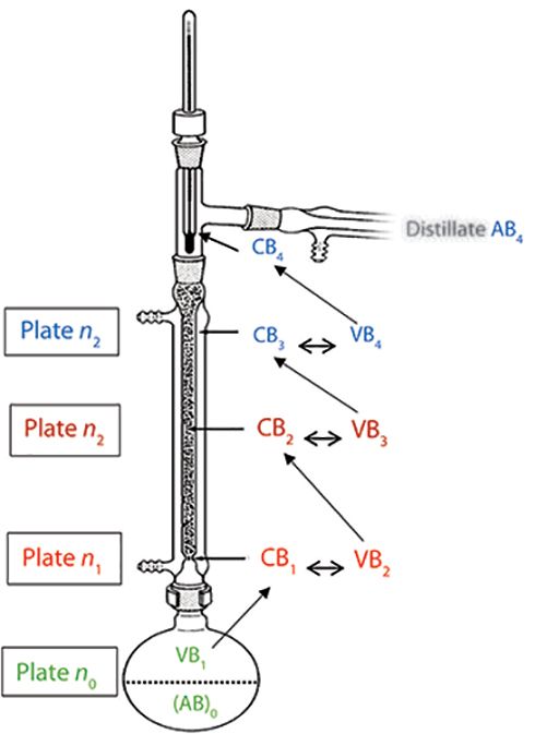
A more detailed explanation of the distillation process is as follows: We start with a binary mixture of components A and B, represented by (AB)0, in which B is the more volatile component. For simplicity, component A is not included in the notations; since mole fractions are implied, an increase of B represents a corresponding decrease of A. When heated to its boiling point, (AB)0 produces a vapor phase enriched in B, labeled VB1, in equilibrium with (AB)0.
As VB1 travels up a diathermic (that is, not insulated) fractionating column, it partially condenses to condensate CB1 when it reaches a cooler zone along the column. CB1, in the form of droplets, descends, until it reaches a zone with sufficient temperature to partially vaporize CB1 to VB2, a vapor phase containing a higher mole fraction of B. These vapors again rise to a cooler column zone, where they partially condense to form condensate CB2.
Droplets of CB2 fall to a sufficiently hot zone within the column, where they partially vaporize to form VB3, which is further enriched with B. Again, VB3 ascends the column, reaching a cooler zone, and partially condensing to CB3, whereby CB3 > CB2.
Vaporization and condensation continues throughout the distillation column as the vapor phase becomes more enriched in B, until VB4 is distilled, condensed as CB4, and collected. During distillation, the still pot composition becomes increasingly more enriched with component A.

Figure 1: Fractional distillation scheme of a 1:1 mole ratio mixture of liquids A and B, with B being the most volatile. In this example, the distillation column has three theoretical plates; the condensate and vapor that constitute the same plate number are coded with the same color. There is also an additional plate within the still pot, (AB)0 →VB1. If the column length is 1m, the “height” of each theoretical plate is 33 cm. During initial reflux of (AB)0, vapor phase VB1, enriched in B, condenses to CB1. The first theoretical plate within the column is condensate CB1 and VB2, with vapor enriched with B. As VB2 rises in the column, it condenses to CB2. As CB2 descends within the column, it partially volatilizes to VB3. The process is repeated using all available plates, until VB4 condenses to CB4, forming distillate AB4. Even though theoretical plates are viewed as physical regions within columns, there is not only considerable overlap, but plate locations change throughout a distillation.
The distillation schematic from the still pot to distillate AB4 is given in Figure 1 and summarized here, omitting notation A in vapor phase and condensate for clarity:
(AB)0 < VB1 = CB1 < VB2 = CB2 < VB3 = CB3 < VB4 = CB4 (distillate AB4 is formed)
The less-than sign indicates that the mole fraction of component B increases from left to right. Phases with the same subscripts indicate identical compositions. Pairs of phases with the same color code represent one theoretical plate. In this example, we have three theoretical plates within the column, and one within the still pot. Since there is no clear-cut demarcation within a column as to the location of plates, peak or zone broadening has no physical significance.
Laboratory distillation columns have several to perhaps a hundred theoretical plates, depending upon their length and design. Columns with increased surface areas have more plates, such as packed, Vigreux, or spinning band columns. It appears that the term "plate" originated from ledges or protuberances that were incorporated into distillation columns to serve as surfaces for vapor–condensate equilibria.
Distillation is complicated to model mathematically, since equilibrium conditions and vapor–condensate compositions are constantly changing during distillation. Nevertheless, empirical relationships have been developed, such as the Fenske equation, which relates the mole fraction ratio of components A and B in the distillate, YA and YB, to the still pot composition, XA and XB,

In this equation, n is the number of theoretical plates and α is the relative volatility ratio of components A and B,

VA and VB are the volatilities of the components, VA = yA/xA and VB = yB/xB, in which y is the mole fraction in the vapor phase, and x is the corresponding mole fraction in the liquid phase. (Theoretical plates in distillation is a different phenomenon than found in chromatography, thus n is used in equation 1, rather than N.)
The relative volatility of components is approximately proportional to the boiling point ratio of pure components. Thus, the separation of components with a large boiling point difference would require relatively few theoretical plates, whereas a large number of theoretical plates would be required for components with a small boiling point difference. Obviously, the required number of plates also depends upon the target purity of the distillate.
Fractional Distillation Applicability
Because fractional distillation is based on continuous equilibrium between vapor and liquid phases, it is not a chromatographic technique, but a separation process of low thermodynamic efficiency. Although the physical chemistry of vaporization–condensation was used to conceptualize plate theory, the procedure itself does not lend itself as an analytical technique, but remains as a widely used laboratory-scale method for purifying volatile compounds. Distillation also remains the dominant process for industrial separations of volatile components (4).
Distillation is best summarized by Primo Levi, a renowned Italian author and chemist who becomes transfixed as he watches over the purification of benzene using a Vigreux column, "of debatable efficiency" (5):
“Distilling is beautiful. First of all, because it is a slow, philosophic, and silent occupation, which keeps you busy but gives you time to think of other things, somewhat like riding a bike. Then, because it involves a metamorphosis from liquid to vapor, and from this once again to liquid; but in this double journey, up and down, purity is attained, an ambiguous and fascinating condition, which starts with chemistry and goes very far.”
Primo Levi, The Periodic Table
Countercurrent Extraction
In the mid-20th century, separation of solids was limited mostly to fractional crystallization, adsorption chromatography, and liquid–liquid extractions; the latter of which was the most popular. The chief drawbacks of extractions, however, were that they were performed individually in separatory funnels and lacked resolving power. To increase productivity and separation capability, a novel technique was developed based on sequential countercurrent extractions-the forerunner of modern LC.
In the 1940s, classical solvent–solvent extractions were automated so that multiple extractions of solutes could be performed simultaneously on a single sample. Most importantly, the method took advantage of small distribution constant differences among solutes in solution.
The approach was based on a process known as countercurrent distribution (CCD), and the most widely utilized system was developed by Lyman Craig. The Craig CCD device consists of a series of uniquely designed tubes with lower (L) and upper (U) compartments. The lower compartments are filled with the denser of the two immiscible liquid phases. The tubes are designed so that the lower liquid phase remains stationary, and the contents of the upper tube can be sequentially transferred from one upper tube to the next.
To simplify calculations, the bottom and top sections usually contain equal volumes. Depending on solubility, the sample is placed in either the first (n = 0) upper or lower tubes. Designations are n for the tube location or tube number, not the number of tubes, and r is the number of transfers or stages. The first upper and lower tubes are coded n = 0, and for the initial equilibrium (before the first transfer is made), r = 0.
Before a CCD run, the equilibrium constant K of the sample is established between the two immiscible liquid phases to obtain the solute fractions in the upper p and lower phases q,

in which p + q = 1 (see equation 5).
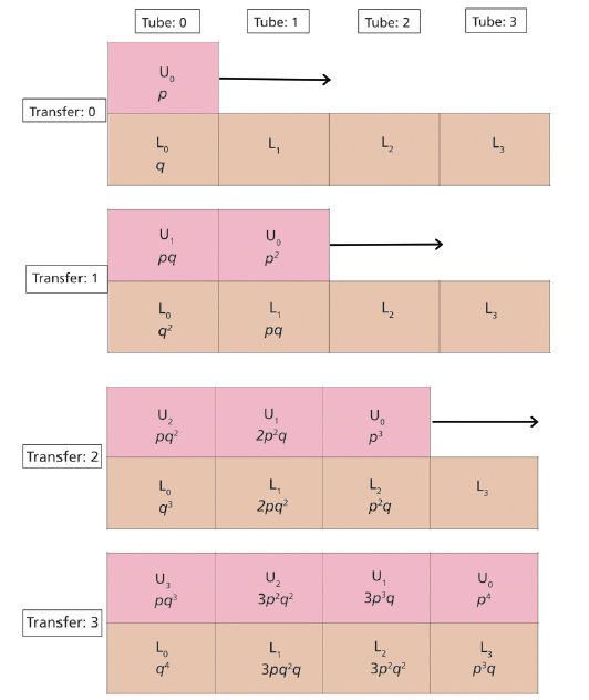
The first upper and lower tubes are assigned U0 and L0, the second set of tubes is U1 and L1, and so forth. The CCD process is shown schematically in Figure 2, for r = 3.

Figure 2: An example of a series of countercurrent extractions using three transfers ( r = 3) with three tubes ( n = 3), where U and L signify the upper and lower mobile and stationary phases, respectively, containing immiscible solvents. Not shown to the left of U0 is a series of three upper tubes, filled with equal volumes of lower-density, immiscible solvent. A. Initialization, r = 0: A sample is dissolved in either U0 or L0, depending upon its solubility. After the pair of tubes is shaken and contents settle, solute distribution is 1 as predicted from ( p + q )r = 0. B. First transfer, r = 1: The top row of tubes is moved one tube over to the right. After pairs U0/L1 and U1/L2 are shaken and the contents settle, the solute distribution is U0 = p 2, U1 = pq , L0 = q 2, L1 = pq as predicted from ( p + q ) r = 1. C. Second transfer, r = 2: The top row of tubes are moved one tube over to the right. After pairs U2/L0, U1/L1, and U0/L2 are shaken and contents settle, solute distribution is U0 = p 3, U1 = 2 p 2 q , U2 = pq , L0 = q 3, L1 = 2 p , L2 = p 2 q , as predicted from ( p + q ) r = 2.D. Third transfer, r = 3: The top row of tubes are moved one tube over to the right. After pairs U3/L0, U2/L1, U1/L2, and U0/L3 are shaken and contents settle, solute distribution is U0 = p 4, U1 = 3 p 3 q , U2 = 3 p 2 q2, U3 = pq , L0 = q 4, L1 = 3 pq , L2 = 3 q 2, L3 = p 3 q as predicted from ( p + q ) r = 3.
To begin the process, the sample is dissolved in either U0 or L0, the contents are shaken (or rotated in the case of Craig extraction tubes), and the contents are allowed to separate. The contents of U0 are then transferred or moved so that they are opposite to L1. The process is repeated until the requisite number of tubes are used. Typically, Craig CCD units may have hundreds of tubes.
The following procedures are used for the two initial transfers, or extractions:
A. The initial extraction: r = 0, U0 = p and L0 = q.
B. The first transfer r = 1: Shift upper bank of tubes to the right.
Upper tube 0 is opposite lower tube 1; upper tube 1 is opposite lower tube 0. After equilibration, solute content in upper and lower tubes is as follows: U0 = p2, U1 = pq, L0 = q2, L1 = pq.
C. The second transfer r = 2: Shift upper bank of tubes to the right.
Upper tube 0 is opposite lower tube 2, upper tube 1 is opposite lower tube 1, and upper tube 2 is opposite lower tube 0. After equilibration, solute content in upper and lower tubes is as follows: U0 = p3, U1 = 2p2q, U2 = pq2, L0 = q3, L1 = 2pq2, L2 = p2q.
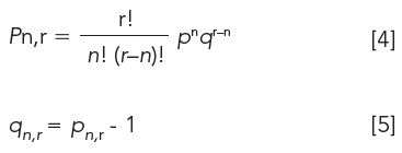
Solute distribution is governed by the binomial distribution, in which pn,r is the solute fraction in the upper phase and qn,r is the solute fraction in the lower phase:

If more tubes are added to a CCD separation, typically n > 20, the binomial distribution transforms into a Gaussian distribution:

After r transfers, the standard deviation of the resulting solute distribution is

In this format, σ is expressed in terms of the number of tubes. The width of a distribution obtained from a CCD run, which represents 98% of the CCD peak, is therefore

As one would expect, the larger the number of transfers r, the wider the distribution. Width of the CCD profile also depends upon the distribution coefficient of the sample. Samples with either high or low distribution coefficients give narrow peaks, with a maximum width obtained when p reaches 0.5.
The tube with the maximum amount of solute is

where µ is the tube location or the number of tubes at maximum concentration pn,r (µ increases with increasing transfers r). Obviously, the CCD apparatus must have the appropriate number of tubes to accommodate the transfers. Resolution between adjacent peaks also increases with r.
We now turn our attention to the number of theoretical plates in a CCD extraction. The number of theoretical plates N is the ratio of the square of retention time (or volume) to the peak variance σ2, in the corresponding units,

In CCD, solute properties are characterized in terms of the number of transfers r, not retention time. Because retention is t ∝ rp (equation 9) and peak width σ is equal to the square root of rpq (equation 7), equation 10 becomes

If the extraction volumes in the upper and lower phases are equal, the distribution coefficient K is equal to (see also equation 3),

where Cu and Cl are solute concentrations in the upper and lower phases, respectively. Because

then

and equation 11 is reduced to

Equation 15 indicates that the number of theoretical plates in a CCD run is equal to a fraction times the number of transfers or extractions. Since K = Cu/Cl = p/q, the more "time" a solute spends in the upper phase, the greater the plate number or CCD efficiency. If p = 1, the solute will remain in the first upper tube as it is transferred or transported, undiluted, to the last tube intact. If q = 1, the solute will be forever in Lo. These conditions would be chromatographically analogous to unretained and irreversibly retained analytes, respectively.
It should be mentioned that the number of transfers is equal to the number of extraction tubes, only if all the tubes are used. For example, a researcher may decide to use only use 500 transfers, even though his apparatus contains 1000 tubes. In this case, r = 500, not 1000, and his efficiency is reduced by 50%.
In distillation, HETP is defined as the minimum length of a column segment within which a solute is in equilibrium with upper and lower phases. With respect to CCD, HETP would be equal to n = 1, or the volume of one extraction tube.
Countercurrent Extraction Applicability
The Craig CCD apparatus has been supplanted by continuous or chromatographic modes of CCD in which one liquid phase is kept stationary by centrifugal forces and the other phase passes through it using rather ingenious mechanical methods (6–9).
One of the more successful designs is the coil planet centrifuge CCC (countercurrent chromatography) system, which uses a rotating helical coil of tubing. Other versions of CCC have been introduced, such as droplet CCC, centrifugal partition chromatography, high-speed CCC, and elution extrusion chromatography.
Because of their relatively low separation efficiency, CCD and associated techniques have been replaced with high performance liquid chromatography (HPLC) for analytical separations. CCD methods, however, are used mainly for semipreparative purification of compounds usually in complex matrices, rather than for analysis.
Conclusions
Before the development of chromatography, theoretical plates and the height equivalent to a theoretical plate were used to assess distillation efficacy. It was assumed that distillation occurred in discrete stages or plates along the length of the distillation column; the greater number of plates, the more efficient the distillation.
The plate concept was successfully carried over to CCD, which was the next separation technique to appear. Concentration profiles from CCD separations could be predicted using solute distribution coefficients and a Gaussian distribution model based on plate height theory. Furthermore, the extent of peak broadening and peak location, in terms of the number of transfers, could also be estimated.
From studies using the plate height model, the theory and practice of chromatography was realized by Martin and Synge, Nobel laureates. Their contributions, as well as Cal Giddings' singular approach to peak broadening, will be the subject of the next several installments of Chromatography Fundamentals.
References
(1) H.G. Barth, LCGC North Am. 36(3), 200–202 (2018).
(2) H.G. Barth, LCGC North Am. 36(6), 394–396, 405 (2018).
(3) H.G. Barth, LCGC North Am. 36(7), 472–473, 476 (2018).
(4) J. Pendergast, D. Jewell, D. Vickery, and J. Bravo, Chem. Process. 80(4), 16–21 (2018).
(5) P. Levi, The Periodic Table, trans. R. Rosenthal, Potassium Chapter (Schocken Books, New York, 1984).
(6) https://gfp.people.uic.edu/countercurrent/content/history
(7) J. Brent Friesen, J.B. McAlpine, S.-N. Chen, and G.F. Pauli, J. Nat. Prod. 78, 1765–1796 (2015).
(8) W.D. Conway and R.J. Petroski, Eds., Modern Countercurrent Chromatography, ACS Symposium Series 593 (American Chemical Society, Washington, DC, 1995).
Howard G. Barth is with Analytical Chemistry Consultants, Ltd., in Wilmington, Deleware. Direct correspondence to: howardbarth@gmail.com

In the present study, a gradient reversed-phase high-performance liquid chromatography (RP-HPLC) method has been designed and validated to quantify ornidazole (OZ) in the marketed formulation (oral gel) with the application of QbD.
A column with chemically modified column hardware showed improvements in analytical performance for siRNA compared to a conventional stainless-steel column.

.png&w=3840&q=75)

.png&w=3840&q=75)


.png&w=3840&q=75)


.png&w=3840&q=75)


