Chemometrical Experimental Design-Based Optimization Studies in Capillary Electrophoresis Applications
LCGC North America
A synopsis of our work detailing the use of chemometric response surface methodology (RSM) in two capillary electrophoresis (CE) studies is described.
Capillary electrophoresis (CE) is a powerful separation technique that has gained widespread use in biological laboratories because of its versatility and ease of use (1–11). It is an excellent tool for many types of bioanalyses and is an unparalleled experimental tool for biophysical studies of interactions in biologically relevant media. Separations are based upon the principles of the electrically driven flow of ions in solution. Selectivity can be manipulated by the alteration of electrolyte properties such as pH, ionic strength, and electrolyte composition, or by the incorporation of electrolyte additives.

Two techniques that have proven to be quite valuable in analyzing the physicochemical properties of biological species are affinity capillary electrophoresis (ACE) and electrophoretically mediated microanalysis (EMMA). For almost 20 years ACE has been used successfully to estimate binding parameters between ligands and receptors (12–30). Since the first papers in 1992 (12–15) documenting its use in measuring affinity parameters between biological species, its use in probing a variety of receptor–ligand interactions has greatly expanded and includes, but is not limited to, protein–drug, protein–DNA, peptide–peptide, peptide–carbohydrate, carbohydrate–drug, and antibody–antigen interactions (12–30). ACE uses the resolving power of CE to distinguish between free and bound forms of a receptor as a function of the concentration of free ligand in the electrophoresis buffer. In a typical form of ACE a sample of receptor and standard or standards is exposed to an increasing concentration of ligand in the running buffer causing a shift in the migration time of the receptor relative to the standards. In EMMA, differential electrophoretic mobility is utilized to merge distinct zones of analyte and analytical reagents under the influence of an electric field. The reaction is then allowed to proceed within the region of reagent overlap either in the presence or absence of an applied potential, and the resultant product is transported to the detector under the influence of an electric field (31–46). Many studies have detailed the use of EMMA in examining myriad enzyme systems resulting in the development of an excellent complement to traditional biological assay techniques.

Figure 1: (a) Whole model leverage plot of actual vs. predicted responses and (b) model generated contour plots showing injection time versus capillary length. (Reprinted with permission from reference 61.)
CE has a number of weaknesses as an analytical technique including adsorption of charged species onto the capillary wall and Joule heating that can cause variances in electroosmotic flow (EOF) and, hence, irreproducibility in the peak migration times of the analytes under study. These disadvantages have been a major reason CE has yet been fully integrated into many more analytical laboratories.
A number of multivariate chemometric-based techniques including response surface methodology (RSM) have been developed to aid in the optimization of a given system's performance. The use of chemometrics in high performance liquid chromatography (HPLC), mass spectrometry (MS), atomic absorption (AA), and other techniques is well-documented (47–51). Because CE and its applications are more universally known, this article will focus on the basics of chemometrics and its use in two specific applications from our laboratories: flow-through partial filling ACE (FTPFACE) and EMMA.
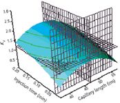
Figure 2: Response surface generated plot showing main interaction injection time vs. capillary length. (Reprinted with permission from reference 61.)
Discussion on Chemometrics
In chemometrics, the main applications of experimental design include factor screening, response surface examination, system optimization and system robustness. The implementation of these procedures requires the following steps:
- Determine the overall goals and objectives of the experiment;
- Define the overall outcome (response) of the experiment;
- Define the factors (and their levels) that will influence the response; and
- Choose a design that is compatible with the overall objectives, number of factors considered, and required precision of measurements.
This approach is contrary to the classical univariate method in which the response is investigated for each factor while all other factors are held at a constant level. Univariate methods are time-consuming and do not take interactive effects between factors into account (52). If the effects are additive in nature, then experimental designs are the optimum choice and require fewer measurements.
Blocking is a fundamental principle of good experimental design and is employed when extraneous sources of variation that influence the response are known. The blocking process reduces the variability from the most important sources and increases the precision of experimental measurements. Here, experimental units are grouped into homogeneous clusters to improve the comparison of treatments by randomly allocating the treatments within each cluster or "block." Randomization can then used to reduce the variability from the remaining extraneous sources. Analysts also can employ the processes of replication and repetition for each factor combination, to allow a better estimate of experimental error, which helps determine whether observed differences in the data set are truly statistically different. Replication also allows an estimation of the true mean response for one or more factor levels, thus, aiding in precisely defining the effect of a factor on the response (53).

Figure 3: A representative set of electropherograms of CAB (darkened circle) in 192 mM glycineâ25 mM Tris buffer (pH 8.3) containing various concentrations of 1 using the FTPFACE technique. The total analysis time in each experiment was 7.0 min at 11 kV (current 2.8 μA) using a 47-cm (inlet to detector), 50-μm i.d. open, uncoated quartz capillary. MO (open square) and horse heart myoglobin (HHM) (open circle) were used as internal standards. The asterisk (*) and cross (+) are discussed in the text. (Reprinted with permission from reference 61.)
Screening techniques such as factorial designs allow the analyst to select which factors are significant and at what levels. The most general (two level design) is a full factorial design and described as 2k-designs where the base 2 stands for the number of factor levels and k the number of factors each with a high and low value (54–58). The lower level is indicated with a "-" sign; the higher level with a "+" sign. The combination of two factor levels is termed a treatment or run. With two factors a square is defined in the factor space and with three factors a cube is defined. Fractional factorial designs are good alternatives to a full factorial design, especially in the initial stage of a project, and considered a representative subset of a full factorial design (55). In fractional factorial designs, the number of experiments is reduced by a number p according to a 2 k- pdesign.

Table I: Experimental factors and levels used in the BoxâBehnken design. (Reprinted with permission from reference 61.)
RSMs are multivariate techniques that mathematically fit the experimental domain studied in the theoretical design through a response function (54,58). Two of the most common designs generally used in response surface modeling of CE applications are central composite and Box–Behnken designs. Central composite designs contain imbedded factorial or fractional factorial designs with center points that are augmented with a group of axial (star) points that allow estimation of curvature (54,58). A central composite design always contains twice as many star points as there are factors in the design. The star points then represent new extreme values ("-" and "+") for each factor in the design.
The Box–Behnken design is considered an efficient option in RSM and an ideal alternative to central composite designs (54). It has three levels per factor, but avoids the corners of the space, and fills in the combinations of center and extreme levels. It combines a fractional factorial with incomplete block designs in such a way as to avoid the extreme vertices and to present an approximately rotatable design with only three levels per factor. This design is appropriate for situations where the experimenter is not interested in predicting response at extremes. A less common, but effective method is the Doehlert design. Like the Box–Behnken design, Doehlert designs require lower numbers of experiments than the central composite design (59–61). Another advantage of the Doehlert design over the central composite approach is its higher efficiency value, ultimately determined by dividing the coefficient number of the quadratic equation by the number of experiments required for the design.
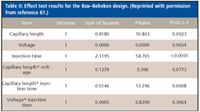
Table II: Effect test results for the BoxâBehnken design. (Reprinted with permission from reference 61.)
Results and Discussion
FTPFACE: In the first study we used chemometrics RSM to predict extent of protein–ligand binding in flow through partial filling ACE (FTPFACE) (62). Here, the value for Kd was estimated using one non-interacting standard which relates changes in the electrophoretic mobility of carbonic anhydrase B (CAB, E.C.4.2.1.1) on complexation with 4-carboxybenzenesulfon-amide (CBSA) ( 1) present in the electrophoresis buffer. Experimental factors including injection time, capillary length and applied voltage were selected and tested at three levels in a Box–Behnken design. Statistical analysis results were used to create a mathematical model for response surface prediction via contour and surface plots at a given target response of Kd = 1.19 × 10⁻⁶ M. The adequacy of the model was validated by experimental runs with the predicted model solution (capillary length = 47 cm, voltage = 11 kV, injection time = 0.01 min).
The design matrix (including actual and model predicted responses) generated for the Box–Behnken study is shown in Table I. Here, three center point experiments were incorporated to compute an estimate of the error term that does not depend upon the fitted model. Figure 1a shows the whole model leverage plot of actual versus predicted responses (based upon all effects) with the quality of fit expressed by the coefficient of determination (r2). This coefficient is variation in the response around the mean that can be attributed to terms in the model rather than to random error.
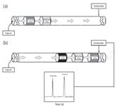
Figure 4: Schematic representation of an in-capillary enzyme-catalyzed microreactor (a) before reaction and (b) after reaction. (Reprinted with permission from reference 62.)
Typically, points on the leverage plot are actual data coordinates and the horizontal line the sample mean of the response. Here we have multiple effects, with the horizontal line representing a partially constrained model instead of a model fully constrained to a single mean value. As shown, the confidence curves (dashed lines) cross the horizontal line, thus, the test is considered significant at the 5% level. Overall, an r2 value of 0.89 was obtained with a mean response of 1.57. Analysis of variance (ANOVA) for a linear regression partitions the total variation of a sample into components. Effect tests results (Table II) revealed that injection time and capillary length had significant single effects on the target response. The only significant interactive effect was capillary length*injection time. Here, P>F is the significance probability for the F-ratio.
Figure 1b shows the contour profiles of injection time versus capillary length. Two others (not shown) include voltage vs. capillary length and voltage vs. injection time. Here, we have assessed how the predicted values change with respect to changing each factor, two at a time. As before, a target value of Kd = 1.19 × 10⁻⁶ M was set and the adjusted response surface glider moved along the axes of each combination of factors until the levels of factors reached the target response. As expected, there were a number of predicted solutions that reached our target response based upon the significance of each factor at appropriate levels. This is very important in situations where one or more factors cannot be varied at a large range of levels (as in the case of capillary length in the previously mentioned studies). Here, we were limited to set capillary lengths of 37, 47, and 57 cm due to the nature of the commercial instrument setup.
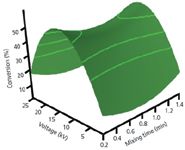
Figure 5: Response surface image for the main interactive effect of voltageâmixing time at predicted critical values with enzyme concentration kept constant. (Reprinted with permission from reference 62.)
Representative resolution response surfaces in function of one of the chosen factors and levels (from the contour plot analysis) which reached our predicted response are depicted in Figure 2. Here, a control changes to a drop-down list of predefined resolutions for density grids in the JMP software. Too coarse a resolution means a function with a sharp change might not be represented as well, but setting the resolution high makes evaluating and displaying the surface slower. Grids parallel to each axis were generated to further enhance the response surface effects for interpretation purposes.
The generated model was validated experimentally by a representative series of electropherograms of CAB in capillaries partially filled with increasing concentrations of (0–25 mM) of 1 run at optimized conditions (Figure 3). CAB is a zinc protein of the lyase class that catalyzes the equilibration of dissolved carbon dioxide and carbonic acid. It is strongly inhibited by sulfonamide-containing molecules.
At the point of detection, separate peaks for CAB, HHM, and mesityl oxide (MO) are observed.The complex that forms between CAB and 1 is more negatively charged than CAB uncomplexed and, hence, the peak for the complex shifts to longer migration time on increasing the concentration of 1 partially filled in the capillary column. A fourth peak (designated with an asterisk) appears under the original CAB peak and is designated as inactive CAB a result of using an older sample of CAB in some of our studies. This inactive CAB does not effect the measurement of a binding constant. The zone of ligand, typically seen in FTPFACE when the ligand is chromophoric, was observed after the maximal value of the x axis shown in Figure 3. CAA(+) is an isozyme of CAB and gives values of Kd indistinguishable from CAB. A binding constant of 1.29 × 10⁻⁶ M was obtained, an 8.4% discrepancy difference from the target response (1.19 × 10⁻⁶ M).
EMMA: In a second study, we used RSM in EMMA by examining the optimization of reaction conditions for the conversion of nicotinamide adenine dinucleotide (NAD) to nicotinamide adenine dinucleotide, reduced form (NADH) by glucose-6-phosphate dehydrogenase (G6PDH, EC 1.1.1.49) in the conversion of glucose-6-phosphate (G6P) to 6-phosphogluconate (63). Experimental factors including voltage (V), enzyme concentration (E) and mixing time of reaction (M) at the applied voltage were selected at three levels and tested in a Box–Behnken response surface design. Upon migration in a capillary under CE conditions, plugs of substrate and enzyme are injected separately in buffer and allowed to react at variable conditions (Figure 4). Extent of reaction and product ratios were subsequently determined by CE. The model predicted results are shown to be in good agreement (7.1% discrepancy difference) with experimental data.
Table III shows the three electrophoretic factors and levels selected in which experimental optimization, in terms of overall response (% conversion), could be performed. A design matrix was then generated for the Box–Behnken study (Table IV). It was found that voltage and mixing time, when combined, had a significant effect on %conversion. Here, the extent of contact between substrate and enzyme is dictated by the difference in electrophoretic mobilities, which is in turn dictated by mixing time and voltage. Such an interaction would not have been possible by use of classical univariate optimization methods.

Table III: Experimental factors and levels used in the BoxâBehnken design. (Reprinted with permission from reference 62.)
The quadratic model from the Box–Behnken design allowed us to generate a response surface image (Figure 5) for the main interaction voltage and mixing time. Here, we assessed how the predicted responses change with respect to changing these factors simultaneously, while keeping enzyme concentration constant. A post-hoc review of our model revealed optimum critical values of: mixing time = 0.78 min, voltage = 13.2 kV, enzyme concentration = 2.82 mg/mL and a predicted conversion of 31.2%. A series of five validation experiments using the optimum critical values were performed. A mean experimental conversion of 29.0% was obtained with a 7.1% discrepancy difference from the model predicted. The generated model was validated experimentally by a representative electropherogram (Figure 6) showing the separation of NAD and NADH after reaction with G6PDH.

Table IV: Box-Behnken design matrix with mean predicted and experimental responses. (Reprinted with permission from ref. 62.)
Conclusion
The need to assess many compounds expeditiously and accurately via high-throughput techniques including CE has made experimental optimization more important than at any time in history. Chemometrical experimental design and optimization techniques in CE have been instrumental in separating multicomponent environmental samples, DNA fragments, soluble organic acids and chiral molecules that otherwise proved troublesome. We have described two applications (FTPFACE and EMMA) in CE that have benefited from chemometrics. It can be concluded that this approach yielded a large amount of information while minimizing the number of experimental runs. Such an approach is having significant impacts in separation science and will no doubt be a major area of study for years to come. This work provides further basis for integrating chemometrics in CE and especially in applications where optimizing experimental conditions are time-consuming, require large amounts of expensive reagents and/or where a univariate approach to optimization yields results of marginal confidence and accuracy.
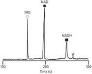
Figure 6: Representative electropherogram showing the separation of NAD and NADH after reaction with G6PDH in 30 mM Tris buffer (pH 7.85). The total analysis time in this experiment was 8.0 min at 13.2 kV (current 22.8 μA) using a 40.5-cm (inlet to detector), uncoated capillary. MO was used as an internal standard. The peak marked * is an impurity. (Reprinted with permission from reference 62.)
Acknowledgments
The authors gratefully acknowledge financial support for this research by grants from the National Science Foundation (CHE-0515363 and DMR-0351848), and the National Institutes of Health (1R15AI65468-01).
References
(1) L. Clohs and K.M. McErlane, J. Pharm. Biomed. Analysis 24, 545–554 (2001).
(2) N.A. Guzman, Anal. Bioanal. Chem. 378, 37–39 (2004).
(3) C.L. Flurer, Electrophoresis 22, 4249–4261 (2001).
(4) W. Thormann, R. Theurillat, M. Wind, and R. Kuldvee, J. Chromatogr. A 924, 429–437 (2001).
(5) L.K. Amundsen and H. Siren, Electrophoresis 28, 99–113 (2007).
(6) V. Villareal, Y. Zhang, C. Zurita, J. Moran, I. Silva, and F.A. Gomez, Anal. Letters 36, 451–463 (2003).
(7) M.V. Novotny, M. Hong, A. Cassely, and A. Mechref, J. Chromatogr. A 752, 207–213 (2001).
(8) B.M. Busby and G. Vigh, Electrophoresis 26, 3849–3860 (2005).
(9) J. Simal-Gándara, Crit. Rev. Anal. Chem. 34, 85–94 (2004).
(10) J.P. Landers, Handbook of Capillary Electrophoresis (CRC Press LLC, Boca Raton, Florida, 1997).
(11) V. Villareal, J. Kaddis, M. Azad, C. Zurita, I. Silva, L. Hernandez, M. Rudolph, J. Moran, and F.A. Gomez, Anal. Bioanal. Chem. 376, 822–831 (2003).
(12) J.C. Kraak, S. Bush, and H. Poppe, J. Chromatogr. 608, 257–264 (1992).
(13) Y.-H Chu and G.M. Whitesides, J. Org. Chem. 57, 3524–3525 (1992).
(14) N.H.H. Heegaard and F.A. Robey, Anal. Chem. 64, 2479–2482 (1992).
(15) Y.-H Chu, L.Z. Avila, H.A. Biebuyck, and G.M. Whitesides, J. Med. Chem. 35, 2915–2917 (1992).
(16)F.A. Gomez, J.N. Mirkovich, V.M. Dominguez, K.W. Liu, and D.M. Macias, J. Chromatogr. A 727, 291-299 (1996).
(17) K.L. Rundlett and D.W. Armstrong, Electrophoresis 18, 2194–2202 (1997).
(18) X.-H Qian and K.B. Tomer, Electrophoresis 19, 415-419 (1998).
(19) J.J. Colton, J.D. Carbeck, J. Rao and G.M. Whitesides, Electrophoresis 19, 367–382 (1998).
(20) J. Heintz, M. Hernandez, and F.A. Gomez, J. Chromatogr. A 840, 261–268 (1999).
(21) E. Mito, Y. Zhang, S. Esquivel, F.A. Gomez, Anal. Biochem. 280, 209–215 (2000).
(22) A. Varenne, P. Gareil, S. Colliec-Jouault, and R. Daniel, Anal. Biochem. 315, 152–159 (2003).
(23) D.D. Buchanan, E.E. Jameson, J. Perlette, A. Malik, and R.T. Kennedy, Electrophoresis 24, 1375–1382 (2004).
(24) A. Taga, Y. Yamamoto, R. Maruyama, and S. Honda, Electrophoresis 25, 876–881 (2004).
(25) M. Castagnola, D.V. Rossetti, R. Inzitari, A. Lupi, C. Zuppi, T. Cabras, M.B. Fadda, G. Onnis, R. Petruzzelli, B. Giardina, and I. Messana, Electrophoresis 25, 846–852 (2004).
(26) M. Azad, A. Brown, I. Silva, and F.A. Gomez, Anal. Bioanal. Chem. 379, 149–155 (2004).
(27) Y. Zhang, C. Kodama, C. Zurita, and F.A. Gomez, J. Chromatogr. A, 928, 233–241 (2001).
(28) E. Mito and F.A. Gomez, Chromatographia 50, 689–694 (1999).
(29) M. Azad, L. Hernandez, A. Plazas, M. Rudolph, and F.A. Gomez, Chromatographia 57, 339–347 (2003).
(30) Y. Zhang, F.A. Gomez, J. Chromatogr. A 897, 339–347 (2000).
(31) B.J. Harmon, D.H. Patterson, and F.E. Regnier, Anal. Chem. 65, 2655–2662 (1993).
(32) D.H. Patterson, B.J. Harmon, and F.E. Regnier, J. Chromatogr. A 662, 389–394 (1994).
(33) D.H. Patterson, B.J. Harmon and F.E. Regnier, J. Chromatogr. A 732, 119–132 (1996).
(34) D.S. Zhao and F.A. Gomez, Electrophoresis 19, 420–426 (1998).
(35) D.S. Zhao and F.A. Gomez, Chromatographia 44, 514–520 (1997).
(36) E.-S Kwak, S. Esquivel, and F.A. Gomez, Anal. Chim. Acta 397, 183–190 (1999).
(37) Y. Zhang, R. El-Maghrabi, and F.A. Gomez, Analyst 125, 685–689 (2000).
(38) L.Z Avila and G.M. Whitesides, J. Org. Chem. 58, 5508–5512 (1993).
(39) S. Van Dyck, A. Van Schepdael, and J. Hoogmartens, Electrophoresis 23, 2854–2859 (2002).
(40) A.R. Whisnant, S.E. Johnston, and S.D. Gilman, Electrophoresis 21, 1341–1348 (2000).
(41) Q. Xue and E. Yeung, Nature 373, 681–683 (1995).
(42) B.J Burke and F.E. Regnier, Anal. Chem. 75, 1786–1791 (2003).
(43) Z. Glatz, J. Chromatogr. A 841, 23–28 (2006).
(44) L.M. Lewis, L.J. Engle, W.E. Pierceall, D.E. Hughes, and K.J. Shaw, J. Biomol. Screen. 9, 303–308 (2004).
(45) A. Brown, R. Desharnais, B.C. Roy, S. Mallik, and F.A. Gomez, Anal. Chim. Acta 540, 403–409 (2005).
(46) G. Li, X. Zhou, Y. Wang, A. El-Shafey, N.H. Chiu, I.S. Krull, J. Chromatogr. A 1053, 253–263 (2004).
(47) E. Dinc, A. Ozdemir, H. Aksoy, O. Ustundag, and D. Baleanu, Chem. Pharm. Bull. 54, 415–421 (2006).
(48) P.C. Damiani, M.D.B. Orraccetti, and A.C. Olivieri, Anal. Chim. Acta, 471, 87–96 (2002).
(49) A.A.S.G. Lonni, I.S. Scarminio, L.M.C. Silva, and D.T. Ferreira, Anal. Sci. 19, 1013–1017 (2003).
(50) A. Duarte and S. Capelo, J. Liq. Chromatogr. Rel. Tech. 29 1143–1176 (2006).
(51) F. Xu, F. Gong, S.J. Dixon, R.G. Brereton, H.A. Soini, M. V. Novotny, E. Oberzaucher, K. Grammer, and D.J. Penn. Anal. Chem. 79, 5633–5641 (2007).
(52) P.W. Araujo and R.G. Brereton, Trends Anal. Chem. 15, 63–70 (1996).
(53) D.C. Montgomery. Design and Analysis of Experiments, 6th Edition (John Wiley & Sons, New York, 2005).
(54) S.D. Brown and R.S. Bear, Crit. Rev. Anal. Chem. 24, 99–131 (1993).
(55) T. Lundstedt, E. Seifert, L. Abramo, B. Thelin, A. Nyström, J. Pettersen, and R. Bergman, Chemo. Intell. Lab Systems 42, 3–40 (1998).
(56) M. Otto, Chemometrics: Statistics and Computer Applications in Analytical Chemistry (Wiley-VCH, Chichester, UK, 1999).
(57) R.E. Bruns, I.S. Scarminio, and B. de Barros Neto, Statistical Design — Chemometrics (Elsevier, Amsterdam, 2006).
(58) G.E.P. Box, W.G. Hunter, and J.S. Hunter, Statistics for Experimenters: An Introduction to Design, Data Analysis and Model Building (Wiley, New York, 1997).
(59) S.L.C. Ferreira, W.N.L. dos Santos, C.M. Quintella, B.B. Neto, and J.M. Bosque-Sendra. Taltanta 63, 1061–1067 (2004).
(60) J. Gabrielsson, N.-O. Lindberg, and T. Lundstedt, J.Chemometrics 16, 141–160 (2002).
(61) J.A. de Azeredo Amaro and S.L.C. Ferreira. J. Anal. At. Spectrom. 19, 246–249 (2004).
(62) G. Hanrahan, R.E. Montes, A. Pao, A. Johnson, and F.A. Gomez, Electrophoresis 28, 2853–2860 (2007).
(63) R.E. Montes, F.A. Gomez and G. Hanrahan, Electrophoresis 29, 375–380 (2008).

Removing Double-Stranded RNA Impurities Using Chromatography
April 8th 2025Researchers from Agency for Science, Technology and Research in Singapore recently published a review article exploring how chromatography can be used to remove double-stranded RNA impurities during mRNA therapeutics production.


