The Bermuda Triangle
LCGC North America
When is it time to throw in the towel?
We've all read stories about the famous Bermuda Triangle, a region of the Atlantic Ocean near Bermuda where unexplained forces cause ships to sink and planes to disappear off the radar. Sometimes it seems like the same forces inhabit our laboratories. Over the past week, I've had a series of e-mail exchanges with a reader named John (not me) regarding a particularly vexing problem with his liquid chromatograph. His final note contained this sentence: "If you are looking for something to write articles on, you should do one on knowing when it is time to throw in the towel and blame the problem on the Bermuda Triangle; I am now convinced that [my laboratory] is located at its dead center." It is true that we never found a definitive cause for the problem, although we suspect its source strongly. However, the troubleshooting process John used was so thorough that it serves as an excellent case study on how to go about isolating a problem. Yes, this is a true story — I've changed only a few details to disguise the brand of equipment used.

John W. Dolan
The Problem
The liquid chromatography (LC) system used comprising a low-pressure mixing pump with four-solvent capability, an in-line vacuum degassing system, an autosampler, a column heater, and internal electronics. A variable-wavelength UV detector from the same manufacturer was used. System control and data acquisition were done via personal computer with software supplied by the system vendor. Two different methods were used. One method used two size-exclusion chromatography (SEC) columns in series operated at room temperature, a 0.5 M sodium sulfate mobile phase, a flow rate of 0.55 mL/min, and a detection wavelength of 206 nm. The second method was reversed phase with a C18 column operated at 35 °C, a mobile phase of 5 mM acetate buffer (pH 4.4)–acetonitrile blended on-line, a flow rate of 1.5 mL/min, and a detection wavelength of 258 nm.
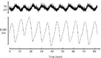
Both methods experienced the problem of baseline noise. The noise appeared as a nearly perfect sine wave with a period of approximately 7 min. The period changed slightly from day to day but was very consistent over the course of a single day. When the baseline noise was first noticed, John began monitoring the system pressure output from the controller and noticed the noise on this channel as well. An overlay of the pressure and baseline plots showed that the noise had the same period on both, but was 180° out of phase (see Figure 1). The troubleshooting process described here took place over more than a month.

Figure 1: Cyclic noise problem. (Top) Pressure monitor and (bottom) UV detector output. See text for details.
Check the Obvious
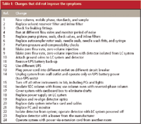
When LC problems are encountered, one of the first questions many users ask is whether the problem is related to the system or the method. One would like to be able to make a simple test that would answer that question. I generally recommend taking the "divide and conquer" technique (for example, see reference 1), in which experiments are made that help eliminate large portions of the system or method from suspicion. John chose to do this by replacing the columns, mobile phases, standards, and samples and rerunning both methods. This had no effect on the problem, as noted in Table I.1 (this and other experiments are summarized in Tables I and II, with the line referenced in the table appended to the table number in the text). Because both methods continued to show problems, this points us toward the system as being the problem source, not the method.

Table I: Changes that did not improve the symptoms
When the problem source isn't obvious, sometimes it is easiest to perform some simple system maintenance tasks first, because they take little effort, might need to done anyway, and "can't hurt." John replaced the solvent reservoir inlet line frits and the in-line filter between the autosampler and column (Table I.2) with no improvement. A thorough check of the system for leaks was made (Table I.3), and no leaks were found.
Periodic baseline fluctuations, especially when accompanied by similar pressure fluctuations, make one suspect that an air bubble might be present or some other pump malfunction is taking place. A change of the flow rate should be reflected in a change in the period of the noise if this is the case, but the flow rate did not correlate with the noise (Table I.4).
Once these simple checks had been made, John began to perform some more serious maintenance. The LC pump was serviced, including replacement of the pistons, piston seals, check valves, and in-line filters (Table I.5), but no improvement was seen. A similar service procedure was performed on the autosampler, with replacement of all service parts (Table I.6), to no avail. Just to be sure that the pump and autosampler service didn't introduce any problems, a pump pressure test and solvent compressibility test were performed, but all tests passed (Table I.7).
If the pump and autosampler were working correctly, it didn't seem like these components were the problem source. However, a couple of additional checks were made just in case. First, the flow rate was set to zero and then the injection volume was set to zero. For this brand of system, these settings allow the electronic program to run, but the pump does not operate and the injection valve does not rotate. The noise persisted (Table I.8). As a further test, the detector inlet line was disconnected and the inlet and outlet were looped together so that no solvent flowed through the detector. The zero flow–zero volume injection was repeated, but the noise remained (Table I.9).
The tests and service procedures performed to this point were based upon the assumption that the problem was related to a physical defect in the system. The test results made John fairly confident that the pump, autosampler, and mobile phase delivery portion of the system were working properly.
Electrical Issues?
When the noise problem persisted with the detector disconnected (Table I.10), John began to suspect electrical problems were the source of the noise. Improper electrical grounding can cause strange symptoms, so he added ground wires to the LC system and detector and grounded them to a common ground source (Table I.10). No change was observed.
The lab normally ran all instruments on uninterruptible power supplies (UPS) to help protect against data loss in case of power outages and to protect against power surges. John removed the UPS unit to see if it was defective, but no improvement was made (Table I.11). Replacement of the UPS with a new unit did not correct the problem either (Table I.12). He thought there might be something wrong with the electrical circuit, because three other LC systems in the lab were working properly. The problem unit was unplugged and moved to a circuit that had worked well for one of the other LC systems, but no improvement was noted (Table I.13). As an extra check of power problems, the system was operated only on the battery power from the UPS. One UPS was used for the LC system and a second UPS for the detector, but neither was plugged into the wall. Still no improvement occurred (Table I.14).
Could the other instruments in the lab be causing the problem? All the analytical instruments and computers were unplugged. Even the lights were turned out, but the baseline noise persisted (Table I.15).
Although modern UV detectors have heat exchangers that help protect against temperature fluctuations, they still can respond when the refractive index of the mobile phase changes due to temperature changes. The most common source of temperature fluctuation is poor column temperature control. The reversed-phase method normally was operated with the column heater on. A foam insulating jacket was wrapped around the SEC columns, which were too big to fit in the column oven, to protect them from temperature changes; no improvement was seen (Table I.16). Another common source of such temperature cycling can be a heating duct that blows on the detector. To check for this, John placed a large cardboard box over the system to protect it from drafts, but the cycling noise remained (Table I.17).
Next, a series of more drastic service measures was undertaken. In a sequential manner, the power supply of the LC system was replaced (Table I), the optical components of the detector were replaced and realigned (Table I.19), the interface card for the data system and all the data system cables were replaced (Table I.20), and the computer was replaced (Table I.21). None of these changed improved things. The noise persisted even with the LC system powered off and only the detector on (Table I.22). Just to make sure something wasn't overlooked, John arranged to get another nominally identical detector on loan from the manufacturer. This did not fix the problem, either (Table I.23).
Move Elsewhere
With the long string of failures, John was beginning to wonder if he had made the proper initial diagnosis that the problem was related to the instrument and not the method. So he set up the method on a nominally identical system in the research and development lab in another building. The problem was gone (Table II.1)! Finally, a solution seemed possible. He then removed the detector from the problem system and set it up on the R&D system. It worked properly (Table II.2). This suggested that the problem might be with the location of the detector, not the detector itself.

Table II: Changes that Did Improve the Symptoms
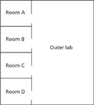
To further explore the possibility that the location of the system was the problem, John put the system on a laboratory cart and moved it to various locations within the lab (Table II.3). The original location was in a 20 × 20 ft room (Figure 2, room B). When the cart was moved to the far wall of the outer lab, the noise was no longer present. It also was absent in room D. The cycle time of the noise in room C was about half that in room B, and in room A the cycle was twice as fast. As one last test, John ran a long extension cord from the far side of the outer lab, where the system had worked properly, and used it to power the system in its normal location in room B. The problem was back (Table I.24). John was beginning to think that it was time for a long vacation or a transfer to another department!

Figure 2: Laboratory layout.
Gremlins?
It was clear that something associated with rooms A, B, and C that was the source of the problem. John checked each room and adjoining laboratories for equipment that could be a large power consumer, such as centrifuges, water baths, ovens, NMR instruments, and other large equipment. Nothing could be found anywhere near the problem labs. In his searches, John popped out a ceiling tile in room A and looked into the space above the ceiling. He discovered the HEPA air filtration unit that serviced the entire building. Such a large unit must have an automatic cleaning mechanism and likely an electrostatic dust filter as well. We suspect that this is the source of the problem, but there is no way to shut down the system for testing without closing down a production line in another part of the building, so the question will have to go unanswered.
Conclusions
This is one of those problems that is encountered sometimes, for which there is no satisfying solution. It is puzzling why the other LC systems in the same room operated properly and why just this one brand and model was susceptible to the electrical noise we presume was induced by the HEPA filter. The problem serves as a very good example of how to troubleshoot a difficult problem in a step-by-step manner. A lot of time was invested in an effort to find the solution, and many of us would have given up much sooner. John discovered his lab's Bermuda Triangle and decided to switch rather than fight — he's moving the LC system to another lab. I think John deserves the LC Troubleshooting Medal of Honor for troubleshooting efforts above and beyond the call of duty!
References
(1) J.W. Dolan,
LCGC
22
(7), 618–622 (2004).
John W. Dolan"LC Troubleshooting" Editor John W. Dolan is Vice-President of BASi Northwest Laboratory of McMinnville, Oregon; a Principal Instructor for LC Resources, Walnut Creek, California; and a member of LCGC's editorial advisory board. Direct correspondence about this column to "LC Troubleshooting," LCGC, Woodbridge Corporate Plaza, 485 Route 1 South, Building F, First Floor, Iselin, NJ 08830, e-mail John.Dolan@Bioanalytical.com.
For an ongoing discussion of LC trouble-shooting with John Dolan and other chromatographers, visit the Chromatography Forum discussion group at http://www.chromforum.com.

Common Challenges in Nitrosamine Analysis: An LCGC International Peer Exchange
April 15th 2025A recent roundtable discussion featuring Aloka Srinivasan of Raaha, Mayank Bhanti of the United States Pharmacopeia (USP), and Amber Burch of Purisys discussed the challenges surrounding nitrosamine analysis in pharmaceuticals.
Extracting Estrogenic Hormones Using Rotating Disk and Modified Clays
April 14th 2025University of Caldas and University of Chile researchers extracted estrogenic hormones from wastewater samples using rotating disk sorption extraction. After extraction, the concentrated analytes were measured using liquid chromatography coupled with photodiode array detection (HPLC-PDA).


