A Look at Vacuum-Jacketed Columns: Maximum Efficiency, Easy Deployment Without Oven, and Improved LC–MS Performance
Special Issues
The design of a user-friendly vacuum-jacketed column (VJC) is described for improved LC–MS performance, which does not require a large vacuum chamber with multiple vacuum pumps. Using this configuration, the experimental peak capacities measured for a 2.1 mm × 100 mm column packed with sub-2-μm particles and placed in the VJC-MS probe are doubled with respect to standard LC–MS systems.
This article demonstrates how a user-friendly vacuum-jacketed column (VJC) has been designed without the need of a large internal diameter vacuum chamber and low- and high-vacuum pumps. Efficiency tests show that the VJC cannot be run under strict adiabatic condition, because of the small residual heat loss at both ends of the VJC, but 95% of the maximum expected efficiency is achieved. It is also shown that the VJC can be advantageously directly deployed to any optical detector, which avoids the need for extracolumn tubing, and omits the need for a column oven to operate at high temperatures. Finally, this work describes how to improve the coupling between the eluent preheater, the chromatographic column, and the electrospray ionization (ESI) probe for mass spectrometry (MS) detection. Besides a 30% gain in column efficiency under extreme viscous heating conditions (10 Watts/m), the VJC-MS probe eliminates most of the post-column sample dispersion of conventional liquid chromatography (LC)–MS systems. Overall, the experimental peak capacities measured for a 2.1 mm × 100 mm column packed with sub-2-µm particles and placed in the VJC-MS probe are doubled with respect to standard LC–MS systems.
In a recent article published in a special supplement of LCGC North America (1), the development of a chromatographic column that can be operated under strict adiabatic conditions (2) was described. The main objective was to maintain the intrinsic resolution power of chromatographic columns when operating them under extreme experimental conditions involving undesirable thermal effects, and leading to inevitable losses in column performance. These applications cover analyses by either ultrahigh-pressure liquid chromatography (UHPLC) involving severe eluent heating (3–8), or by low-density fluid chromatography at high temperatures and low back pressures, including supercritical fluid chromatography (SFC) where severe eluent cooling is taking place (9). Experimental evidence was shown that if a chromatographic column is fully embedded in a large cylindrical chamber (6-cm internal diameter i.d. and 25-cm-long) in which a high vacuum (air pressure ~10-5 Torr) is applied, and if all surface area (column and vacuum chamber) are wrapped with a thin aluminium foil, then the maximum expected performance of the column was systematically achieved, regardless of the intensity of the thermal effects (10–12). The advantage of placing chromatographic columns in a strict adiabatic environment was then established.
However, these "proof-of-concept adiabatic" columns are highly impractical. Routine high-throughput LC analyses cannot comply with adopting a heavy (~5 kg) stainless steel (SS) vacuum chamber, complex accessories related to vacuum technology (among others, a low-vacuum oil pump and a high-vacuum turbomolecular pump), and extremely long setup times (half a day) to assemble and connect the whole column, vacuum chamber, instrument system, and a one night equilibration time to degas the vacuum chamber (volume ~4 L) down to 10-5 Torr. Efforts are first needed towards reducing the large volume of the vacuum chamber while maintaining both the oil and turbomolecular pumps. This was successfully achieved with a 2.0 cm i.d. cylindrical chamber after reduction of the thermal mass of both column endfittings, and sealing the SS chamber with two insulating polyetheretherketone (PEEK) side flanges (1). The small chamber (volume ~0.05 L) still provided the column with a strict adiabatic environment, heat transfer by convection was even eliminated at normal air pressure (760 Torr), and the maximum expected performance was achieved again (1). However, this new column hardware still required the use of cumbersome accessories, such as vacuum pumps.
The first part of this article describes how a quasi-adiabatic thermal environment can be achieved for a standard chromatographic column free from any vacuum equipment. This new column assembly (or column hardware) is called the vacuum-jacketed column (VJC). In the second and third part of the article, it is reported how users can take advantage of the VJC in terms of i) easy column deployment to any optical detectors (free from the cumbersome use of a column oven while still running the chromatographic analyses at high temperatures), and ii) improved LC–mass spectrometry (MS) performance when efficiently coupling (zero post-column dispersion) the mobile phase preheater, the chromatographic column, and the electrospray ionization probe for MS detection.
From the Impractical "Proof-of-Concept Adiabatic" Column to a User-Friendly VJC
The complex, but ideal, assembly required to prepare a chromatographic column under strict adiabatic environment has been described in previous work (1,2,10–12). The external surface area of the column and the internal surface area of the large internal diameter (6 cm) stainless steel vacuum chamber are first wrapped with aluminium foil to eliminate most of the heat transfer by electromagnetic radiation, and the air pressure in the vacuum chamber was reduced to 10-5 Torr. Under these conditions, it was demonstrated experimentally that such adiabatic column hardware was fully successful, but it remained highly impractical for routine analyses (1,2,10–12).
In a first step towards designing a user-friendly adiabatic environment for the chromatographic column, 75% of the thermal mass at both the inlet and outlet SS endfittings of a 2.1 mm × 100 mm column was removed. In addition, two 2-cm i.d. disk-shaped PEEK side flanges (with circular rubber O-rings) were placed at the very ends of the column to seal it against a small 2-cm i.d. SS cylindrical vacuum chamber (still connected to a turbomolecular pump). This new design of the column hardware still ensures full adiabatic conditions, and delivers maximum column performance (n = 33,800 at air pressure of 10-5 Torr) under severe chromatographic conditions (10 Watts/m viscous heating power). In contrast to the large 6-cm i.d. vacuum chamber, at atmospheric pressure of 760 Torr (n = 24,000), heat transfer by convection mode was eliminated for the small 2-cm i.d. chamber (n = 28,800), because the distance between the external column wall and the internal chamber wall is smaller than 1 cm (10,13). However, the success of the column assembly still relies on the presence of the cumbersome oil and turbomolecular vacuum pumps.
Therefore, in a second step, efforts were directed towards recreating a strict adiabatic environment for the column by getting rid of both the oil and turbomolecular vacuum pumps. As shown in Figure 1, this could be achieved by wrapping nearly the entire column length with a special cylindrical metal jacket. This jacket is less than 1 mm thick, and includes across its thickness a thin (exactly 100 µm thick) open slit that spreads over its entire surface area. The metal jacket was supplied by Concept Group, LLC. The thin metal sleeve was first annealed above its melting point, in order to permanently remove the dissolved gases (H2), and a high vacuum (<10-5 Torr) was applied in the thin open slit, which was finally sealed. The metal jacket acts as a perfect thermal barrier between its internal and external volume space. The column is simply slit into the sleeve. The final column-jacket assembly is the user-friendly VJC. Regarding performance, Figure 2 compares for the same compound (n-hexanophenone) the efficiency of the VJC to that of the same but punctured VJC (after drilling a hole through the entire thickness of the metal jacket in order to disrupt the high vacuum in the open slit and annihilate the effectiveness of the thermal barrier). Both the VJC and the punctured VJC were placed in the large internal diameter (6 cm) vacuum chamber and the air pressure was increased stepwise from 10-6 Torr to atmospheric pressure (1 atm). As expected, under extreme chromatographic conditions (flow rate: 0.7 mL/min, ΔP = 850 bar, eluent: 70:30 acetonitrile–water (v/v), heat friction power = 10 Watts/m), the efficiency of the punctured VJC drops by 14% from 10-6 Torr to 1 Torr (heat loss by diffusion mode through air being now permitted) and by another 13% from 1 Torr to 760 Torr (heat losses by both diffusion and convection modes now being permitted). In contrast, for the intact VJC column, these relative efficiency losses are measured at only 3% and 4%, respectively. In conclusion, the user-friendly VJC column is not operated under a strict adiabatic environment, but its performance remains very close to that of the strictly adiabatic but impractical column.
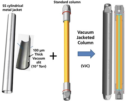
Figure 1: Assembly of the VJC (right image and drawing), which does not require any complex vacuum equipment. A cylindrical metal sleeve (left image) including an open vacuum slit (10-7 Torr, 100-µm thickness) wraps the chromatographic column (middle image) over its entire length. Note that a fraction of the external surface area of two bulky stainless steel endfittings is still in contact with the external environment.
This is confirmed from infrared (IR) thermal images that show the difference in heat leaks between the VJC and the punctured VJC. Overall, for the sake of reproducibility, four different VJC columns (2.1 mm × 100 mm, packed with sub-2-µm particles) were embedded in the large (6 cm i.d.) vacuum chamber, and their efficiency measured at air pressures of 760 Torr (heat can then be exchanged by convection and diffusion modes), 5 Torr (heat can be exchanged by diffusion mode only), and 10-5 Torr (heat can only be exchanged by residual electromagnetic radiation). The efficiencies were also measured when placing the VJC inside the oven of the UHPLC instrument (similar to 5 Torr air pressure in the vacuum chamber, heat can be only exchanged by diffusion). All the efficiency results were measured for six small analytes (uracil, acetophenone, propiophenone, butyrophenone, valerophenone, and n-hexanophenone). On average, the efficiencies of the four VJCs measured at 760 Torr (representing laboratory still-air thermal environment) are equal to 96% (column 1), 96% (column 2), 94% (column 3), and 97% (column 4) of the maximum theoretical efficiency (100% at 10-5 Torr air pressure). These results reveal that the user-friendly VJC operates under quasi-adiabatic conditions; the small relative loss (close to -5%) in column efficiency was a result of residual heat leaks at the hot column outlet endfitting, which is not fully insulated by the thin vacuum slit embedded in the metal jacket (Figure 1).
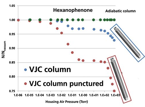
Figure 2: Plot of the experimental column efficiency versus the air pressure imposed in a large 6-cm i.d. vacuum chamber placing the column in fully adiabatic conditions. Benefit of the VJC (filled blue circles) with respect to the same but punctured VJC (the high vacuum in the 100-µm slit is disrupted, filled brown circles). At 1 Torr and 760 Torr, the relative efficiency losses with respect to the fully adiabatic column (filled green circles) are only 3% and 7%, respectively, for the VJC against 15% and 25% for the punctured VJC. Experimental conditions: flow rate 0.7 mL/min, ΔP = 850 bar (frictional heating power 10 Watts/m), isocratic mobile phase: 70:30 acetonitrile-water (v/v), Teluent = laboratory temperature.
Easy Deployment of VJCs to Optical Detectors at High Temperatures Without Oven
As demonstrated in the previous section, the VJC behaves nearly identically to the fully adiabatic column when the eluent temperature is set at room temperature. The heat leaks causing the 5% loss in column efficiency under extreme viscous heating conditions (10 Watts/m) are located at the outlet endfitting. Similar experiments were performed at elevated eluent temperatures (from room temperature to 90 °C imposed by the active eluent preheater of the UHPLC instrument), while the VJC column was placed outside the column oven directly connected the inlet port of the ultraviolet (UV) detection cell (see Figure 3). Because the column is operated under quasi-adiabatic conditions, the use of a temperature oven is no longer required, and VJCs are then easily deployed directly to the inlet port of any detector (UV, refractive index [RI], fluorescence) while reducing post-column dispersion. The comparison between the gradient performances (peak capacity) of the VJC column (2.1 mm × 100 mm, packed with sub 2 µm particles, 0.7 mL/min, 1–99% acetonitrile gradient in 3 min) when it is deployed directly to the UV cell and when it is placed in the UHPLC oven was investigated at different temperatures of the entering mobile phase. Remarkably, despite a reduction in pressure drop and frictional heating, the performance of the deployed VJC is 2–15% lower than that of the same VJC in the instrument oven when increasing the inlet temperature from 25–60 °C. This loss in gradient performance is now caused by the increasing intensity of the heat leaks from both the hot inlet and outlet endfittings of the deployed VJC to the cool laboratory air (the laboratory temperature is set at 25 °C). A practical solution to this loss in gradient performance was proposed as shown in Figure 3: two small heaters were placed on the inlet and outlet end nuts of the column. The temperatures Teluent of the eluent entering the column (set by the active preheater of the UHPLC instrument), Tinletnut of the inlet end nut (set by one small heater), and Toutlet nut of the outlet end nut (set by the second small heater) are controlled independently. For instance, Figure 4 shows the relative change in gradient peak capacity (with respect to that of the VJC placed in the oven, Teluent = Toven = 40 °C, no heaters added) when keeping Teluent at 40 °C, the inlet heater passive ("Ioff"), and stepwise increasing Toutlet nut from the laboratory temperature ("Ooff") to 40, 50, 60, 70, 80, and 90 °C. The experimental results reveal two poor Tinlet/Tinlet nut/Toutlet nut combinations: 40 °C/ off / off or 40 °C. This can be easily explained from a qualitative viewpoint by estimating the intensity of the heat leaks at both column ends. The deployed VJC can be segmented into three zones: the inlet and outlet zones (about 1.5 cm long), where heat leaks occur, and the middle zone (7 cm long for a 10 cm long column), which is well thermally insulated. Accordingly, for the temperature combination 40 °C / off / off or 40 °C, the radial heat flux in both the inlet and outlet zones is oriented in the same direction: from the inlet column center (40 °C + ΔTinlet from frictional heating, yellow color) to the laboratory air (25 °C, white color) and from the outlet column center (40 °C + ΔToutlet > 40 °C + ΔTinlet from heat friction, red color) to the laboratory air (25 °C, white color). As a result, the peak widths are adversely affected at both column ends (relative peak capacity losses of -15% and -9% for Toutlet nut = off and 40 °C, respectively). Note that in the thermally insulated middle zone, heat leaks are always negligible, and they do not contribute much to peak width enlargement besides the usual and expected sample dispersion along packed beds in the absence of radial temperature gradients. In contrast, the temperature combinations 40 °C / off / 60 °C or 70 °C (green color frame) are very close to the optimum combination (40 °C / off / 65 °C) for a relative peak capacity gain of +7%; in this case, the heat flux direction is reversed from the inlet to the outlet zone. It is still from the inlet column center, but it is now from the laboratory air (60–70 °C, white color) to the column center (40 °C + ΔToutlet < 60 °C) at the outlet as a result of the "high enough" temperature applied by the heater to the outlet end nut. The initial peak deformation occurring at the inlet is then partially compensated at the column outlet. However, if Toutlet nut becomes too large (for example, 90 °C), overcompensation occurs and the change in peak capacity returns to negative. This compensation phenomenon is similar to that previously reported in SFC using low-density mobile phases (carbon dioxide above 100 °C, outlet pressure below 100 bar) where the temperature of the inlet eluent was controlled independently from that of the column oven (11).
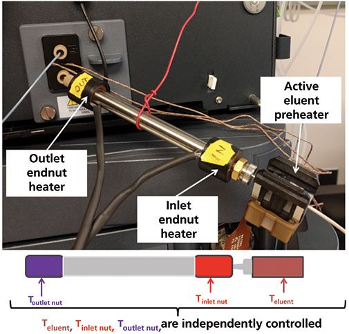
Figure 3: Deployment of the VJC directly at the cell of an optical UV-vis detector. Note that the inlet eluent temperature set by the active eluent preheater (Teluent), the temperature imposed at the surface of the inlet endfitting by the inlet end nut heater (Tinlet nut), and the temperature imposed at the surface of the outlet endfitting by the outlet end nut heater (Toutlet nut) can be controlled independently.
Improved LC–MS Hyphenation with Zero Post-Column Dispersion
Most applications in LC analyses involve MS detection. The column outlet is usually connected to the ionization MS probe of the mass spectrometer. This causes post-column sample dispersion after the sample zone has eluted through long (up to 60–70 cm) and large internal diameter (100–125 µm) connecting tubes. This significantly affects the efficiency and gradient peak capacity of the column. For example, for a 2.1 mm × 100 mm column packed with sub-2-µm particles and a standard LC–MS interface (column → divert/infusion valve → ESI probe), the post-column sample dispersion is as large as 4.3 µL2, while the column dispersion (k = 1 at elution) is only 1.8 µL2. This means that only 30% and 55% of the expected column efficiency and peak capacity, respectively, can be observed after MS detection. A solution to that problem was proposed by coupling the chromatographic column directly to the ESI probe as shown in Figure 5. The conventional ionization probe is extended to a vacuum-jacket assembly, which accommodates the chromatographic column into the cylindrical insulating metal jacket. The assembly is then closed with a cap containing a newly designed eluent preheater. In addition, the MS probe conserves all its functionalities by designing a T-junction between the column outlet, the side tubing (used for MS lock-spray, calibration, direct infusion, make-up flow, and diversion), and the ESI probe tube.
The proof-of-concept of this new research prototype LC–MS interface was tested regarding the separation of small molecules (acetaminophen, propranolol, diltiazem, sulfadimethoxone, verapamil, reserpine, and terfenadine) under challenging (10 Watts/m frictional heating) gradient chromatographic conditions (2.1 mm × 100 mm column, packed with sub 2 µm particles, gradient: 1–99% B in 3 min, A: 0.1% formic acid, B: 0.1% formic acid in acetonitrile, flow rate: 0.7 mL/min, inlet temperature 40 °C, ESI+). The MS chromatograms recorded for the standard LC–MS system (standard column, 60 cm × 100 µm + 75 cm × 125-µm connecting tubes between the column outlet and the ESI probe) and the new VJC-ESI probe interface are shown in Figure 6. The observed relative gain in peak capacity was +110%. This is illustrated in the peak shape of the compound diltiazem in the right insert in Figure 6. This relative gain is explained by i) the nearly complete elimination of the post-column dispersion up to the T-junction and ii) the improved gradient performance of the quasi-adiabatic VJC with respect to the standard column placed in a standard oven.
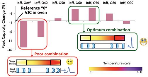
Figure 4: Experimental relative change of the peak capacity of the deployed VJC as a function of the temperature imposed at the outlet endfitting, from Toutlet nut = "off" (not imposed, passive heater), 40, 50, 60, 70, 80, and 90 °C (from left to right). The inlet eluent temperature is set constant at Teluent = 40 °C, and the temperature at the inlet endfitting is not imposed ("off" or passive heater). The reference performance is for the VJC in the Acquity oven at 40 °C. Gradient experimental conditions: column: 2.1 mm × 100 mm, 1.6-µm 90Å Cortecs-C18 (Waters), gradient: 1-99%B in 3 min, A: 0.1% formic acid, B: 0.1% formic acid in acetonitrile, flow rate: 0.7 mL/min. Sample mixture: acetaminophen, propranolol, diltiazem, sulfadimethoxone, verapamil, reserpine, and terfenadine. Note the optimum VJC performance when the direction of the heat flux is reversed from the inlet to the outlet of the column (temperature compensation-peak refocusing effect) for Toutlet nut ~65 °C.
Conclusion
This article has demonstrated that it is possible to design an easy-to-use (regular size) column under a quasi-adiabatic environment without depending on cumbersome vacuum accessories (such as oil pumps, turbomolecular pumps, stainless steel tubes, and rubber O-rings), which make routine LC and SFC analyses impractically long. In order to achieve this, the chromatographic column is simply wrapped in a cylindrical insulating metal sleeve acting as a thermal barrier between its inside and outside faces; this defines the VJC.
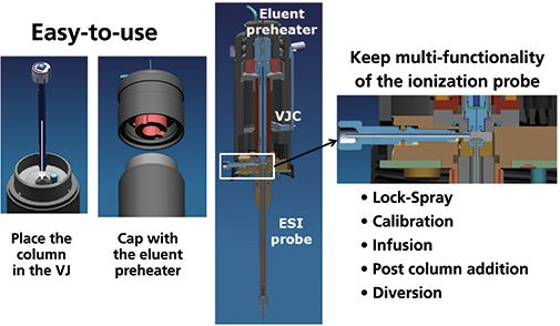
Figure 5: Improved LC-MS coupling (VJC-MS probe) between the eluent preheater, the chromatographic column, and the ESI probe for maximum performance when MS detection is required. The standard LC column is wrapped by a metal insulating sleeve placed in the extension of the ESI probe, which is capped by a small size eluent preheater. Note the presence of the T-junction joining together the column outlet, a divert tube (for various MS functionalities indicated in the legend), and the ESI probe.
Experimental results show that 95% of the maximum expected column efficiency is achieved when operating under intense frictional heating conditions (10 Watts/m) at room temperature. The 5% efficiency loss is caused by the residual heat leaks at both column ends. In addition, the VJC can be easily deployed to any optical detectors without highly dispersive post-column connecting tubes and the constraining presence of the column oven manager when operating the column at elevated temperatures. Performance even superior to that of the same VJC but placed in a conventional oven can be achieved by independently fixing the temperature of the inlet and outlet endfittings to sharpen and minimize the peak width at exactly the detection point.
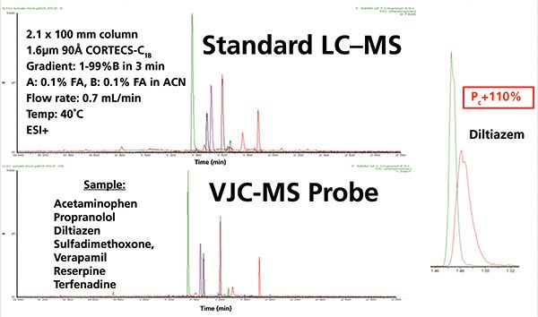
Figure 6: Experimental evidence of the gain (+110%) in peak capacity for the improved LC-MS coupling shown in Figure 6 (VJC-MS probe) with respect to the gradient performance observed with a standard LC (i-class Acquity UPLC) -MS (Xevo TQD MS) coupling. The VJC-ESI probe coupling allows for both increased column performance under severe frictional heating conditions and elimination of post-column sample dispersion. Same gradient experimental conditions as those in Figure 4.
Most importantly and for routine applications involving MS detection, a nearly zero-dispersion VJC-ESI probe interface was designed. The advantages of the VJC-ESI probe interface are twofold: i) maximum column performance of the VJC under extreme viscous heating conditions (as a result of the presence of the insulating metal sleeve) and ii) significant reduction of the post-column sample dispersion of a standard LC–MS system (by getting rid of unnecessarily long and wide internal diameter connecting tubes). Overall, the peak capacity of narrow-bore columns (2.1 mm × 100 mm long) packed with sub-2-µm particles is more than doubled with respect to the classical LC–MS configuration.
Acknowledgments
The author would like to thank Mike Fogwill, Martin Gilar, Jason Hill, Joseph A. Jarrell, Wade Leveille, and Joseph Michienzi (Waters Corporation, Milford, Massachusetts, USA) for their constant technical contributions, fruitful discussions, and suggestions for this research project.
References
(1) F. Gritti, LCGC North America 36(s6), 18–23 (2018).
(2) F. Gritti, M. Gilar, and J. Jarrell, J. Chromatogr. A 1456, 226–234 (2016).
(3) H.-J. Lin and Sc. Horvath, Chem. Eng. Sci. 36, 47–55 (1981).
(4) F. Gritti and G. Guiochon, Anal. Chem. 80, 5009–5020 (2008).
(5) F. Gritti and G. Guiochon, Anal. Chem. 80, 6488–6499 (2008).
(6) J. Kostka, F. Gritti, G. Guiochon, and K. Kaczmarski, J. Chromatogr. A 1217, 4704–4712 (2010).
(7) K. Kaczmarski, F. Gritti, J. Kostka, and G. Guiochon, J. Chromatogr. A 1216, 6575–6586 (2009).
(8) D. Poe and J. Schroden, J. Chromatogr. A 1216, 7915–7926 (2009).
(9) F. Gritti, M. Gilar, and J. Jarrell, J. Chromatogr. A 1444, 86–98 (2016).
(10) F. Gritti, M. Fogwill, M. Gilar, and J. Jarrell, J. Chromatogr. A 1468, 217–227 (2016).
(11) F. Gritti, M. Fogwill, M. Gilar, and J. Jarrell, J. Chromatogr. A 1472, 107–116 (2016).
(12) T.L. Bergman, A.S. Lavine, F.P. Incropera, and D. Dewitt, Fundamentals of Heat and Mass Transfer, (John Wiley and Sons, Hoboken, New Jersey, USA, 7th ed., 2011).
(13) G.D. Raithby and K.G.T. Hollands, in Advances in Heat Transfer (Academic Press, New York, New York, USA, vol. 11, 1975), pp. 265–315.
Fabrice Gritti is a Principal Consulting Scientist at Waters Corporation, in Milford, Massachusetts. Direct correspondence to: Fabrice_Gritti@waters.com

Extracting Estrogenic Hormones Using Rotating Disk and Modified Clays
April 14th 2025University of Caldas and University of Chile researchers extracted estrogenic hormones from wastewater samples using rotating disk sorption extraction. After extraction, the concentrated analytes were measured using liquid chromatography coupled with photodiode array detection (HPLC-PDA).
Polysorbate Quantification and Degradation Analysis via LC and Charged Aerosol Detection
April 9th 2025Scientists from ThermoFisher Scientific published a review article in the Journal of Chromatography A that provided an overview of HPLC analysis using charged aerosol detection can help with polysorbate quantification.
Removing Double-Stranded RNA Impurities Using Chromatography
April 8th 2025Researchers from Agency for Science, Technology and Research in Singapore recently published a review article exploring how chromatography can be used to remove double-stranded RNA impurities during mRNA therapeutics production.


