Troubleshooting Basics, Part IV: Peak Shape Problems
LCGC North America
In a well-behaved method, changes in peak shape should occur gradually over hundreds or thousands of samples. Tailing of one or a few peaks usually points to a problem.
What do you do when the peak shape changes?
A change in peak shape is one of the most common observations of problems with a liquid chromatography (LC) method. Because of this, most system suitability tests include a measure of peak shape, so a quantitative value of peak shape can be tracked over time. Poor peak shape can compromise the results of an analysis by degrading resolution between closely eluted peaks and reducing precision and accuracy of measuring peak area, especially for small peaks. A change in peak shape is one of the first signs that the column is failing, but there are other causes of peak tailing, as well. This month we look at several aspects of peak tailing as we continue our "Troubleshooting Basics" series of column installments (1–3).
Measuring Peak Tailing
The ideal chromatographic peak will have a Gaussian shape, but it is rare that a perfectly symmetric peak is observed in real chromatograms. Most peaks tail slightly, and as the column ages, tailing typically increases. However, there are several other potential causes of peak tailing (or fronting) as well, so it is a good idea to track the peak shape over time to anticipate when practical problems will occur. As a result, nearly all system suitability tests include a measurement of peak shape.

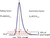
Figure 1: Measurement of tailing factor and asymmetry factor.
The two most popular methods of measuring peak shape are illustrated in Figure 1. Other methods to measure peak shape are used much less often. The pharmaceutical industry uses the tailing factor, TF, which is determined by measuring the entire peak width at 5% of the height and dividing it by twice the front half-width. Nonpharmaceutical laboratories often use the asymmetry factor, As, which is calculated by measuring the back half-width of the peak at 10% of the peak height and dividing it by the front half-width. You can see that if the peak is perfectly symmetric, the front and back half-widths will be the same, no matter where they are measured relative to the peak height, so for such peaks, TF ≡ As. As tailing increases, however, the two numbers diverge, with As growing faster than TF, but for peaks with a value less than 2 there is not a very noticeable difference. There is no inherent value in using one technique versus the other for measuring peak shape; rather, it is important to choose one technique and use it to look for changes in peak shape over time.

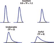
Figure 2: Examples of tailing peaks.
Most LC peaks tail or front a bit, so column manufacturers typically set their column-release specifications at 0.9 < TF < 1.2 as normal performance. As can be seen in Figure 2, when tailing increases, several practical problems can arise. The peaks are harder to integrate because the transition from the baseline to the peak or peak to baseline is much more gradual, and on noisy or sloping baselines the peak limits are difficult to determine. Generally, the peak area stays constant, so increased peak tailing translates into shorter peaks, and peak height is the limiting factor in determining detection limits, so method limits can suffer with tailing peaks. Tailing peaks also take a larger time window to be eluted, so to achieve baseline resolution between peaks, the run time must be longer. And tailing peaks are aesthetically less pleasing. You can see that all these factors favor symmetric peaks. From a practical standpoint, peak tailing is difficult to eliminate, however, for many applications peaks with TF ≤ 1.5 are acceptable. When TF ≥ 2, usually corrective action should be taken to identify and eliminate the source of tailing.
When peak tailing occurs, it usually shows up for one or just a few peaks in the chromatogram, but sometimes all the peaks in the run tail. The appearance of peak fronting is much less common. Most often, these three behaviors are caused by three different sources. We will look at each of the three problems next.
Tailing of One or a Few Peaks
Usually, one or a few peaks in the chromatogram tail and the cause is most often chemical in nature. The problem may appear during method development, in which case you probably do not know if the peak shape ever was good. Or more often with an existing method, a peak that had acceptable shape in the past begins to tail, and tailing increases over time. If the onset of the tailing was sudden, as when a new batch of samples was run, look for some other change that coincided with the observation, such as preparation of a new batch of mobile phase or replacement of the column or guard column.
Mobile-phase changes are the easiest to check. For example, the pH of the mobile phase can have a strong influence on the peak shape, so if an error was made in pH adjustment, this could be the problem source. Mobile-phase problems will also usually cause changes in retention time. If such correlated changes are observed, carefully prepare another batch of mobile phase (or repeat some other change that was made) and see if that corrects the problem. Sometimes a method will be developed that is not very robust. In such cases, even small changes in temperature or other variables can cause a change in the retention or peak shape. Another mobile-phase problem that occurs occasionally is insufficient buffer concentration. Although reversed-phase separations are not strongly affected by buffer concentration, hydrophilic interaction chromatography (HILIC) and ion-exchange are much more sensitive to buffer effects. A buffer concentration of 5–10 mM usually is adequate to buffer the mobile phase, column, and injection solvent in reversed-phase separations. If buffer concentration problems are suspected, double the concentration and see if this fixes the peak shape.
After the mobile phase is eliminated as the problem source, look to the column. If a guard column is in use, remove it and make an injection. If the peak is OK after that is done, the guard column has failed. If the problem persists without a guard column, substituting a new column for the old one is the simplest way to check for other column problems. Column problems are more likely after ≈500 or more samples have been run, but in some cases column problems can occur much earlier. Dirty samples and mobile phases outside the 2 < pH < 8 range are two common sources of rapid column deterioration. If replacing the column corrects the problem, consider improving the sample cleanup, changing the mobile-phase pH, or using a guard column to help delay the problem of column deterioration.

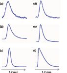
Figure 3: Peak tailing for (aâc) mefanamic acid and (dâf) amitriptyline at pH 2.8. Injection mass on column: (a,d) 3 ng; (b,e) 500 ng; and (c,f) 15 µg.
The source of peak tailing is not a simple process. In Figures 3a–3c, you can see the influence on peak shape of increasing amounts of mefanamic acid. Under these conditions (pH 2.8), the mefanamic acid is well below its pKa, so it is not ionized. At low loading (Figure 3a), the tailing is dramatic. Peaks with exponentially shaped tailing are likely a result of two different retention processes going on simultaneously; for example, some molecules might be interacting with column sites that equilibrate slowly (those on the tail) and some with sites that equilibrate quickly (those on the main peak). As the mass on column increases (Figures 3b and 3c), the majority of the sample molecules are retained by a single mechanism (fast equilibration), and the peak shape improves. The slow equilibration process doesn't disappear, but it is a smaller portion of the total, so tailing is reduced. On the other hand, amitriptyline, an ionized base at pH 2.8, looks better than mefanamic acid at low concentrations (compare Figures 3a and 3d). As the injected mass of amitriptyline increases (Figures 3e and 3f), two things are observed. First, the peak tail begins to change shape until it takes on a right-triangle appearance (Figure 3f). Second, the retention time gradually gets smaller. These are two classic symptoms of column overload. To verify this problem source, reduce the sample mass on column and see if retention increases and tailing improves. The cause of tailing in this case is likely because of ion exclusion. As the amount of amitriptyline adsorbed inside the pores in the column increases, the pore takes on a net positive charge (amitriptyline carries a positive charge at pH 2.8). At some point, the positive charge inside the pore is sufficient to repel another positively charged molecule, so it must travel further down the column before it finds a compatible site on the surface. The interesting thing about these two examples is that at the same pH, one analyte (mefanamic acid) gives less tailing as the sample load increases, whereas the other (amitriptyline) gets worse. It is hard to generalize about the source of peak tailing.
Peak Fronting
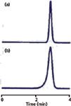
Peak tailing was attributed to problems related to chemical interactions on the column. One way of thinking about peak tailing is that the active sites — the places on the column where interactions between the analyte molecules and the chemical surface of the column occur — become saturated. It is possible to conceive of a similar case in which the mobile phase becomes saturated or overloaded, and in such cases, peak fronting would occur. This indeed happens, but with reasonable buffer concentrations (for example, ≥5 mM), such overload is rare in reversed-phase LC. A more common source of peak fronting is illustrated in Figure 4, where peaks from two consecutive injections are shown. The peak changes from a normal appearance in injection number 527 (Figure 4a) to badly fronting in injection 528 (Figure 4b). The most common cause of such changes is a sudden physical change in the column, usually referred to as column collapse. In the present case, the column was operated at pH 9.6 at 70 °C, but the column was designed to be used at pH ≤ 7 and ≤ 40 °C. The aggressive mobile phase conditions gradually dissolved the silica particles inside the column until they became so fragile that the minor shock of the injection valve rotating caused the internal column structure to collapse. The proper fix for such a problem would be to modify the method so that it operated with the recommended limits of the column or replace the column with a more robust one. That is, if all else fails . . . read the directions! However, for the present example, it made more sense economically to replace the column every 500 injections rather than redevelop and revalidate the method.

Figure 4: Peak fronting for two consecutive injections: (a) 527 and (b) 528.
If All Peaks Tail
When all peaks in the chromatogram tail or are split or doubled, as in Figure 5, this is a symptom of a problem that happens at the inlet of the column before any separation takes place. The most common cause of such problems is a partially blocked inlet frit on the column. Debris from the sample, the mobile phase, or a failed pump seal or injector rotor can collect on the inlet frit. As the frit becomes partially blocked, the sample stream arriving at the column inlet is distorted, resulting in peak distortion. Because this problem happens before any sample molecules are separated, it affects all peaks in the chromatogram in the same manner. You can fix the problem about a third of the time by reversing the column and backflushing it to waste for a few minutes. Most columns can be reversed for such flushing, but it is best to check the column care-and-use instructions to make sure it is allowed for your column. If reverse-flushing corrects the problem, you can proceed as normal. If it doesn't, replace the column. In either case, it is wise to eliminate or reduce the source of particles arriving at the top of the column. Improve the sample pretreatment by adding a centrifugation or filtration step. Replace worn pump or autosampler parts. Filter the mobile phase to remove particles. And a good safety measure is to place an in-line filter between the autosampler and the column. If you use a guard column, it acts as a filter to protect the column, but the in-line filter is less expensive than the guard column and easier to service, so I recommend using one in every system, even if you are using a guard column.

Figure 5: Peak distortion for all peaks in the chromatogram.
Conclusions
Changes in peak shape over time are common in the use of LC methods, but in a well-behaved method, such changes should occur gradually over hundreds or thousands of samples. Tailing of one or several peaks usually points to a problem with some chemical aspect of the system, so check the mobile phase and column for problems. When all the peaks tail or are similarly distorted, it is a sign that particulate matter is collecting at the top of the column. Better sample preparation and protection of the column will help to avoid this mode of failure. Peak fronting can result from chemical problems in the system, but is more commonly attributed to catastrophic column failure, usually resulting from using the column outside the recommended operating limits. Check the column instructions for the column limits, change to a more robust column, or expect to replace the column more often.
Although peak shape changes are a sign of problems and are difficult to avoid, if a method is developed and tested for robustness, such problems should not be a major concern for the method. A good system suitability test coupled with tracking peak shape over time should allow you to anticipate when peak shape changes will compromise the quality of the data. Take the appropriate corrective action before data are compromised, and your method should be satisfactory.
John W. Dolan "LC Troubleshooting" Editor John Dolan has been writing "LC Troubleshooting" for LCGC for more than 25 years. One of the industry's most respected professionals, John is currently the Vice President of and a principal instructor for LC Resources, Walnut Creek, California. He is also a member of LCGC's editorial advisory board. Direct correspondence about this column via e-mail to John.Dolan@LCResources.com.

John W. Dolan
References
(1) J.W. Dolan, LCGC 29(7), 570–574 (2011).
(2) J.W. Dolan, LCGC 29(9), 818–824 (2011).
(30) J.W. Dolan, LCGC 29(12), 1046–1050 (2011).
Erratum
A calculation on page 394 of the May installment of "LC Troubleshooting" (LCGC North America 30[5], 392–400 [2012]) was incorrect. The calculation showed that 0.1% × 0.1% = 0.01%, when in fact it should have been 0.1% × 0.1% = 0.0001%.

Accelerating Monoclonal Antibody Quality Control: The Role of LC–MS in Upstream Bioprocessing
This study highlights the promising potential of LC–MS as a powerful tool for mAb quality control within the context of upstream processing.
Using GC-MS to Measure Improvement Efforts to TNT-Contaminated Soil
April 29th 2025Researchers developing a plant microbial consortium that can repair in-situ high concentration TNT (1434 mg/kg) contaminated soil, as well as overcome the limitations of previous studies that only focused on simulated pollution, used untargeted metabolone gas chromatography-mass spectrometry (GC-MS) to measure their success.
Prioritizing Non-Target Screening in LC–HRMS Environmental Sample Analysis
April 28th 2025When analyzing samples using liquid chromatography–high-resolution mass spectrometry, there are various ways the processes can be improved. Researchers created new methods for prioritizing these strategies.
Potential Obstacles in Chromatographic Analyses Distinguishing Marijuana from Hemp
April 28th 2025LCGC International's April series for National Cannabis Awareness Month concludes with a discussion with Walter B. Wilson from the National Institute of Standard and Technology’s (NIST’s) Chemical Sciences Division regarding recent research his team conducted investigating chromatographic interferences that can potentially inflate the levels of Δ9-THC in Cannabis sativa plant samples, and possible solutions to avoid this problem.

.png&w=3840&q=75)

.png&w=3840&q=75)


.png&w=3840&q=75)


.png&w=3840&q=75)


