Thermal Desorption Sampling
LCGC North America
Thermal desorption sampling often provides a means for bringing otherwise intractable samples to a gas chromatography (GC) column for separation and detection. In this installment, John Hinshaw describes the principles of thermal desorption sampling in relationship to other analysis techniques for volatile solutes.
Thermal desorption sampling often provides a means for bringing otherwise intractable samples to a gas chromatography (GC) column for separation and detection. In this installment, John Hinshaw describes the principles of thermal desorption sampling in relationship to other analysis techniques for volatile solutes.
When asked about common sampling techniques, gas chromatographers first envision a liquid inlet system such as what is found on most gas chromatography (GC) systems. Injection of a relatively clean liquid sample into a vaporizing inlet system often suffices to transfer analyte components from their physical state outside the GC column into a state suitable for GC analysis. A vaporizing inlet system heats the sample to vaporize the components of interest, mixes the sample vapor with carrier gas, and then transfers the sample into the GC column. Such injection techniques include direct, split, splitless, on-column, and programmed-temperature methods.
Many other samples present a different problem: They contain nonvolatile materials that can impair a vaporizing inlet’s function when significant quantities of residue are deposited in the inlet or in the beginning of the column. The built-up residue interferes with subsequent analyte transport through the inlet system by causing peak-shape distortion, irreversible adsorption, and thermolytic decomposition. Other samples such as resins, powders, fibers, plastics, and biological fluids present a matrix that is simply incompatible with direct injection techniques.
Thermal Desorption
In such cases, gas chromatographers can call upon a number of related techniques that extract relatively volatile analytes from a less volatile sample matrix. Analyte concentration and focusing steps before transfer onto the GC column often accompany such procedures. Purge-and-trap, headspace, and thermal desorption sampling, plus solid-phase microextraction (SPME) add a number of sampling-stage steps that make them suitable for solid and liquid samples in difficult matrices.
Thermal desorption sampling refers to a number of related techniques that include one or more steps in which sample heating releases volatile analytes into the carrier-gas stream from an adsorbent or other involatile material. One or more adsorption–desorption steps serve to concentrate analytes as well as reduce their bandwidths to meet column injection requirements. Volatiles enter the desorption tube from a variety of sources, including directly from the atmosphere, from the headspace over a solid or liquid sample, by sparging a liquid sample with inert gas, or as the effluent from a chemical process or engine exhaust. A related technique, thermal extraction, heats a solid or semisolid sample directly in the carrier-gas stream using essentially the same equipment as thermal desorption. To distinguish it from pyrolysis injectors, thermal desorption operates at lower temperatures and does not intentionally cause sample thermolysis. For example, chromatographers can use thermal extraction to sample polymers, waxes, powders, pharmaceutical formulations, solid foods, and cosmetics for their volatile constituents.
The bandwidth or volume that analytes occupy as they approach an open-tubular column is often large enough to prevent the column from delivering all of its peak-resolving potential, especially for early-eluted peaks. Ancillary cold trapping or secondary focusing techniques help reduce analyte bandwidths appropriately. Other problems found in conventional liquid inlet systems from excessive amounts of solvent or nonvolatile residue deposition in the inlet are absent in volatiles extraction techniques such as thermal desorption. Water vapor from atmospheric or aqueous samples, however, may interfere in some cases, and may require additional sample management steps to prevent water-induced side effects.
Thermal Desorption Techniques
In its simplest form, thermal desorption involves heating a sample tube with carrier gas flowing through it. The emerging gas is conducted directly to the GC column. Figure 1 illustrates a simple thermal desorption setup. A tube containing an adsorbent or sample material (or both) is positioned in the carrier gas stream before the column inlet. After a short delay to flush out residual air, the tube is heated and analytes are desorbed or thermally extracted directly from the sample. Carrier flow conducts the released volatile compounds into the column. In practice, an existing inlet can provide a convenient base for a top-mounted desorption system, or it can act as the terminus of a heated transfer line for benchtop systems. After desorption has finished, the tube cools down and normal carrier-gas flow is restored.
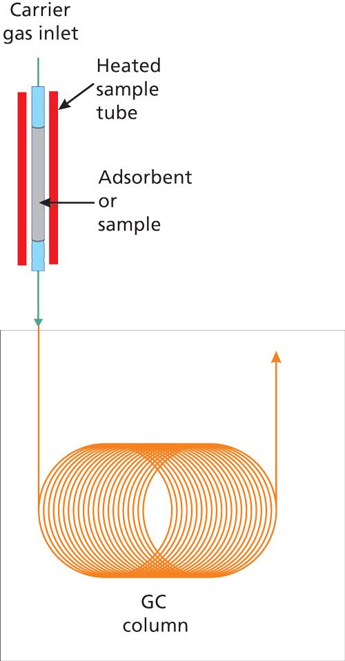
Figure 1: Direct thermal desorption.
This simple scheme suffers from a number of potential difficulties and generally is not used in practice without enhancements. Researchers have developed a variety of solutions, some of which are generally applicable to thermal desorption, while others are more useful for specific sample types. Thermal desorption problem areas include controlling the amount of sample amount entering the column, flow rates through the column and the sample tube, solute breakthrough volumes, and peak bandwidths. These areas are discussed in more detail below.
Sample Amount Entering the Column
Capillary GC columns tolerate a limited analyte mass beyond which column overloading occurs, characterized by peak distortion and broadening plus retention time shifts. Column sample capacity ranges from about 100 ng on a 0.25-mm i.d., 0.25-µm film column up to about 5 µg on a 0.53-mm i.d. column with a 5-µm stationary phase film. Analyte amounts released from thermal desorption or thermal extraction often exceed these levels, and serious performance losses could occur if all the analyte mass contained in a sample tube were permitted to enter the column.
Thermal desorption systems can use in-line sample splitting to control the analyte amounts that traverse the sampling system. A modified capillary column inlet splitter works well for top-mounted samplers, while benchtop systems often use self-contained splitters. Figure 2a shows an outlet splitter inserted after the sample desorption tube. A needle valve or electronic device (not shown) controls the outlet split flow and thus the split ratio from the desorption tube to the column. Split control with electronic pneumatics is possible when the in-line capillary GC inlet system supports it. For trace-level samples, direct transfer conducts all of the material onto the column. Sample splitting also helps to balance flow rates and reduce peak bandwidths by permitting faster tube flow rates and concomitantly faster desorption times.
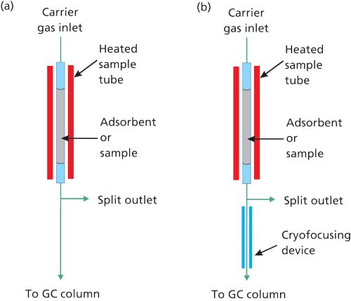
Figure 2: Thermal desorption with (a) stream splitting and with (b) stream splitting followed by a cryofocusing trap.
Flow Rates
Thermal desorption tubes generally have inner diameters of 3–4 mm. With lengths of about 100 mm, tube internal volumes range from 2.8–5.0 cm3. With a typical packing factor of about 0.4, tube void volumes are 1.1–2.0 cm3. Desorption tubes are not packed tightly with adsorbent from end to end, however, to allow space for glass wool or other materials that restrain the packing inside the tube within the heated zone. For this reason, typical void volumes are on the high side of this range. During desorption, when the tube is heated and analytes are no longer retained on the tube packing, a gas volume of at least 4–8 times the void volume should pass through the tube to transfer analytes to the column quantitatively. A desorption tube with the above dimensions needs at least 30 s to heat its contents to the desorption temperature. With these assumptions, a desorption volume of at least 10 cm3 at flow rates of 20 cm3/min or greater is suitable in most cases. If the tube packing slightly retains high-boiling analytes at elevated desorption temperatures, however, the gas volume and the time required for complete desorption increases significantly. In practice, longer desorption times help ensure quantitative transfer from the desorption tube.
For packed columns, desorption flow matches column flow well. However, a disparity exists between the desired desorption flow rate and optimum capillary column flows. At an average helium carrier-gas linear velocity of 40 cm/s and a temperature of 50 °C, the corrected outlet flow rate of a 25-m long, 0.25-mm i.d. capillary column is 1.75 cm3/min, about five times less than the desired desorption flow. For a 25-m long, 0.53-mm i.d. column, the corresponding corrected outlet flow rate is 5.4 cm3/min. This value is closer to the desorption tube flow rate, but still lower by a factor of 2. Without modification, direct connection to a capillary column would require excessively long desorption times to pass even a minimum amount of carrier gas through the tube: about 2–4 min for a wide-bore column and 6–12 min for a narrow-bore column.
A simple solution to this problem is to increase the column flow rate during desorption. This remedy is feasible for wide-bore columns, where the increase is limited to two or three times the optimum flow, and in many cases a wide-bore column can deliver good results with direct sample transfer. For narrow-bore columns, however, the needed increase in flow rate of greater than six times will affect analyte trapping efficiency and focusing at the head of the column, and may require more column inlet pressure than is available.
In-line stream splitting as shown in Figure 2a provides a better solution for nontrace samples with capillary columns. Flow from the desorption tube splits between the capillary column and the vent. Minimum desorption times remain in the 30-s range, and optimum flow persists in the capillary column. However, stream splitting alone may not suffice with trace-level samples for which a high split ratio would reduce analyte amounts below a minimum quantifiable limit. Alternative approaches such as secondary adsorbent trapping can be advantageous, as discussed below.
Peak Bandwidth
For peaks that are significantly retained at the initial column temperature, the time it takes for them to be desorbed from a sample tube and pass onto the column is not of too much concern. Such peaks will be focused at the head of the column by trapping in the stationary phase if their retention factors (k) are greater than about 10 at the initial temperature. Analytes that the column does not retain significantly at the initial temperature, however, hit the column and keep going. The column will not deliver the highest resolution possible for these peaks. Since the minimum desorption time is on the order of 30 s, thermal desorption sampling almost always requires some form of band focusing. Several solutions can help establish narrower initial peak widths for these early eluted analytes.
A cryogenic cooling device at the beginning of the column can effectively trap the more volatile analytes in a sample, along with those less volatile ones that would be trapped anyway, without such a device. Figure 2b shows a cryofocusing trap in a thermal desorption system, positioned just inside the column oven, after a stream splitter. Liquid nitrogen or carbon dioxide cools the cryofocusing zone to below 0 °C during sample tube desorption, and analytes from the sample tube, including the more volatile ones, are trapped there. After desorption is completed, cryogenic cooling is turned off and the cooled area is heated quickly to release the analytes trapped there.
A potential drawback of on-column cryofocusing is the accumulation of water at the head of the GC column when moist materials-for example, foodstuffs-are sampled by thermal extraction. Ice crystals can block the column, and ice on the column surface can affect trapping efficiency. Large amounts of water that are eluted from the column can cause detector problems, too.
Breakthrough Volume
An important characteristic of thermal desorption sampling is the GC column-like behavior of sample tubes packed with active adsorbents. As sample gas bearing analytes passes through an adsorbent bed, the analytes migrate along the length of the tube, just as they would in a GC column, and it is possible for them to traverse the length of the tube and emerge from its exit. The gas volume required for an analyte to do so is termed the breakthrough volume. It is expressed in units of gas volume per gram of adsorbent at a specific temperature, and is equivalent to the specific retention volume, Vgθ, on a packed column if the analyte were to be injected onto the adsorbent trap in a narrow plug. Breakthrough volumes help characterize adsorbents by determining not only the maximum gas volume when accumulating a sample, but also by indicating appropriate desorption temperatures.
If the breakthrough volume is too low at the sampling temperature, which is usually ambient temperature, then the trap will not adsorb the analyte quantitatively from a large sample gas volume. For a safety margin, the gas sample amount should not exceed half the breakthrough volume. If sample splitting is used, then the minimum quantifiable concentration increases accordingly.
After the sample compounds are adsorbed onto a sample tube, all of them must desorb at temperatures less than the maximum limit for the adsorbent. When an analyst is selecting a desorption temperature under the maximum, the highest-boiling or most strongly adsorbed compound determines the desired desorption temperature. The breakthrough volume decreases logarithmically with increasing temperature.
It is imperative to consider all the compounds of interest in a sample in terms of their breakthrough volumes. If lighter, less strongly adsorbed materials are present, and sample collection cannot occur at subambient temperatures, then a second, stronger adsorbent material can augment the sample trapping scheme and extend the overall volatility range of thermal desorption sampling. Figure 3 illustrates a dual-adsorbent sampling tube. Sample gas passes through the weaker adsorbent first, and the higher-boiling, more strongly adsorbed components are trapped there. The lower-boiling, weakly adsorbed components break through the weak adsorbent into the stronger adsorbent where they are trapped. Care must be taken not to allow the higher-boiling components to break through the weak adsorbent; they will be permanently trapped on the strong adsorbent.
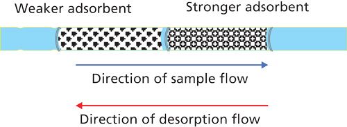
Figure 3: Dual-adsorbent sample tube.
During thermal desorption the flow through a two-adsorbent trap must reverse and backflush the trap. If thermal desorption were to take place in the forward flow direction, then high-boiling materials from the weaker adsorbent would irreversibly encounter the strong adsorbent, just as if they had broken through to it during sampling. During backflush desorption, material from the strong adsorbent passes through the weak adsorbent without effect on its way out of the sample tube.
Multiple adsorbents extend the range of thermal desorption sampling to include compounds that quantitatively adsorb and desorb from either of two adsorbents in the same sample tube. The two adsorbents should be complementary in the range of suitable compounds. The maximum desorption temperature for a multiple-adsorbent sample tube is the lowest of the maximum temperatures for all included adsorbents. Good sources of information about adsorbents and trapping of specific compounds are available from the manufacturers of thermal desorption hardware and adsorbent tubes.
Secondary Trapping
With single or multiple adsorbents, forward- or back-flushed, the desorption time, volume, and flow rate from a conventional sample tube are not well matched to capillary column requirements. If the sample tube were much smaller, its desorption and flow characteristics would be a better match because it could be heated more rapidly, but its breakthrough volumes and sampling characteristics would not be suitable for collection of larger sample volumes. Nor would such a tube be well suited to direct thermal extraction. However, a small additional adsorbent trap positioned in-line between the sample tube and the column can serve both as a focusing device for desorbed analytes as well as a means to better balance the flow rates of the column and the sample tube. Figure 4 shows a small secondary adsorbent trap positioned between the sample tube and the column. Additional valving (not shown) creates the flow paths shown in Figures 4a and 4b. In Figure 4a, carrier gas flows directly into the column and isolates the two traps from the column. During sample desorption or thermal extraction, the sample tube heats up and desorption gas flow conducts released analytes past the first split point into the secondary adsorption trap, which is cooled to ambient temperature or below.
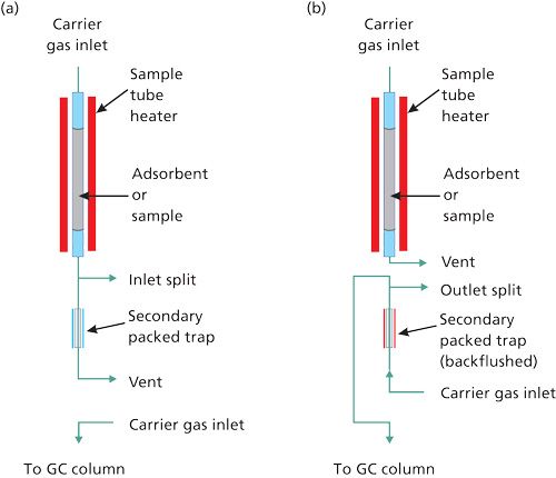
Figure 4: Thermal desorption with secondary trap: Desorption of (a) the primary sample tube and (b) the secondary trap.
After desorption is completed, flow switches to the arrangement shown in Figure 4b. At that point, desorption flow continues to purge the sample tube, while carrier gas flows through the secondary trap in the backflushed direction. The secondary trap is heated rapidly to desorb the analytes quickly. They pass through an optional second split point and then into the column.
The secondary trap contains only a small amount of an adsorbent, 10–20 mg, which can be the same single or multiple adsorbent material as used in the main sample tube. Adsorption breakthrough volumes on the secondary trap are concomitantly lower, but they are greater than the desorption volumes from the primary sample tube. Operation of the secondary trap at subambient temperatures also helps to increase the breakthrough volumes there.
The smaller inner diameter and shorter length of the secondary trap bring its desorption time, flow, and volume down to capillary column levels. A typical heating rate for the packing inside the secondary trap is 40 °C/s, so that it can reach a 200 °C desorption temperature in around 5 s. At elevated temperatures, the minimum desorption volume in such a trap is 1–2 mL, which is about 10 times less than for a primary sample tube. This lower volume opens the possibility for splitless transfer into a capillary column with trace-level samples, although some form of on-column focusing is still required at narrow-bore capillary column flow rates.
A secondary trap also helps with direct thermal extraction. With suitable hydrophobic adsorbents and trap temperatures, water from moist samples will not be adsorbed on the secondary trap, but will pass through the trap to vent. Water that does condense or freeze in the secondary trap is better tolerated there than at the head of the GC column; ice crystals or water droplets will not block gas flow. Subsequent stream splitting during secondary trap desorption reduces the amount of water actually entering the column.
The secondary trapping scheme is not without its drawbacks. It is considerably more complex than other systems and requires a more in-depth knowledge of thermal desorption principles for effective use. The mechanical implementation includes extra valves and tubing, all of which must be inert toward the sample materials and free of cold spots. But the additional complexity may be justified by the ability to handle difficult samples and the flexibility that comes along with secondary adsorbent trapping.
Conclusion
GC sampling techniques for volatiles are highly developed. Analysts can call upon a wide variety of methods for sampling volatiles from difficult matrices, including headspace, thermal desorption, solid-phase microextraction, and purge-and-trap sampling. Thermal desorption techniques present good methods for the concentration of gaseous samples from a variety of sources, including the headspace over solids and liquids, atmospheric samples, and process effluents. Direct thermal extraction of otherwise intractable samples is also possible with thermal desorption equipment.
Researchers have developed a variety of thermal desorption techniques. The need to accommodate capillary columns for large gas samples that span a wide volatility range has spurred development of ancillary methods for thermal desorption samplers, including on-column cryotrapping, sample stream splitting, multiple-adsorbent sample tubes, and secondary adsorbent traps. To be successful with thermal desorption sampling, chromatographers must pay careful attention to the relationships between the adsorption–desorption characteristics of trapping materials, the range of sample components and sample matrices to be analyzed, and the kind of equipment that will perform the sampling and analysis.

John V. Hinshaw
“GC Connections” editor John V. Hinshaw is a Senior Scientist at Serveron Corporation in Beaverton, Oregon, and a member of LCGC’s editorial advisory board. Direct correspondence about this column to the author via e-mail: lcgcedit@lcgcmag.com

New Study Reviews Chromatography Methods for Flavonoid Analysis
April 21st 2025Flavonoids are widely used metabolites that carry out various functions in different industries, such as food and cosmetics. Detecting, separating, and quantifying them in fruit species can be a complicated process.
University of Rouen-Normandy Scientists Explore Eco-Friendly Sampling Approach for GC-HRMS
April 17th 2025Root exudates—substances secreted by living plant roots—are challenging to sample, as they are typically extracted using artificial devices and can vary widely in both quantity and composition across plant species.
Sorbonne Researchers Develop Miniaturized GC Detector for VOC Analysis
April 16th 2025A team of scientists from the Paris university developed and optimized MAVERIC, a miniaturized and autonomous gas chromatography (GC) system coupled to a nano-gravimetric detector (NGD) based on a NEMS (nano-electromechanical-system) resonator.
Miniaturized GC–MS Method for BVOC Analysis of Spanish Trees
April 16th 2025University of Valladolid scientists used a miniaturized method for analyzing biogenic volatile organic compounds (BVOCs) emitted by tree species, using headspace solid-phase microextraction coupled with gas chromatography and quadrupole time-of-flight mass spectrometry (HS-SPME-GC–QTOF-MS) has been developed.

.png&w=3840&q=75)

.png&w=3840&q=75)


.png&w=3840&q=75)


.png&w=3840&q=75)


