The Reality Behind Column Insertion Distance
Column insertion distance is critical to good chromatography. What happens if the column is installed is too low in the injection port? Is insertion distance more important when performing split injection, or splitless injection? Does the position of the column in the injection port impact reproducibility?
In our last article, we evaluated wool in different positions in the liner which included wool at the top, wool at the bottom, wool at the center, and no wool. Not surprisingly, wool at the center for split injections provided the best vaporization of the sample and thus low relative standard deviations and high recoveries for a broad range of compounds (1). This is because the heat sensor and heating element are located at the center of the injection port which means a set point of 250 °C represents the temperature in the middle of the injection port where the top and bottom can be 100 °C cooler (2). In splitless mode, position of the wool was less critical since the sample is trapped during the hold time in the injection port allowing more time for complete vaporization.
Building on this work if we use optimized conditions and wool in the correct position what are the effects to the system when the column is installed too high or too low in the injection port? An article on gas chromatography (GC) troubleshooting referred to column installation this way: “column installation is critical, and poor installation can lead to reduced efficiency (broad peaks), peak shouldering or splitting and poor quantitative reproducibility (3).”
In this work, split and splitless conditions will be used to evaluate different column insertion distances starting from 0.5 mm to 20 mm. In addition, several other factors will be explored to better understand low response from high molecular weight compounds during a splitless injection.
Experimental Design
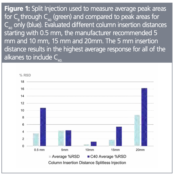
The column used for this work was a 5% diphenyl 95% polydimethylsiloxane, “5-type phase,” (Restek) 30 meters, 0.25 mm internal diameter with a 0.25 µm film thickness installed into a flame ionization detector (FID) with a flow of 1 mL/min. GC oven program of 45 °C (hold 2 min) 20 °C/min to 350° (hold 5 min) was used for both split and splitless injections. The split conditions of 10:1 were used with a precision-style liner where the wool is held in position by baffles. The splitless hold time was set for 1.5 min using a precision-style liner. Compounds chosen were even numbered alkanes ranging from C8 (n-octane) to C40 (n-tetracontane) in hexane. Concentrations were adjusted to maintain 50 ng on column for both split and splitless. Split and splitless conditions were tested with using an Agilent 7890 gas chromatograph with a standard split/splitless injection port with the following insertion distances: 0.5 mm, 5 mm, 10 mm, and 20 mm. Insertion distances were measured from the top of the ferrule of the column nut (Figure 1). Each of these tests were performed three times and the average of these values presented.


Results and Discussion
The manufacturer recommends the column insertion distance of between 4 mm and 6 mm (4). Our goal was to test different insertion distances from short (0.5 mm) to long (10 mm, 15 mm and 20 mm). In split mode the sample is thoroughly vaporized by the wool prior to reaching the bottom of the inlet therefore it would be easy to assume insertion distance does not make any difference. Figure 1 plots the peak area recoveries of 0.5 mm, 5 mm, 10 mm, 15 mm, and 20 mm. The 5 mm distance results in the highest recoveries when measuring the combined total of the analytes as well as the total area of C40. The 0.5 mm insertion distance had the highest discrimination and lowest overall peak area counts which is caused by condensation of analytes on the metal surfaces at the bottom of the injection port. The 5 mm insertion distance had the greatest response and the lowest relative standard deviations for replicate runs (2.3%), although for each additional 5 mm into the injection port response only dropped by an average of 8% for peak area and no additional discrimination or peak distortion was observed. While 2.3% relative standard deviation is acceptable for a range of alkanes from C8 to C40 a hotter injection port has been shown to improve response of the alkanes from C34 to C40 (5).
Splitless injections allow the majority of the sample (and solvent) to reach the column by closing the split line for a period of time. The increase in solvent can cause peak tailing or splitting if the solvent elutes too closely to the target analytes (6). Our initial injection port temperature of 250 °C resulted in poor response using both the liner with wool at the bottom and the precision-style liner (wool in the center). For the precision-style liner with a 5 mm insertion C40 was 25% lower in response than C8, and for the 0.5 mm insertion there was no response for C34 through C40. There was a 30% increase in response for C8 through C24 when using the single goose-neck liner with wool at the bottom, however, C36 through C40 showed discrimination of 15% for the 5 mm insertion. The splitless data was reacquired with a 300 °C injection port temperature using the precision-style liner and the results showed the 10 mm insertion distance to perform the best under the specific conditions listed (Figure 2). Since splitless requires careful optimization more testing will be required to better understand this result. The 0.5 mm insertion distance showed a poor transfer of C40 onto the column as well as the 15 mm and 20 mm insertion distances.


As indicated from a variety of sources (4,6) insertion distance is critical to maintaining reproducible results and good peak response. Since our solvent (hexane) and first eluting analyte (octane) have dissimilar boiling points we did not experience peak distortion such as significant tailing or split peaks at any of the insertion distances tested. Regardless of whether split or splitless injection is performed not installing the column far enough into the injection port has the greatest impact on response and reproducibility.
References
(1) English, C. Does the Position of the Wool in the Inlet Matter. LCGC, The Column, 2024, 20 (06), 14–17. https://www.chromatographyonline.com/view/does-position-wool-inlet-matter- (accessed 2024-08-28).
(2) Grossman, S. It’s a Matter of Degrees, but Do Degrees Really Matter? Technical Literature Library. Restek Corporation, 2018. https://www.restek.com/articles/its-a-matter-of-degrees-but-do-degrees-really-matter (accessed 2024-08-28).
(3) Troubleshooting GC Columns and Detectors.
LCGC North America, 2013, 31 (04), 346. https://www.chromatographyonline.com/view/troubleshooting-gc-columns-and-detectors-0 (accessed 2024-08-28).
(4) Agilent GC Support, GC Column Installation.
GC Column Installation Quick Reference Guide—Inlets. Agilent Corporation, 2024.
https://www.agilent.com/cs/library/quickreference/public/GC%20Column%20Installation%20Quick%20Reference.pdf (accessed 2024-08-24).
(5) Waclaski, L. Selecting a GC Inlet Liner. American Laboratory. CompareNetworks, Inc., 2016. https://www.americanlaboratory.com/914-Application-Notes/189474-Selecting-a-GC-Inlet-Liner/ (accessed 2024-08-28).
(6) Taylor, T. The LCGC Blog: Proper GC Column Installation – The Simplest Way to Improve Your Gas Chromatography. LCGC International, 2016. https://www.chromatographyonline.com/view/lcgc-blog-proper-gc-column-installation-simplest-way-improve-your-gas-chromatography (accessed 2024-08-28).
Chris English has managed a team of chemists in Restek’s innovations laboratory since 2004. Before taking the reins of the laboratory, he spent seven years as an environmental chemist and was critical to the development of Restek’s current line of volatile GC columns. Chris holds a BS in environmental science from Saint Michael’s College, USA.
Acknowledgment: Special thanks to Jaap de Zeeuw (Restek) for technical advice and review.


New Study Reviews Chromatography Methods for Flavonoid Analysis
April 21st 2025Flavonoids are widely used metabolites that carry out various functions in different industries, such as food and cosmetics. Detecting, separating, and quantifying them in fruit species can be a complicated process.

University of Rouen-Normandy Scientists Explore Eco-Friendly Sampling Approach for GC-HRMS
April 17th 2025Root exudates—substances secreted by living plant roots—are challenging to sample, as they are typically extracted using artificial devices and can vary widely in both quantity and composition across plant species.

Sorbonne Researchers Develop Miniaturized GC Detector for VOC Analysis
April 16th 2025A team of scientists from the Paris university developed and optimized MAVERIC, a miniaturized and autonomous gas chromatography (GC) system coupled to a nano-gravimetric detector (NGD) based on a NEMS (nano-electromechanical-system) resonator.