Stopping GC and GC–MS Problems Before They Start
The best troubleshooting is proactive; problems are much more easily prevented then solved. Proactive troubleshooting involves anticipating problems before they start, and stopping them before they disrupt your workflow. It also ensures a long operational lifetime for instruments. Unlike many other instruments, a gas chromatograph (GC) has several components, each of which must be properly maintained and optimized for the full instrument to operate properly. This instalment of “GC Connections” focuses on simple proactive steps that users of a gas chromatograph can take to ensure that instruments will operate correctly over time.
The best troubleshooting is proactive; problems are much more easily prevented then solved. Proactive troubleshooting involves anticipating problems before they start, and stopping them before they disrupt your workflow. It also ensures a long operational lifetime for instruments. Unlike many other instruments, a gas chromatograph (GC) has several components, each of which must be properly maintained and optimized for the full instrument to operate properly. This instalment of “GC Connections” focuses on simple proactive steps that users of a gas chromatograph can take to ensure that instruments will operate correctly over time. Discussion is organized around the basic zones of all gas chromatographs: gas supplies and pneumatics, inlets, columns, detectors, and data systems. There are several simple regular checks that can be done daily to confirm proper operation. Special considerations for GC–mass spectrometry (MS) systems are also discussed.
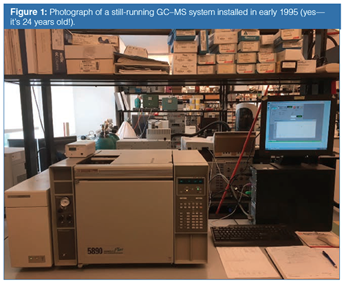
In my own laboratory, I have just renamed a gas chromatography–mass spectrometry (GC–MS) system “The B-52”, shown in Figure 1. Like the famed B-52 aircraft flown by the United States Air Force, it is now older than the graduate students that are operating it. Like a classic car, it has many of the original parts, but some new ones, including the electron multiplier, data system (three times), GC inlet, and the main board. It operates with sensitivity-at least what it was when new. One blessing of GC is that the instruments are generally very rugged and can last for many years, in this case for nearly 25 years. To keep any instrument running well over an extended time, consistent care, maintenance, and troubleshooting are required.
Gas Supplies and Pneumatics
Gas chromatographs are best kept running. This means ensuring a continuous supply of all necessary gases and maintenance of the pneumatics. In a recent “GC Connections” column, Hinshaw reviewed procedures for safely (1) and effectively delivering gases to gas chromatographs. He discusses the special challenges involved in taking down, setting up, and routing the gas supplies to a GC system during a laboratory move. His article is filled with excellent practical tips, safety, and handling advice for setting up a proper gas supply system for gas chromatographs. He discusses sequential setting up and leak testing of a new pneumatic system. In working with any pneumatic system, new or old, an electronic leak detector is a critical tool. Every GC laboratory should have one. They are available from most vendors of GC supplies and consumables.
Once the gas supplies are set up and the system is running, the gases and pneumatics cannot be ignored. On a daily basis, for each gas tank in operation, check both pressure gauges on the regulator. If the tank pressure is getting low, prepare to change the tank. Do not let the tanks “run dry”, as any contaminants that have built up over the many years that the tank has been used by the supplier’s customers (how often do you think the tanks are cleaned?) can be ejected into your instrument. As long as the tank contains some pressure, those contaminants generally remain in the tank. I replace tanks when the tank gauge reads about 100 psi (a brand new full-size helium cylinder contains about 2500 psi). Also be on the lookout for a large decrease in tank pressure from day to day. This is an indication of a major leak in the gas lines between the tank and the GC, which can be found with an electronic leak detector.
When replacing the tank, take care when removing and replacing the regulator. When using copper or stainless steel tubing for regulator connections, take care to avoid overstressing or unduly bending the tubing, as this ultimately can lead to poor connections and leaks. Hinshaw suggests using flexible high-pressure tubing for the regulator connection (1). When purchasing and installing sections of tubing, be sure to use tubing that has been specially cleaned for GC, typically purchased from a GC supplier. Do not use refrigeration tubing from your maintenance department or hardware store. Also be sure to make proper connections using compression fittings, as discussed in GC Connections last year (2).
Scrubbers and filters should be checked and replaced on a regular schedule. A used-up, overloaded scrubber or filter is worse than no scrubber at all. If an adsorbent becomes fully saturated or overloaded, it has no capacity to retain any more contaminants, and any additional contaminants will pass through. Also, it becomes possible for adsorbed contaminants already on the scrubber surface to desorb into the gas chromatograph. Scrubber adsorbents typically last about six months under regular usage. On my GC–MS systems, I generally replace the scrubber adsorbents when doing vacuum system maintenance, as discussed below.
Inlets: The main rule for inlet maintenance is to keep it clean. A review of the troubleshooting guides discussed later in this article reveals that about 75% of all problems in GC occur at or before the inlet. No matter the injection technique, a lot of chemistry happens within the inlet, so regular attention is needed. A dirty inlet is most often suspected in situations where peak shape degrades, typically seen as an increase in tailing.
A split–splitless inlet should be kept heated with gas flowing at all times, even when the system is not in use. “Gas saver” mode, available on most newer gas chromatographs, reduces the gas flow to a few mL/min so additional usage is not excessive. Programmed temperature vaporization (PTV) and cool on-column inlets are generally kept cool when not in use, but carrier gas flow should be maintained. Prior to use, they can be heated to remove any contaminants that may have accumulated while cooled.
The septum should be changed on a regular basis, typically every 25 to 50 injections. With the inlet cooled to change the septum, I also check the glass sleeve and inside the inlet for obvious dirt or contaminants. Use a flashlight to look into the inlet and then remove any pieces of broken column or septum that may be present.
Following inlet maintenance or column trimming, I then re-start the instrument, bring all heated zones to temperature, light the flame ionization detector (FID) (re-start the detector and ensure it is providing a proper signal), and then inject about 5 μL of butane gas from a lighter (split 100:1 or so) and check the peak shape. A poor peak shape indicates a problem with reassembling the inlet, or a bad injection. In general, butane is the best sample for checking overall instrument set up and operation. If you get a bad peak for butane, something is wrong and there is little chance of getting good peaks from your samples.
Columns: The best way to ensure a long column lifetime is to keep the system running with carrier gas flowing. With capillary column flow rates about 1–2 mL/min and gas saver pneumatics, the usage, even in continuous operation, is quite low. The most common carrier gases, helium and nitrogen, are among the most inert of all substances. Hydrogen, while less inert, generally does not react with analytes under the conditions in capillary columns. Combined with a leak-free system, the interior of a capillary GC column, in an operating GC, is one of the most inert environments in all of chemistry.
As the column oven will generally be kept cool between runs or when the system is not in use, it is possible for some contaminants to enter the column and collect, usually at the column head near the inlet. A good procedure for the beginning of the work day is to simply set the oven temperature, with carrier gas flowing and the inlet and detector heated, up and running, to the maximum temperature you use routinely (I use 250 °C), and then get your morning coffee or refreshment. Let it sit at that temperature for 10 to 15 min, then cool it back off to the initial temperature for your methods.
Over time, keep an eye on the chromatograms of your standards, or run a daily test standard. Observe the retention times and peak shapes. Retention times should fall within a narrow window, and peak shapes should be consistent. Increased peak tailing or retention time shifts are indications of problems with the column. Even if the standards consistently pass typical system suitability or other quality tests stated in the method, the beginnings of peak tailing on the peaks for the more active or polar analyte(s) can indicate that the time for column trimming is coming soon. Again, it is easier to predict this in advance and schedule maintenance that involves cooling off the system and turning wrenches into your workflow than to be surprised by a failed system suitability test or seemingly surprise peak tailing or broadening.
Whenever maintenance is completed or a problem is suspected, injecting butane and a check standard, as stated above can confirm that the maintenance was performed and the system restarted correctly. As discussed above, injecting butane can determine whether a problem is with setup of the system or unwanted chemistry in the column or inlet.
Detectors: The basic operating principles of the many detectors for GC are discussed elsewhere (3). Detectors may be broadly classified as ionizationâbased or spectrometryâbased. Some detectors, such as thermal conductivity (TCD), are considered universal; they detect nearly every eluent. Most are considered selective, like FID, which only detects carbon-containing compounds. All detectors are continuously heated to prevent contamination from column effluent, usually to a temperature higher than the highest temperature of the column oven. The first proactive step for proper detector operation is to keep it heated continuously. A cooled detector can easily collect contaminants from the laboratory environment or from the flowing carrier gas.
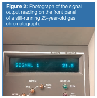
There are several simple “start of the day” checks that your detector is running properly. In short, it should run the same way every day, day in and day out. First, check the output signal. On systems with a keypad, this may be as simple as pushing the “signal” button. Is it the same today as it was yesterday? If it is much different (higher or lower), something has happened or gone wrong. If it is zero, this may also indicate a problem. Few detectors have zero output. If a problem is suspected, check the instrument log book to see if maintenance has been performed.
Figure 2 shows a reading from a system that has been running for about 25 years and is “always” about 20. If it ever reads much higher or much lower, I check the system for problems or changes. In one situation in my laboratory, an analyst had inadvertently substituted a tank of breathing air for our usual FID air supply, resulting in increased background signal; the signal was seen to have risen to about 100.
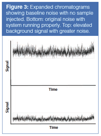
On the data system, check the noise. Many data systems will allow a real-time plot to be displayed without running a sample, or simply start a short run with no sample injected. Observe the real-time plot of the blank data. The baseline should look the same today as it did yesterday, and over time. Expand the plot and look at the amplitude of the rapid noise; it should be the same. If it is greater, this indicates a problem with the detector or electronics. Look at the overall level of the baseline; if it is elevated, this also indicates problems, possibly carrier gas contamination, or overall detector contamination. Figure 3 shows an example of what the noise on a baseline looks like. The bottom plot shows the baseline during a typical run. The top plot shows both larger amplitude random noise and an elevated baseline. Either or both of these occurrences is an indication of a problem with either electronics or contamination. In short, the detector is recording more noise.
Proactive Troubleshooting in GC–MS: In GC–MS, there are several special considerations in proactive troubleshooting. Remember that the MS system is at high vacuum and the high vacuum should be properly maintained over time. A simple daily check is to check both the foreline and high vacuum pressures. Under the same GC column head pressure and column conditions, these should be consistent from day to day. A major change indicates leaks, pump failure, or problems with the GC flow system. All of the routine checks described above can be also used with GC–MS.
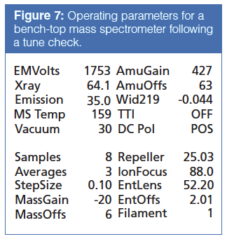
A daily tune file or tune check report provides valuable insight into the operation of mass spectrometric or mass selective detectors. The most common tune is performed using perfluorotributylamine (PFTBA), which has a molecular weight of 671 Da. A typical tune report can include the mass spectrum of PFTBA, specific information about major peaks in the spectrum, usually the base peak at mass 69 and masses 219 and 502, and the operating conditions of the mass spectrometer. Each of these can assist the operator in determining whether maintenance is due. Since the mass spectrometer must be vented and exposed to the laboratory atmosphere, maintenance should be scheduled as far in advance as possible. Do not wait for a breakdown or a poor analysis.
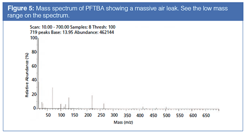
Figure 4 shows a mass spectrum of PFTBA from a daily autotune on a nearly 25-year-old system in the author’s laboratory. The mass spectrum and short report below offer several useful troubleshooting hints. First, note that the mass spectrum looks like a correct mass spectrum for PFTBA. Appearance of additional peaks is evidence of contamination. Air and water are the most common contaminants. They appear as additional peaks in the spectrum at the left (low mass) side, with characteristic signals at m/z 18, 28, and 32. Figure 5 shows a recent spectrum in the author’s laboratory, indicating a major leak that turned out to be at the large o-ring that seals the mass analyzer compartment, following a maintenance procedure. The daily tune check alerted us to the leak. Note that the leak was so massive that both nitrogen and oxygen were themselves fragmented into m/z 14 and 16. The base peak in Figure 5 is m/z 14. The system still appeared to be operating correctly, except for increased noise.
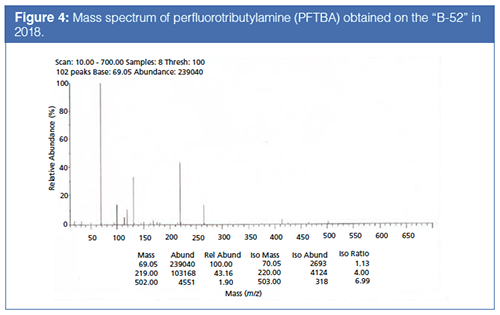
Second, note the relative abundances of 219 and 502 m/z versus 69 m/z and the relative isotope abundances for 70/69, 220/219, and 503/502 m/z. These should all be fairly consistent from day to day. If a big shift is seen from one day to the next or there appears to be a trend, this is an indication that the characteristics of the ionization source are starting to change and cleaning may be necessary in the near future.
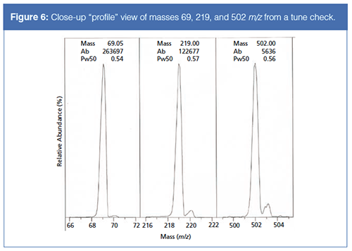
A PFTBA tune check will also focus on the ions at masses 69, 219, and 502 m/z and their accompanying isotopes at M+1. These are used as indicators of low, medium, and highâmass performance. Figure 6 shows close-ups of the 69, 219, and 502 m/z signals. The width and shape of the main peaks should be consistent from day to day. Note the valley between the main peak and the isotope peak. On bench top systems, full baseline resolution from adjacent mass numbers is rare, but there should be a distinct valley. A shallow or non-existent valley is another indication that the ionization source needs to be cleaned. Finally, check the shape of both the main and isotope peaks. If they appear split or “chunky”, this is also an indication that an ionization source cleaning is due soon. Note the split 503 (502 m/z isotope) peak in Figure 6. I would begin to closely monitor this.
Finally, the tune report can provide operating parameters for the various electronic elements in the ionization source, mass analyzer, and detector. The most important of these is the electron multiplier voltage, which, in Figure 7, is 1941 V. I monitor this on a daily basis. A higher electron multiplier voltage means that the ionization source and mass analyzer are providing fewer ions for the electron multiplier to detect, again an indication that cleaning may be necessary. If it starts to increase (it has been slowly increasing over the past two weeks, in fact), I begin to consider cleaning the ionization source. Based on this tune report, while I am not ready to vent the system and clean the ionization source today, I expect to schedule that maintenance in the next few weeks, depending on my sample throughput and work schedule.
Additional preventative steps should be taken with the mechanical components. All GC–MS systems have a roughing pump for which the pump oil should be replaced on a regular schedule, generally every six months or one year. They may also have filter pellets on the exhaust, which should also be replaced when the oil is changed. Turbomolecular pumps, which provide high vacuum, are maintenance-free but strange noises are an indication of imminent failure and replacement is a capital expense. Some GC–MS systems, like the one highlighted in this article provide high vacuum using a diffusion pump, which has no moving parts, but contains oil that should be changed on a regular schedule, typically annually. In short, have a regular maintenance schedule for the mechanical parts of your GC–MS system.
Troubleshooting Tools, Guides, and Resources: Numerous guides and books on troubleshooting are available. The most comprehensive book was published by Rood in 2007 (4). Most of the classic texts on GC include chapters related to troubleshooting and optimization of instrumentation, columns, and detectors; one example is referenced here (5). Simpleâtoâfollow troubleshooting guides are available online from many column and instrument vendors. As I suggested last year, simply go to the website of your column or instrument manufacturer and enter “GC Troubleshooting” into the search function. A few tries with major vendors will quickly lead to a useful (and free) guide.
Gas chromatography is an extremely reliable and robust technique. However, over time, all gas chromatographers eventually become adept at troubleshooting. Proactive troubleshooting, which emphasizes prevention rather than a cure, can save gas chromatographers time, effort, and money. Some examples of daily and routine qualifications are to check pressures and flows in your pneumatic system, check for leaks whenever a maintenance procedure is performed, keep the GC heated and running with all gases flowing at all times, check the signal outputs on the detector, check the tune on the mass selective detector (MSD) on a regular basis, and have standards available for checking the column. Like maintaining your car, proactive troubleshooting can enable a GC or GC–MS to run effectively for not just years, but for decades.
References
- J.V. Hinshaw, LCGC Europe31(9), 500–503 (2018).
- N.H. Snow, LCGC Europe31(1), 28–34 (2018).
- ChromAcademy, “GC Detectors” https://www.chromacademy.com/gc-training.html (Accessed November 2018).
- D. Rood, The Troubleshooting and Maintenance Guide for Gas Chromatographers (John Wiley and Sons, New York, USA, 4th ed., 2007).
- H. McNair, and J. Miller, Basic Gas Chromatography (John Wiley and Sons, New York, USA, 2nd ed., 2009).
Nicholas H. Snow is the Founding Endowed Professor in the Department of Chemistry and Biochemistry at Seton Hall University, USA. He is also the university’s Director of Research and Adjunct Professor of Medical Science. During his 30 years as a chromatographer, he has published more than 60 refereed articles and book chapters and has given more than 200 presentations and short courses. He is interested in the fundamentals and applications of separation science, especially gas chromatography, sampling, and sample preparation for chemical analysis. His research group is very active, with ongoing projects using GC, GC–MS, two-dimensional GC, and extraction methods.
“GC Connections” editor John V. Hinshaw is a Senior Scientist at Serveron Corporation in Beaverton, Oregon, USA, and a member of LCGC Europe’s editorial advisory board. Direct correspondence about this column to the author via e-mail: LCGCedit@ubm.com

University of Rouen-Normandy Scientists Explore Eco-Friendly Sampling Approach for GC-HRMS
April 17th 2025Root exudates—substances secreted by living plant roots—are challenging to sample, as they are typically extracted using artificial devices and can vary widely in both quantity and composition across plant species.
Thermodynamic Insights into Organic Solvent Extraction for Chemical Analysis of Medical Devices
April 16th 2025A new study, published by a researcher from Chemical Characterization Solutions in Minnesota, explored a new approach for sample preparation for the chemical characterization of medical devices.

