Peak Fronting . . . Some of the Time
LCGC North America
Why do some peaks front when others don't - in the same method?
Why do some peaks front and others don't in the same method?
I often get asked how I come up with the topics that are covered in my "LC Troubleshooting" column every month. Most of the time, the source is either questions I receive via e-mail (see instructions at the end of this column if you have a question to ask me) or in live classes that I teach around the world. This month, the topic originates in the latter category. One course attendee had observed a problem with her liquid chromatography (LC) method in which a peak fronted. Most of us are familiar with tailing peaks, in which the peak rises from the baseline rapidly, but returns to the baseline more slowly, resulting in a distorted peak, where the second half of the peak is broader than the first half, forming a "tail." In the present case, injections of the reference standard gave normal, nearly symmetric peaks, but when the samples were injected, the peaks rose more slowly from the baseline than normal, resulting in a fronting peak, where the first half of the peak is broader than the second half. The question, of course, was what was going on and how to correct the problem.
Divide and Conquer
One of the troubleshooting principles that I frequently mention is what I call the "divide-and-conquer" technique. This is simply the process of sequentially dividing the problem into (usually) two major parts by changing some variable and observing the result. The goal is to find changes that either do or do not make a difference in the observed problem. This helps to eliminate possible causes of the problem. As we go through a series of such steps, we progressively eliminate potential problem sources until we are left with the root cause of the problem. For example, in the first step, we may eliminate half of the possible causes, in the second, half of the remaining causes, and so on. It doesn't take long to be left with just one or two things that may have to be sorted out to correct the problem.
A second principle of troubleshooting is to use the scientific method and change just one variable at a time. In this manner, we will know which variables influence the problem and which do not. Often it is tempting to change several items together, just to get the problem solved and get back to work, but in the long run, this approach doesn't help us identify the real problem source so that we can avoid or minimize future problems. For example, for a problem observed in the chromatogram, we might change the column, guard column, in-line filter, and make a fresh batch of mobile phase. This may fix the problem, but it does not get to the root cause of the problem — for example, use of the wrong pH for the mobile phase — and therefore may waste money (we may have discarded a perfectly good column) and invite future problems (perhaps we should add a step to double-check the mobile-phase pH).
Usually, we apply the divide-and-conquer technique along with changing just one thing at a time during troubleshooting. This may be a conscious or subconscious process. Let's try this approach with the present problem.
What's Different and What's the Same?
The first round of troubleshooting has already been done for us; the remaining ones we'll have to speculate on, but they will help to define experiments that will help us identify the root cause of the problem. We know that injection of the reference standards results in acceptable peak shapes, but sample injections give fronting peaks. We also know that the two injection types consistently give distinctly different results (our first divide-and-conquer experiment). What do these two items have in common, and what is different between them?
Both the standards and samples use the same mobile phase, instrument, and column, so it is unlikely that any of these items is at fault. As a side observation, peak tailing is a much more common problem with LC separations. Tailing is most commonly attributed to unwanted secondary interactions between the analyte molecule and the column. Usually this results from strong interactions between acidic silanol groups on the column packing and basic functional groups on the analyte. When this happens, usually the analyte in both the reference standards and samples gives the same tailing peak shape. The different peak shape between the two cases in the present example is further evidence that the column is not at fault. The most common cause of peak fronting that is observed today is the collapse of the column bed, but when column collapse occurs, both standards and sample will generate the same fronting peak shape, so we know this is not the source of the current problem. However, because column collapse is the most common cause of fronting peaks, it is covered briefly at the end of the present discussion.
The present method was used to determine the potency, or concentration of the analyte, in a formulated drug product. We will assume that during method development and validation it was found that acceptable precision and accuracy were obtained with the reference standard prepared in a water–organic solution, as often is the case for this type of method. The most likely source of the problem is something that is different between the standard and the sample. Let's make a list of some possible differences, then we can devise experiments to isolate the root cause. Here are some possibilities:
- injection volume
- aqueous–organic ratio of the injection solvent
- pH of the injection solvent
- presence or absence of matrix components
- presence or absence of other analytes.
I'm sure I've missed something obvious in this list — you readers are always helpful to point this out! Let's look at each item in turn.
Injection Volume
Injection of too large a volume can distort peaks, producing fronting, tailing, or split peaks, often worse for peaks that are eluted near the front of the chromatogram. Injection volume problems often are made worse if too much of too strong a solvent is injected (see next item). A simple rule of thumb to determine the maximum injection volume is that up to ~15% of the volume of the first peak of interest can be injected if the sample is dissolved in the mobile phase. I'm not sure what column size or packing particle size was used for the present case, but I have shown some estimates for various column configurations in Table I that can be used for comparison. For the various columns shown, these assume a realistic column plate number and a retention factor (k) of 1 (as is usual for such presentations, I have rounded values for clarity). For example, a 150 mm × 4.6 mm column packed with 5-µm diameter particles will produce a k = 1 peak with a volume of ~126 µL, corresponding to a maximum injection volume of ~19 µL. Contrast this with a 50 mm × 2.1 mm, 2-µm particle column, where the corresponding injection volume is only ~1.4 µL. Usually, but not always, the injection-volume effects will be the same for standards and samples, so I do not suspect that injection volume alone is the cause of the problem. However, the experiment is simple — just reduce the injection volume by a factor of two or more and see if the peak shape improves.

Table I: Estimated peak and maximum injection volumes for various columns
Aqueous–Organic Ratio of the Injection Solvent
The estimates of maximum injection volume just mentioned assume that the injection solvent (sample diluent) is the mobile phase or a weaker solvent. For reversed-phase separations, this means the injection solvent can have no larger organic content than the mobile phase for the referenced injection volumes. Even if the injection volume is smaller than that referenced in Table I, it may be too large if there is more organic solvent in the sample diluent than in the mobile phase. Furthermore, different aqueous–organic ratios used for the standard and sample injections can be the source of the problem. My first guess is that the sample and standard diluents are different, and this, perhaps in combination with the injection volume, is the problem source. It is common to prepare reference standards in a highly aqueous solution. For example, the initial dilution of the standard may be in a small volume of methanol or acetonitrile to ensure that it is fully dissolved. Then subsequent dilutions are made with water or buffer. As a result, the injected standard may be in <1% organic solvent. In contrast, the sample may contain significantly more organic solvent because of the sample preparation scheme. The test in the present case is simple. It may be inconvenient to reduce the organic content of the sample diluent, but by rediluting the reference standard with solutions containing the same percentage of organic solvent as the sample, you will produce standards and samples in equivalent diluents. If the newly diluted standards front, you will have identified the problem source. Reducing the injection volume or modifying the sample preparation scheme to result in a more aqueous final sample should fix the problem. For example, if 50% methanol–water is used to prepare the sample to fully dissolve it, it may be possible to initially dissolve the sample in one fourth of the volume of 50% methanol, then adjust the sample to the final volume with water for a 12.5% methanol–water injection.
pH of the Injection Solvent
Ideally, the injection solvent pH should be adjusted to match the pH of the mobile phase. Also, the pH of the diluent for the reference standard and sample should be the same. Often an unbuffered or weakly buffered diluent will not be a problem if the injection size is sufficiently small so that the pH of the injection solvent is immediately shifted upon injection by a properly buffered mobile phase. But if the pH of the standards or samples do not match the mobile phase, try the experiment and match the mobile-phase pH to see if the problem is corrected. As with the organic solvent in the injection, pH effects may be exacerbated by injections that are too large.
Presence or Absence of Matrix Components
A final product usually contains "inert" ingredients that facilitate shelf life, sample stability, dissolution, or other desirable characteristics of the sample. Often these components of the matrix contain buffers or acidic or basic components. Such components, when dissolved or extracted, can affect the final pH of the sample solution, making it different from the reference standard solution. This should be easy to check by determining the pH of the respective solutions. If they are different, adjustment of the sample solution to match the reference standard may be necessary. Similarly, other matrix components can influence the chromatography. It may be possible to obtain each of the excipients or matrix components individually and formulate experimental sample solutions deficient in one or more components to determine if this is the problem source.
Presence or Absence of Other Analytes
Just as matrix components can affect the chromatography, it is possible that other analytes in the sample may cause problems. I do not suspect that this is the case, because the reference standard should contain all the analytes. But if it does not, it would be easy to check this by combining all the analytes in a single reference standard solution.
The Magic Combination
You can see from the discussion above that the different potential error sources often influence each other. For example, if you inject a small enough volume, you can inject just about any sample without problems, no matter how incompatible the solution appears to be. The mobile phase often will dissolve, adjust, or disperse problem conditions or components if their concentration is small enough. All of these potential problem sources point to the importance of robustness testing during method development and validation. It is a good idea to check the influence of the variables you can adjust — injection volume, organic solvent concentration, analyte concentration, pH, and so forth — both alone and in combination to be sure the method will produce acceptable results when one or more variables are changed slightly. The analogy is if you are standing on a cliff to watch the ocean. There is a much greater chance of falling off because of a wind gust or an unstable surface if you are right at the edge of the cliff. You can see almost as well if you stand back from the edge, and you are much safer. In a similar manner, you need to find the "edge of the cliff" for your methods and adjust conditions so they are not too close to this zone of potential disaster.

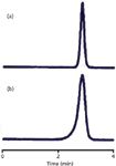
Figure 1: Peak fronting: (a) Normal peak shape; (b) fronting after ~500 injections. See text for details.
Classical Peak Fronting
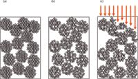
As I mentioned earlier, the most common cause of peak fronting is a physical degradation of the packing bed inside the column. This is fairly rare today, because most columns are packed much better and are more stable than those from the past. With some of the older, low-purity, type-A columns that were predominant before the mid-1990s, a physical shock to the column, such as dropping it or even pressure pulses during injection, could eventually cause the column to collapse. The chromatograms of Figure 1 show what might happen. These are from a method in our laboratory that used a pH and column temperature that were significantly in excess of those recommended for the column. After approximately 500 injections, the peak shape changed from the normal peak of Figure 1a to the fronting peak of Figure 1b. This affected all chromatograms — sample and reference — and could not be reversed. The cause is illustrated in the cartoon of Figure 2. In Figure 2a, a normal column is shown, packed with particles. These particles can be thought of much like popcorn balls, where the final particle is made up of many smaller particles, and the spaces between the smaller particles are the pores in the packing. Such particles and the packed bed are very stable, often for thousands of injections, if the mobile-phase conditions are not too aggressive. For most C18 columns, this means temperatures of ≤70 °C and pH ≤ 8. There are columns that will withstand more rigorous conditions and some are more fragile. In this case, the column limits were 40 °C and pH 7, with a warning that the combination of conditions near the limits could severely limit the column lifetime. The column was operated at 70 °C and pH 9, and these conditions gradually dissolved the column. In Figure 2b, you can see that some of the tiny particles have dissolved, but the overall matrix is still stable. But at some point, enough of the silica has dissolved that both the individual particles and the packing bed become very fragile. A pressure pulse from the injector cycling may be enough to cause the collapse of a particle; then a chain reaction starts and the column bed can settle, as in Figure 2c. If the top of the bed is distorted, as is shown in Figure 2c, the injected sample stream (arrows) reaches the top of the column at different points, distorting the flow profile. Because some of the molecules flow farther down the column before they start moving chromatographically, they get a head start over the others and result in a fronting peak. There is no fix for this problem other than replacing the column and changing conditions to prevent it from happening in the future.

Figure 2: Illustration of column collapse: (a) new column; (b) column after partial dissolution; (c) column after collapse, with the arrows showing the injection flow stream. See text for details.
Conclusions
We have seen that, although peak fronting most commonly results from column collapse, there are other potential sources. The best approach is to do a mental analysis of the potential causes, as we did here, then judiciously devise experiments to help prove or disprove your hypothesis of what caused the problem. After the problem source is identified and confirmed, you can figure out how to adjust the experimental conditions to eliminate or minimize the problem.
John W. Dolan "LC Troubleshooting" Editor John Dolan has been writing "LC Troubleshooting" for LCGC for more than 30 years. One of the industry's most respected professionals, John is currently the Vice President of and a principal instructor for LC Resources, Walnut Creek, California. He is also a member of LCGC's editorial advisory board. Direct correspondence about this column via e-mail to John.Dolan@LCResources.com

John W. Dolan

Extracting Estrogenic Hormones Using Rotating Disk and Modified Clays
April 14th 2025University of Caldas and University of Chile researchers extracted estrogenic hormones from wastewater samples using rotating disk sorption extraction. After extraction, the concentrated analytes were measured using liquid chromatography coupled with photodiode array detection (HPLC-PDA).
Polysorbate Quantification and Degradation Analysis via LC and Charged Aerosol Detection
April 9th 2025Scientists from ThermoFisher Scientific published a review article in the Journal of Chromatography A that provided an overview of HPLC analysis using charged aerosol detection can help with polysorbate quantification.
Removing Double-Stranded RNA Impurities Using Chromatography
April 8th 2025Researchers from Agency for Science, Technology and Research in Singapore recently published a review article exploring how chromatography can be used to remove double-stranded RNA impurities during mRNA therapeutics production.


