Optimizing Splitless Injections in Gas Chromatography, Part I: What It Is and What Happens When We Inject


In gas chromatography (GC), injecting samples is seemingly among the simplest steps in the analysis. For trace quantitative analysis, the splitless technique is most used as an inlet capable of performing both split and splitless injections, and is standard equipment on most gas chromatographs. In this and upcoming installments, we take a closer look at splitless injection, which is not as simple as it seems. Beginning with the syringe and autoinjector, the sample is subjected to passage of the syringe needle through a septum, ejection from the needle, deposition onto a surface in the inlet, evaporation, transfer to the column, condensation of the sample vapor in the column, and finally, temperature programming. All of this typically occurs in the first 30–60 s of the separation. If unwanted chemistry occurs in any of these steps, the injection may not be reproducible enough for precise quantitation. As we proceed, we will discuss some straightforward optimizations that can be performed to assist in obtaining reproducible splitless injections.
The inlet is the most critical and least understood part of a gas chromatograph. Although injecting liquid samples seems so simple, the processes involved in transferring samples from a syringe into a capillary column are very complex. Even the terminology confuses many chromatographers. In this article, and in the best usage, the term inlet refers to the device mounted on the gas chromatograph into which a syringe needle penetrates when a sample is injected. Inject (as a verb) and injection (as a noun) refer to the process of transferring a sample from a syringe or valve into the inlet. An injector refers to a device external to the gas chromatograph, usually an autoinjector, but sometimes the chromatographer themself, that performs the act of injection. We often use combined terms, such as split injection, splitless injection, or on-column injection to describe the entire process.
An inlet capable of being used to perform both split and splitless injections is standard equipment on nearly all commercial laboratory gas chromatographs. When reporting results or writing methods, be careful to accurately describe the inlet and technique used. Very often, when reviewing literature, I see the injection technique or inlet described as “split/splitless” rather than “split” or “splitless.” The inlet can only do one technique at a time, split or splitless, not both.
Before considering the details of splitless injection, it is useful to briefly discuss its origin. In his classic book, Grob, who performed the work, describes this in detail. In referring to this book, we see that split and splitless injections and inlets are complex enough to require an extensive text (1). The split technique came first, and was among the original techniques used for injecting samples at the inception of capillary gas chromatography.
Figure 1 shows a schematic diagram of the inlet used for split and splitless injections, captured from LCGC International’s online learning platform, ChromAcademy (2). Ideally, split injection involves setting up the inlet so that the injected sample is rapidly vaporized inside the glass sleeve, and mixed with carrier gas at a high flow rate. From the glass sleeve, there are two ways out: the column, which has a low flow rate, for example, 1 mL/min, and the split vent, which has an adjustable, usually high, flow rate, for example, 50 mL/min. Ideally, in this example, a 50:1 ratio of sample out the split vent to sample in the column is generated.


Figure 1: Schematic diagram of a split-splitless inlet.
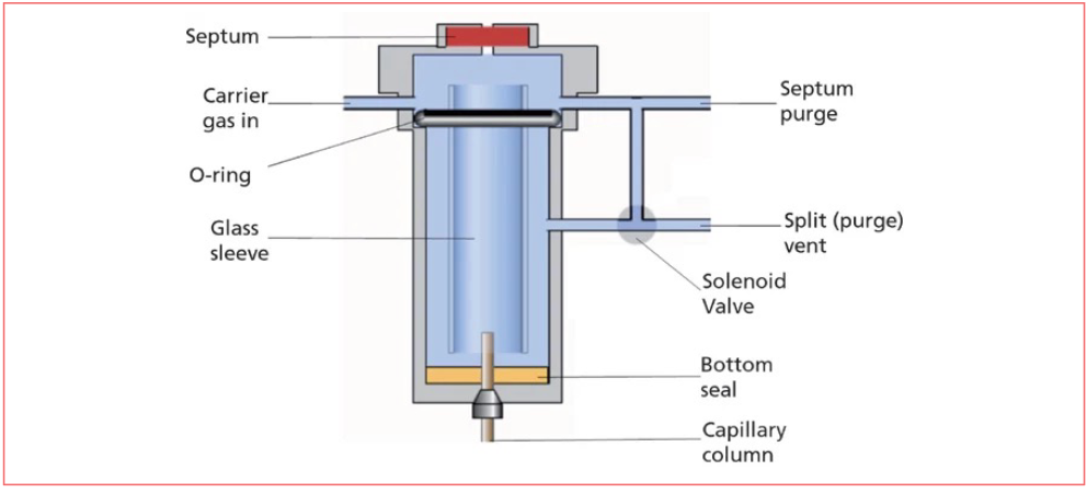
Inlet splitting was thought to be necessary from the inception of capillary gas chromatography, as it was believed that too much injected solvent would cause the stationary phase coating to strip from the inside walls of the column. Note that today’s fused silica columns with chemically bonded and crosslinked stationary phases did not exist then. Stationary liquid phases were coated on the inside walls of the capillary, with the capillary usually being made from glass. Columns of the day were much more fragile, difficult to manufacture, and expensive than they are today.
The first splitless injection was performed by accident in the late 1960s (3). At that time, a simple way to save carrier gas but keep the instrument running during downtime, today’s “gas saver” feature, was to simply close the split vent when the instrument was not running. Most injections at that time were performed manually, and most data analysis was done using a strip chart recorder. Modern autoinjectors and data systems did not exist. Imagine then, injecting a sample and starting the recorder, but not opening the split vent beforehand. You look down at the instrument about a minute later, realize your mistake, and open the vent.
At this point, you expect that your analysis, and possibly your column, are ruined. The baseline is “maxed out” at the top of the paper, and it does not seem to come down. You are hoping that the recorder will eventually return to baseline, and that your stationary phase is still in the column. You step away for a short time, and return to a pleasant surprise: a pretty normal-looking chromatogram, but with a big solvent peak.
The signal returned to baseline relatively quickly, and the stationary phase was apparently not damaged. Interestingly, the analyte peaks are tall and mostly symmetrical; we would call these good peaks. Even this simple story describes what a splitless injection and inlet are, and why we do them. Splitless is so interesting and useful because it uses the same hardware as split, so a split/splitless inlet is really two inlets in one. The split inlet is good for routine analysis of relatively high concentration (ppm and higher) samples and for complex mixtures requiring a very fast injection process and sharp peaks. The splitless inlet is useful for lower concentration analysis (ppm and lower). Both inlets have excellent performance in quantitative analysis when operated correctly. We will now explore some of the lessons from the initially surprising results of the first splitless injection seen in our story.
This story, undoubtedly embellished (as legends often are), demonstrates the key features of the splitless injection technique and inlet, teaching several lessons about good chromatography and science. As described, there are several variables involved in setting up for a splitless injection. For the inlet, we consider the inlet temperature and pressure, carrier gas flow rate, purge valve time (how long the split vent is kept closed following the injection), and geometry and surface chemistry of the inlet liner.
In the story, it was likely 1 min or more from the injection to the opening of the split vent, so it can be surmised that the analytes took the full 1 min to travel through the inlet. Yet the peaks we see in our chromatograms are much sharper than one minute. This suggests that there must be a focusing mechanism that happens in the column. Additional variables must therefore include column dimensions, stationary phase film thickness, the chemical nature of the stationary phase, sample solvent, and analytes.
Finally, in the story, the liquid sample was manually injected using a syringe. Especially in the days of manual injection, proper syringe handling techniques were required for reproducible injections. When I started graduate school with Professor McNair at Virginia Tech, our first lesson on injecting was to make ten consecutive manual injections of a simple solvent mixture with a less than 2% relative standard deviation on the peak height. Even with a short 3-min run time, this took all day for me to achieve. Today, we use fast autoinjectors, but the syringe and its operation remain a critical part of the injection process.
As we now see, the injection process includes several steps, beginning with drawing a liquid sample into the syringe, followed by inserting the syringe into the inlet, usually through a septum, depressing the plunger to eject the sample into the inlet, vaporizing the sample in the inlet, mixing it with the carrier gas, and transferring the sample vapor-carrier gas mixture into the column. For now, let’s assume that we are using a fast autoinjector to inject a 1 µL liquid sample with a typical 10 µL syringe, the most common configuration. Let’s assume for now that the autoinjector does its job, rapidly and quantitatively, injecting the sample into the inlet.
One challenge in thinking about the inlet is that we cannot see what is going on inside the glass liner when the sample is injected. There is an excellent set of videos that accompany the Grob text mentioned earlier, produced using an all-glass inlet that clearly show what happens under different injection conditions. Using some simple tools likely available in your kitchen, you can simulate what really happens in the inlet immediately following injection.
Figure 2, reprinted from an earlier installment of “GC Connections,” shows the result of a very simple experiment (4). Originally, I termed this the “This is your brain on drugs” experiment, after a similar and famous public service television announcement in the United States (5). To repeat this experiment, obtain a heavy cooking pan, such as a cast iron skillet, a teaspoon, and some water. Heat the skillet on the stove over high heat, and make it hot. Using the spoon, pour a small amount of water into the skillet, and observe the results.

Figure 2: Result of about 1 teaspoon of water being added to a cast iron skillet. Full evaporation required appromixately 10 s. Note that some droplets are colored due to contamination on the skillet surface. Reprinted from reference (4) with permission of the author.
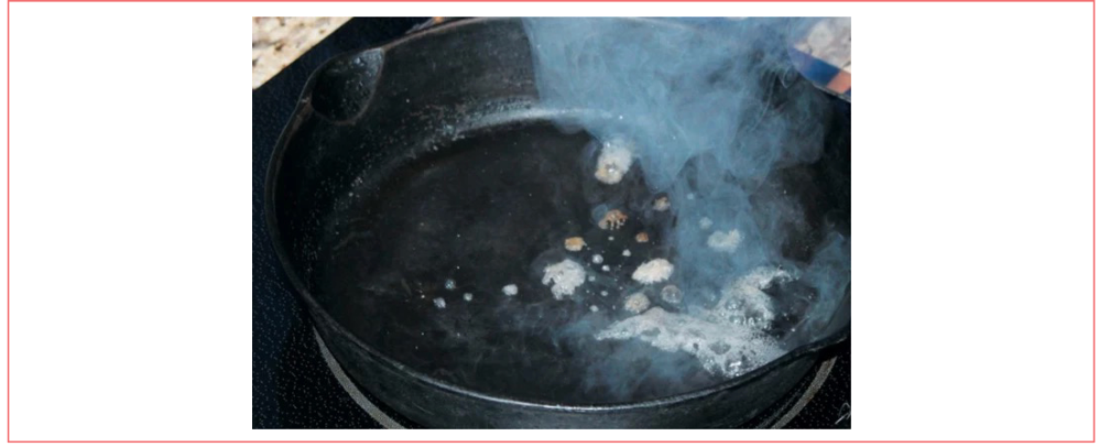
In Figure 2, we see that, even though the thermal mass of the skillet is much greater than the water and the skillet is heated well above the boiling point of water, the water does not immediately evaporate; it instead appears to dance around the surface of the skillet for several seconds or more before it all evaporates. This behavior when a small amount of liquid is placed on a hot surface has significant implications for liquid sample injections in gas chromatography, and it points out some common misconceptions about injections that are commonly described in textbooks and short courses.
Misconception #1: The liquid sample evaporates instantaneously upon injection. From Figure 2, we see that the liquid does not instantly evaporate. Remember that gases are very strong insulators; think about the double- and triple-paned glass windows commonly used in cold climates. The gas space between the panes provides excellent insulation. The insulating properties of gas within the inlet prevent the heated surfaces from quickly transferring that heat to the sample. Reality: liquid samples require several seconds or more to evaporate.
Misconception #2: The liquid sample evaporates quickly when it lands on the heated surface. The dancing water droplets seen in Figure 2 show that, even when the liquid strikes the surface directly, it still does not immediately evaporate. When the liquid strikes the surface, the liquid touching the surface evaporates, leaving a small vapor space between the surface and the rest of the droplet. This then insulates the rest of the droplet, with movement of this heated vapor causing the droplet’s movement. Reality: The liquid evaporates slowly from the surface.
Misconception #3: Mixing between the carrier gas and the sample vapor is rapid and homogeneous. Under splitless conditions, inlet liner flow is slow. With a typical volumetric flow rate of 1 mL/min and an inlet liner volume of about 1 mL, approxmately 1 min is required for the full liner volume to be swept by carrier gas. Therefore, the evaporation and mixing process is slow and possibly non-homogeneous, especially if the inlet is dirty. Reality: Evaporation and mixing with carrier gas in the inlet are slow.
These realities demonstrate some characteristics of your own splitless inlets that you may have observed. First, the inlet is heated to facilitate sample evaporation. Second, the glass inlet liner most likely contains obstructions, baffles, or glass wool to provide greater heated surface area for evaporation and to prevent injected liquid from shooting straight to the bottom of the inlet. Third, the injection is slow, so there must be some focusing processes that occur after the sample reaches the column; this is why nearly all methods including splitless injection include temperature programming. In future installments, we will further explore setting up the inlet and column conditions for successful splitless injections. We will also share special techniques that can be used if traditional injection does not provide adequate peak shapes or quantitative reproducibility.
A splitless inlet is simultaneously simple and complex. Setting up the inlet and performing the injection is quite simple. However, there is much background chemistry going on that can become complex, which can be one of the major and most common causes of reproducibility and performance problems in gas chromatography.
References
(1) Grob, K. Split and Splitless Injection for Quantitative Gas Chromatography: Concepts, Processes, Practical Guidelines, Sources of Error; John Wiley & Sons, 2007.
(2) “Split/Splitless Injection for Capillary GC.” https://www.chromacademy.com/channels/gc/instrumentation/split-splitless-injection-for-capillary-gc/ (accessed 2024-08-15)
(3) Grob, K.; Grob, G. Splitless Injection on Capillary Columns, Part I. The Basic Technique; Steroid Analysis as an Example. J. Chromatogr. Sci. 1969, 7 (10), 584–586. DOI: 10.1093/chromsci/7.10.584
(4) Snow, N. H. Split, Splitless and Beyond – Getting the Most from Your Inlet. LCGC North Am. 2018, 36 (7), 448–454.
(5) White, M. C. “‘This Is Your Brain on Drugs,’ Tweaked for Today’s Parents.” The New York Times, August 7, 2016. https://www.nytimes.com/2016/08/08/business/media/this-is-your-brain-on-drugs-tweaked-for-todays-parents.html (accessed 2024-08-15)
About the Author

Nicholas H. Snow is the Founding Endowed Professor in the Department of Chemistry and Biochemistry at Seton Hall University, and an Adjuncy Professor of Medical Science. During his 30 years as a chromatographer, he has published more than 70 refereed articles and book chapters and has given more than 200 presentations and short courses. He is interested in the fundamentals and applications of separation science, especially gas chromatography, sampling, and sample preparation for chemical analysis. His research group is very active, with ongoing projects using GC, GC-MS, two-dimensional GC, and extraction methods including headspace, liquid-liquid extraction, and solid-phase microextraction. Direct correspondence to: LCGCedit@mmhgroup.com


, Up-To-Date Greenness, and Whiteness Set of Tools for Evaluation of a Sustainable RP-HPLC Method for Regulated Products")


Fundamentals of Benchtop GC–MS Data Analysis and Terminology
April 5th 2025In this installment, we will review the fundamental terminology and data analysis principles in benchtop GC–MS. We will compare the three modes of analysis—full scan, extracted ion chromatograms, and selected ion monitoring—and see how each is used for quantitative and quantitative analysis.


Study Examines Impact of Zwitterionic Liquid Structures on Volatile Carboxylic Acid Separation in GC
March 28th 2025Iowa State University researchers evaluated imidazolium-based ZILs with sulfonate and triflimide anions to understand the influence of ZILs’ chemical structures on polar analyte separation.