A NanoLC–MS Primer for Expression Proteomics: Part II
LCGC North America
This is the second installment of a two-part series on the practical aspects of configuring and operating a nano liquid chromatography-mass spectrometry (LC-MS) system.
This is the second installment of a two-part series on the practical aspects of configuring and operating a nano liquid chromatography–mass spectrometry (LC–MS) system. This installment addresses tubing and fittings. Chromatographers accustomed to conventional LC systems will need to adapt to operation at nanoliter-per-minute flow rates, and this month's column presents options and guidelines for connecting the components of an LC–MS system.
The sensitivity requirements for performing protein identification using liquid chromatography–mass spectrometry (LC–MS) in expression proteomics studies requires the use of capillary high performance liquid chromatography (HPLC) columns coupled to nanospray ionization sources. This two-part series of "Directions in Discovery" addresses the practical considerations in assembling the components of a nanoLC–MS system and operating at nanoliter-per-minute flow rates. In the first installment (1), we reviewed solvent delivery systems, splitters, autosamplers, trapping systems, and capillary HPLC columns for nanoLC–MS. In this second installment, we discuss the selection and assembly of capillary tubing with nanoLC columns, fittings, and unions. We also explore some validation issues in using nanoLC–MS for proteomics.
Tubing and Fittings
A consequence of using capillary HPLC columns at nano flow rates is the requirement for reducing the volumes in transfer lines and fittings. To accomplish this, the standard 0.005-in. (0.13 mm) i.d. or 0.010-in. (0.25 mm) i.d. tubing used in conventional HPLC systems must be replaced with capillary tubing. The most popular capillary dimensions are 50-μm i.d. × 360-μm o.d. Using 25-μm i.d. tubing will reduce delay volumes fourfold compared with 50-μm i.d. tubing, but with a greater risk of plugging. In addition, because pressure varies inversely with the fourth power of the diameter, a length of 25-μm i.d. tubing will exhibit a 16-fold increase in operating pressure contributed by tubing resistance relative to that of the same length of 50-μm i.d. tubing. However, this increase might be small compared with column pressure, the major contributor to overall system pressure. Finally, tubing length should be kept to an absolute minimum to reduce delay volumes.
Capillary tubing in the dimensions mentioned previously is available in three materials: fused silica, PEEK, and Teflon PFA HP Plus (DuPont, Wilmington, Delaware). The differences between these tubing materials include their pressure holding capacity, temperature range, and chemical compatibility. The relative ease of use for these types of tubing can vary, which is discussed in the following section on cutting tubing. We recommend users explore the differences between these tubing materials to determine which is best for a particular application.
Conventional HPLC pumps, injectors, and columns are designed to be connected using 1/16-in. o.d. tubing. To accommodate the smaller outer diameter of capillaries, three strategies are available (2): use of specialized ferrules with capillary-sized throughholes, use of tubing sleeves, and use of PEEKsil tubing (SGE Inc., Austin, Texas). While these methods provide ways to adapt capillary tubing to a larger world, special attention while making connections is still important to help avoid carryover, band broadening, and delay volumes. In nanoLC–MS, an improperly connected fitting postcolumn means a separated peptide could be caught in an unswept mixing chamber before it reaches the MS detector!
Specialized ferrules: Specialized ferrules have outer geometries similar to those of conventional fittings, but with smaller through-holes compatible with 360-μm i.d. capillary tubing (Figure 1). They also have an extended 1/16-in. o.d. "nose" to reduce dead volume in the connection. Specialized ferrules have three drawbacks. First, they must be machined from specialized materials, which increases their cost relative to conventional ferrules. Second, the fixed ferrule geometry might not perfectly match the internal geometry of all fittings due to variations in the length of the tubing pocket. This can result in leaks or dead volume (which causes carryover and band broadening) because the tubing will not be properly seated in the receiving port. Third, they might not seal well at elevated pressures.
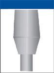
Figure 1: Example of a specialized ferrule for capillary tubing. Reproduced from reference 2 with permission from Upchurch Scientific (Oak Harbor, Washington).
Tubing sleeves: Sleeves allow conventional ferrules to be used with fused-silica capillaries. Tubing sleeves have an outer diameter of 1/16 in., which allows them to fit into standard receiving ports (Figure 2). The sleeve acts as a "jacket" that moves independently of the ferrule, compensating for variable tubing pocket depths. This is a strong advantage over specialized ferrules. In addition, the extrusion process used in sleeve manufacture provides a more concentric connection than custom-drilled ferrules, for more accurate tubing–through-hole alignment. Finally, the sleeve provides structural support to prevent damage to the capillary tubing.
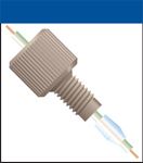
Figure 2: Capillary tubing sleeve. Reproduced from reference 2 with permission from Upchurch Scientific.
PEEKsil tubing: PEEKsil is polymer-sheathed fused-silica tubing with outside diameters of 1/32 and 1/16 in. (Figure 3). The sheathing polymer is polyetherether ketone (PEEK), which has excellent mechanical strength, good sealing properties, and is resistant to almost all HPLC solvents. Because it has the same outside diameter as standard HPLC tubing, it can be used with conventional nuts, ferrules, and fittings. It also has superior sealing properties at high pressure compared to custom-drilled ferrules. The major limitation of PEEKsil tubing is that it cannot be cut using standard laboratory equipment, and must be ordered precut from the vendor. It is available in 5–50 cm lengths in various increments and can be ordered in custom lengths from some vendors.
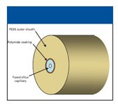
Figure 3: PEEKsil tubing.
We have evaluated all three approaches for making capillary connections, and found PEEKsil to be the most robust in spite of the inconvenience of using precut lengths. One caution in assembling capillary connections is the use of care in tightening the connection. Overtightening can cause fracturing of the fused silica, and the microparticles generated by fracturing can cause internal scoring of injector valves and plugging of columns. Our practice is to use winged "finger-tight" fittings, and give the tubing a gentle tug after assembly to confirm that the ferrule is seated.
Cutting Capillary Tubing
To obtain leak-free connections, minimize dead volume, and avoid plugging, it is important that fused-silica tubing be cut to obtain a flat surface free of debris. Three techniques are used to cut fused-silica tubing: scoring with a ceramic tile, scoring with a diamond scribe, or circumscribing with a cutting tool.
Scoring with a ceramic tile: In this procedure, the polyimide coating of the capillary is scored with a piece of ceramic tile, then bent or pulled to effect the break. This technique long has been used in cutting fused-silica tubing for capillary electrophoresis, and it is the most economical method. However, it can fail to yield a clean, straight cut and can result in shredding of the polyimide or shattering of the fused silica.
Scoring with a diamond scribe: This tool has a diamond or sapphire chip mounted on a shaft. The tool is held perpendicular to the capillary, and the surface of the polyimide is nicked by pressing down gently. The break is then effected by pulling the capillary along its axis. A diamond cutting tool is about 10 times the cost of a ceramic tile, but if used correctly, yields a clean, flat cut of the fused silica. However, the pulling process can shred the polyimide, generating polymer particles and leaving poorly swept voids in the connection. When using either of the previous techniques, it is recommended to add in-line filters before sensitive components of the instrument.
Scoring with a circumscribing tool: The circumscribing tool has a rotating diamond blade and locking wheel. It cuts through the polyimide and precisely scores the circumference of the tubing. The result is a clean, straight debris-free cut that is 90° to the axis of the tubing. It is about twice the cost of a diamond scribe. For the true nano-technocrat, the circumscribing tool is available as part of a Swiss Army knife, complete with magnifying glass and ferrule remover!
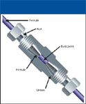
Figure 4: Zero-dead-volume union. Reproduced from reference 2 with permission from Upchurch Scientific.
Connecting Fused-Silica Capillaries
When connecting segments of fused-silica capillary, a union must be used that maintains a consistent flow path diameter to avoid misalignment, leakage, and dead volume.
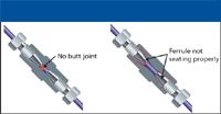
Figure 5: Misassembled zero-dead-volume union. Reproduced from reference 2 with permission from Upchurch Scientific.
A true zero-dead-volume union, when assembled properly, forms a butt connection between the two tubing segments, minimizing band-broadening and potential carryover (Figure 4). However, making a successful connection requires some effort. Otherwise, all the advantages of using a zero-dead-volume union are lost (Figure 5). Proper assembly of a zero-dead-volume connection is aided by use of a gauge plug, which helps ensure that a true butt connection is established between the two capillary segments (Figure 6).

Figure 6: Assembly of zero-dead-volume union with gauge plug. Reproduced from reference 2 with permission from Upchurch Scientific.
Webbed unions provide a convenient alternative to zero-dead-volume unions for easy connection of fused-silica tubing (Figure 7). However, the through-hole in the web adds flow path volume, which can contribute to band-broadening and carryover. When using webbed unions, it is important to use tubing sleeves for proper alignment of the tubing with the through-hole (Figure 8). To avoid adding unswept volume to the flow path, it is important to select a union with a through-hole as close to the capillary i.d. as possible.
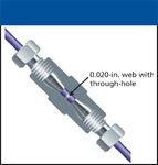
Figure 7: Webbed union. Reproduced from reference 2 with permission from Upchurch Scientific.
Proper tubing alignment is crucial for all unions. The concentricity tolerance for the through-holes should be as tight as possible; nonconcentric alignment can block significant portions of the flow path (Figure 9).
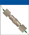
Figure 8: Webbed union assembled with sleeves. Reproduced from reference 2 with permission from Upchurch Scientific
System Validation
Confirmation of system performance is no less important in expression proteomics than in other analytical environments (3). This entails running benchmark samples to validate system performance before analysis of unknown samples, interspersing control samples between unknowns, and running blanks to eliminate carryover.
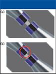
Figure 9: Importance of concentricity. Shown are (a) a properly assembled fitting and (b) a fitting assembled with poor concentricity. Reproduced from reference 2 with permission from Upchurch Scientific.
In conventional HPLC–UV, quantitative assessment of system performance is obtained from chromatographic data of standards, such as peak area and retention time precision, peak resolution, and peak symmetry. In nanoLC–MS, incorporation of a UV detector can be undesirable due to excessive extracolumn bandbroadening. In our case, sample masses are so limited that even the total ion chromatograms or base peak chromatograms do not provide sufficient chromatographic data to adequately assess system performance. Instead, we rely upon database search results (for example, search scores, protein coverage) from standard digests to provide a qualitative assessment of performance. We use a single digest, or in some cases a mixture three different digests, to validate system performance after installation of a new column, after any system maintenance procedures, and before and after each sample set.
Sample carryover is a concern in establishing correct protein identification. In our case (analysis of spots from two-dimensional [2D] gels), identical protein identification results for subsequent samples could arise from carryover (false positives) or from posttranslational modifications of the same protein (true positive; a protein with posttranslational modifications such as phosphorylation can occur as a "train" of spots across the gel). The only way to clearly distinguish between these is insertion of blanks between samples. In a core facility or service lab, where samples of unknown or unreliable quality are submitted by outside researchers, use of blanks and system controls is critical to confirming the accuracy of the result and ensuring the credibility of the laboratory.
Summary
The sensitivity demands for LC–MS systems used in expression proteomics require the use of capillary HPLC columns coupled to nanospray ionization sources. Chromatographers accustomed to using conventional millimeter-diameter columns operated at milliliter-per-minute flow rates will need to learn a new set of skills to properly configure a nanoLC system and keep it running reliably. These include selecting the appropriate capillary tubing dimensions and composition, selecting the appropriate type of compression fittings, and the use of proper assembly techniques to ensure leak-free connections without dead volume, which could compromise chromatographic performance. Once a nanoLC system is configured and brought on-line, system performance must be validated with appropriate standards before committing to analysis of unknown samples. During routine operation, system performance must be checked regularly with known standards or controls interspersed between samples.
Tim Wehr "Directions in Discovery" editor Tim Wehr is staff scientist at Bio-Rad Laboratories, Hercules, California. Direct correspondence about this column to Direct correspondence about this column to "Directions in Discovery," LCGC, Woodbridge Corporate Plaza, 485 Route 1 South, Building F, First Floor, Iselin, NJ 08830, e-mail lcgcedit@lcgcmag.com
References
(1) T. Wehr and C. McEathron, LCGC 24(3), 286–294 (2006).
(2) J.W. Batts, All About Fittings (Upchurch Scientific, Oak Harbor, Washington, 2003).
(3) K.M. Gooding, B. Hodge, and R.K. Julian, Jr., LCGC 22(4), 354–361 (2004).

Common Challenges in Nitrosamine Analysis: An LCGC International Peer Exchange
April 15th 2025A recent roundtable discussion featuring Aloka Srinivasan of Raaha, Mayank Bhanti of the United States Pharmacopeia (USP), and Amber Burch of Purisys discussed the challenges surrounding nitrosamine analysis in pharmaceuticals.
Extracting Estrogenic Hormones Using Rotating Disk and Modified Clays
April 14th 2025University of Caldas and University of Chile researchers extracted estrogenic hormones from wastewater samples using rotating disk sorption extraction. After extraction, the concentrated analytes were measured using liquid chromatography coupled with photodiode array detection (HPLC-PDA).


