Multiple Dimensions of Separations: SPME with GCxGC and GCxGC–TOF-MS
LCGC Europe
In this article, the combination of SPME with GCxGC and GCxGC–TOF-MS is discussed using mixtures of solvents as example analytes
Two-dimensional gas chromatography (GC×GC) and GC×GC–time-of-flight (TOF)-mass spectrometry (MS) have received increasing attention as powerful techniques for separation and analysis of extremely complex mixtures. Over the past 20 years, solid-phase microextraction (SPME) has become a staple sample preparation technique for a large variety of GC analyses. With a few additional considerations, SPME is combined readily with GC×GC or GC×GC–TOF-MS to provide easily automated and solvent-free sample preparation. This combination provides up to six dimensions of separation power in analytical method development that can be used to provide the required selectivity or can cause unwanted selectivity through sample losses or slow kinetics. In this article, the combination of SPME with GC×GC and GC×GC–TOF-MS is discussed using mixtures of solvents as example analytes. Optimization of the injection process is emphasized, as extractions remain generally the same as in traditional SPME–GC. To ensure good peak shapes, the injection liner, carrier gas flow rate and column temperatures must be optimized carefully. The differences in carrier gas flow optimization between GC×GC with flame ionization detection and GC×GC–TOF-MS also are discussed.
Since the development of comprehensive two-dimensional gas chromatography (GC×GC) by Phillips and coworkers in 1990, and most notably in the past five years, GC×GC and multidimensional GC by heartcutting have become increasingly popular among analysts in a variety of disciplines.1 A number of recent reviews describe advances in GC×GC that demonstrate its high selectivity and ability to separate extremely complex mixtures, so these are not repeated here.2 GC×GC is moving rapidly from the realm of being a research technique for hard-core chromatographers and into use by the broader community. GC×GC coupled with time-of-flight-mass spectrometry (GC×GC–TOF-MS) provides perhaps the ultimate in chromatographic separation and identification power, combining the separation power of multidimensional GC with the sensitive detection and identification capability of electron impact TOF-MS. A recent article demonstrating GC×GC–TOF-MS in athletic doping control illustrates the separation, detection and quantification power of GC×GC–TOF-MS.3 Further selectivity and sensitivity may be achieved by adding a concentrating and selective extraction technique, such as solid-phase microextraction (SPME), to GC×GC analysis. In this article, we discuss the principles, advantages and challenges in combining SPME with GC×GC and with GC×GC–TOF-MS. While the same extractions can be used with both traditional and multidimensional GC, there are additional injection considerations that result from the two-column combination in multidimensional separations and the additional selectivity afforded by the two column system can also require rethinking of sampling procedures and extraction chemistry.
SPME was developed about 20 years ago as a solvent-free alternative to traditional extraction methods for the analysis of volatile organic contaminants in water.4,5 Headspace SPME subsequently became the method of choice for volatile compounds such as solvents.6 Because of its ease of use and automation, SPME has become one of the most popular sample preparation methods for GC. Being a solvent-free extraction and injection technique, SPME has unique properties and capabilities as an injection method.7 Most notably, there is no interference in the chromatogram from the presence of the large solvent peak found in traditional liquid injection chromatograms. There is also none of the beneficial band focusing due to solvent effects, as there is no traditional solvent. The only band-focusing mechanism available is cold trapping at the head of the analytical column. A complete discussion of the beneficial solvent effects, and how to avoid deleterious effects involved in traditional liquid injections, is provided in the comprehensive text on injection by K. Grob,8 which is a must-read for any chromatographer seeking to optimize or troubleshoot GC injections. Lacking solvent effects, SPME–GC injections must be optimized carefully, depending upon analyte volatility and instrumental conditions with an eye toward minimizing width of the injected band.
Effective injection using SPME requires careful consideration of the desorption conditions within the inlet. Generally, desorption should be carried out as rapidly as possible, followed by thermal refocusing of the desorbed analytes at the head of the analytical column. The most important variables are: the diameter of the glass sleeve, purge time, flow rate of the carrier gas, inlet temperature, initial column temperature, stationary phase and film thickness of the capillary column.
For lower vapour pressure analytes such as drugs or hydrocarbons larger than about C10, SPME injection conditions are usually very straightforward. Very often, a traditional straight-bore splitless glass sleeve of about 2 mm inside diameter, with no packing or glass wool, will suffice. Purge time and flow rate must be set sufficiently to fully desorb the analytes and transfer them during the splitless period to the column. This can be studied simply by varying purge time and flow rate (one at a time) and by maximizing the detector response versus the purge time or flow rate. Inlet temperature is set sufficient to volatilize the analytes but not higher than the maximum temperature for the fibre coating being used. Initial column temperature should be set low enough to focus the analytes at the column head. For less-volatile compounds, this is quite straightforward, as demonstrated in our previous work.9 The fibre is often left in the inlet for a time following the splitless period, with the purge flowing, to remove any remaining analyte or interferences and avoid carryover to the next sample.
Figure 1, which was published originally about 12 years ago,9 demonstrates several aspects of traditional SPME–GC injections. It shows separation of several alkanes using a temperature-programmed separation on a nonpolar column following SPME. The SPME injection was performed using a large 4 mm inside diameter glass sleeve in the inlet. Generally, this wide diameter sleeve would never be used for SPME or splitless injections. This one remained in the GC system by accident during an SPME training exercise. The early eluted compounds show significant band broadening as they are transferred from the fibre to the inlet during an entire 60 s splitless period. The initial temperature of the temperature programme is not sufficiently low and the stationary phase film is not sufficiently thick to effectively retain and focus these analytes. As the molecules get larger, the peaks become sharper, finally becoming equivalently sharp as the same compound injected using a traditional fast liquid injection. These lower vapour pressure compounds are very effectively focused. This illustrates the need for much more careful SPME injection optimization for more volatile analytes, yet little optimization for less volatile analytes, assuming that they can be desorbed in the first place.
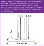
Figure 1
With no solvent effects or thermal focusing, volatile compounds are much more difficult to focus at the column head, so rapid desorption and transfer to the column is a must. First, a small diameter, 0.75 mm, glass sleeve designed for SPME should be used. This will facilitate rapid desorption, but beware that the small diameter of the glass sleeve can limit the volumetric flow rate in the inlet, causing potential difficulty in using wider (0.32 mm or more) columns or high split ratio following desorption and possibly causing flow-related errors with some electronic flow controllers. The initial column temperature should be set as low as possible. In our laboratory, we attempt to optimize methods for initial column temperatures of 35 °C or higher to avoid the inconvenience of using a cryogenic oven while maintaining reasonable turnaround time between temperature programmes. A thicker stationary phase film or careful matching of the stationary phase and analyte polarities (to enhance analyte retention) will allow higher initial column temperature. However, for analysis of highly volatile compounds, a cryogenic oven and a thick stationary phase film might be needed.
The ease of extraction and automation in SPME and the high resolving power of GC×GC and GC×GC–TOF-MS make these a natural combination. The first report of SPME–GC×GC in the literature by Perrera and colleagues10 occurred in 2002 for the analysis of volatile emissions from wounded plants. Recent applications have involved the analysis of pesticide residues in tea, identification and fingerprinting in cachaca (a distilled beverage) production, honey volatiles and bumblebee gland secretions.11–14 In each of these applications, headspace SPME was used under varying conditions. In the bumblebee example, for instance, a 100 mm polydimethylsiloxane (PDMS) fibre was exposed in the presence of a flying male bumblebee inside a glass container. In this article, as in many on SPME–GC, the extraction and GC conditions are described quite thoroughly, while the SPME injection conditions are missing necessary details such as inlet liner dimensions, inlet pressure during desorption and desorption temperature, often making the work difficult to reproduce without significant additional optimization.
The experimental work described in this article illustrates the special considerations involved in the use of SPME with GC×GC and GC×GC–TOF-MS using the analysis of common solvents as examples. Solvents were chosen because, although these mixtures can be separated by traditional single dimension GC, they are familiar to nearly all gas chromatographers, providing a common point of reference. The full resolving power of GC×GC is demonstrated in the references cited herein.
Experimental
All chemicals and reagents were purchased from Sigma-Aldrich (St Louis, Missouri, USA), were of the highest purity available, and were used without further purification. Water was 18.2 MΩ Milli-Q (Millipore, Milford, Massachusetts, USA) obtained in our laboratory. SPME fibres were obtained from Sigma Aldrich Supelco (Bellefonte, Pennsylvania, USA) and were conditioned according to the manufacturer's instructions.
The GC×GC–flame ionization detection (FID) system was obtained from LECO (St Joseph, Michigan, USA) and consisted of a model 6890 gas chromatograph (Agilent Technologies, Wilmington, Delaware, USA) modified by the addition of the secondary oven, thermal liquid nitrogen modulator and the associated pneumatics. Instrument control and data acquisition were performed using ChromaTOF software (LECO). For GC×GC–TOF-MS, a Pegasus 4D time-of-flight mass spectrometer and the associated control software (LECO) were added to the original GC×GC system. The first dimension column was a 60 m × 0.32 mm, 1.8 μm df DB-624 (J&W/Agilent, Wilmington, Delaware, USA) and the second dimension column was 1.5 m × 0.25 mm, 0.25 μm df Rtx-WAX (Restek, Bellefonte, Pennsylvania, USA).
For GC×GC–FID work, the first dimension column was 30 m × 0.25 mm, 1 μm df Rtx-5 (Restek). The second dimension column was 1.1 m × 0.25 mm, 0.5 μm df Rtx-WAX (Restek). The first dimension column was temperature programmed with a 35 °C hold for 10 min and ramped at 10 °C/min to 220 °C.
The carrier gas was helium (AGL, Wayne, New Jersey, USA), the inlet temperature 250 °C and the transfer line temperature 240 °C. The mass spectrometer settings were 70 eV electron impact at 200 spectra/s with mass range 30–300 Da. Glass inlet sleeves were obtained from Restek.
Modulation was performed using a two-stage modulator with cryogenically cooled liquid nitrogen for the cold jets and heated nitrogen gas for the hot jets. The modulator was operated to provide a 2 s modulation period and programmed to maintain the same temperature as the secondary oven. The modulator gave a 0.4 s hot pulse and a 1.6 s cooling time between stages. For the FID work, the modulation period was 4 s.
Solvent mixtures were prepared at approximately 1.00 ppm each in water by first preparing 100 ppm each in methanol and diluting 1:10 with water. Mixtures included Class 1, 2 and 3 solvents for pharmaceutical residual solvent analysis as described in the United States Phamacopeia (USP) General Chapter <467> Residual Solvents15 or as described in the text accompanying each figure.
Results and Discussion
The combination of SPME with GC×GC and GC×GC–TOF-MS provides numerous possibilities for obtaining selectivity in complex separation problems. If the steps in a chromatographic method are each considered as an opportunity to separate analytes of interest from the matrix and interferences, up to six dimensions of separation — sampling, extraction, injection, first dimension separation, second dimension separation and detection — may be obtained. In each dimension, both the kinetics (rate) and thermodynamics (partitioning) of the process should be considered, along with that step's effects on the later steps in the process. For example, the enhanced separation power of GC×GC and TOF-MS might allow earlier steps such as sampling, extraction and injection to be simplified. However, poor sampling, extraction, or injection can have magnified negative effects on later GC×GC separation and detection. If sampling or extraction are ineffective or not properly performed, even the most sophisticated chromatographic and detection systems might not produce required results. The following discussion illustrates this idea for the case of SPME injection of common solvents. The literature references provide further examples of the resolving power of GC×GC.
Figure 2 is a portion of a GC×GC–TOF-MS total ion chromatogram of a 100 ppm solvent standard, injected by traditional split injection with a split ratio of 50:1. The main plot, typical of GC×GC data, is shown as a contour plot (looking down from above onto the chromatogram surface) with the brighter red colour showing larger peaks. This is a very rapid injection process that should produce narrow peaks in the first dimension and does, in this case, with many of the peaks fully contained in a single 2 s modulation period. In the second dimension, the peaks are very sharp, ranging from about 80–150 ms in width at baseline. For SPME injections to be considered effective and to not sacrifice the resolution advantages in GC×GC, peak width and shape performance should be similar to this traditional fast injection. The benefits of both GC×GC and GC×GC–TOF-MS are seen in this plot. The two dimensional system provides complete separation of all analytes; note the separation of peak 1 from the interfering peak and the separation of peaks 12, 13 and 14, which would have been coeluted in a traditional one-dimensional separation. The addition of a TOF-MS detector allows rapid identification of each peak: at 200 spectra/s, each 2 s modulation period includes about 400 mass spectra.
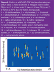
Figure 2
A small portion of an unoptimized SPME–GC×GC–FID chromatogram of common solvents is shown in Figure 3, showing a three-dimensional plot of one area of a larger chromatogram. The extraction was by headspace of a 100 ppm standard of several solvents using a carboxen-PDMS fibre, which is selective to small polar molecules. This chromatogram illustrates the two challenges in developing methods for volatile compounds by SPME–GC×GC: tailing or poor peak shape in both dimensions. Note the L-shaped appearance of the peaks. Tailing or additional peak broadening in the first dimension is caused by the slow injection process common in SPME injections. In the second dimension, tailing can be caused by slow modulation of the eluted first dimension peak into the second column or by multiple analyte interactions with the second dimension column, common in many separations on polar columns. Therefore, successful SPME injections in GC×GC require careful optimization of both the first and second dimension column flows and geometry. This separation is roughly based upon vapour pressure in the first dimension and on polarity or hydrogen bonding character in the second. Flow optimization in GC×GC–FID can be compromised by the necessity of high column head pressure, leading to peak broadening in both dimensions as illustrated in the classical van Deemter equation.16
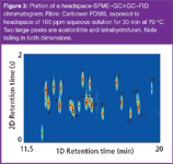
Figure 3
A portion of an unoptimized SPME–GC×GC–TOF-MS chromatogram of a solvent mixture is shown in Figure 4. The extraction was performed by direct immersion of a 100 mm polydimethylsiloxane (PDMS) fibre into 20 mL of 100 ppm solution of ICH class 1, 2 and 3 solvents in water. This is a nonpolar fibre that is by far the most popular fibre coating in use today. It is considered by many to be nonselective, but this example shows that it is, in fact quite selective. When compared to the simple liquid injection in Figure 2, several of the polar compounds are either missing or at much lower recovery, including ethyl acetate, 2-butanol, 2-methyl-1-propanol and 1,4-dioxane. Some possible unwanted selectivity from the sampling procedure may also have affected this analysis — two less-polar compounds are also missing: 2,2-dimethyl propane and 1,2-dimethoxy ethane, possibly due to evaporation from the polar aqueous solution while awaiting analysis.
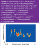
Figure 4
Interestingly, SPME clearly provides an additional channel of selectivity that can either complement the selectivity offered by multidimensional GC or can degrade it. This injection was performed using a 2 mm inside diameter glass sleeve, generally used for splitless liquid injections and SPME injections of less volatile analytes. Clearly, the peaks are broadened significantly and are tailing in both dimensions. The significant first-dimension broadening is due to the slow transfer of analyte from the fibre through the inlet sleeve and onto the column, with no corresponding focusing mechanism. Note that the later peaks are less broadened, as expected: these compounds are somewhat focused by the low initial column temperature. Additional broadening also is seen in the second dimension, most likely a result of both the extreme first-dimension band broadening and ineffective focusing of the modulated peaks in the second column. Also, with the high vacuum provided by the TOF-MS as detector, the second-dimension retention time was shortened to 2 s from 4 s, as seen Figure 3 and in our previous work, with no loss of resolution.17
The total ion chromatogram shown in Figure 5 was optimized by using a 0.75 mm inside diameter inlet liner in place of the 2 mm liner and by increasing the column flow rate during injection to minimize the extracolumn volume in the inlet and the related peak broadening. SPME desorption occurs with the inlet in splitless mode. Although desorption from the fibre coating is quite rapid in a heated inlet, the desorbed analytes must still traverse the glass sleeve, which is often slow.18 This also demonstrated unwanted selectivity caused by a problem with the sampling procedure, as the vial containing the analytes was allowed to sit in the autosampler tray over a weekend. This clearly allowed time for several of the hydrocarbons to evaporate from the aqueous solution, reducing or eliminating them entirely from the analysis. Unfortunately, highly selective and sensitive detection might not make these compounds reappear, and even if it did, reproducible quanification would be problematic. For volatile analytes, the narrow diameter glass sleeve combined with a higher flow rate generated peaks almost as narrow as those seen in the liquid injection. Earlier eluted peaks have similar widths and shapes to the later peaks. The solvent peaks, all of which are again present, now show acceptable peak shape and little band broadening versus a traditional liquid injection.
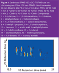
Figure 5
Two-Dimensional Column Flows
One challenge in both traditional liquid and SPME injections with GC×GC is that a second injection onto the second-dimension column is performed during the modulation process. On our system, this is accomplished by a two stage modulator using cold and hot jets of nitrogen to alternatively freeze narrow analyte bands at the head of the second column and then to rapidly desorb them into the column. To accomplish this, the timing sequence of the cold and hot jets must be carefully optimized. Several authors have reviewed these method development steps.19,20 Additionally, in GC×GC–TOF-MS, the carrier gas velocity in the second-dimension column, which is usually very short (1–3 m), is quite high, often reaching 200 cm/s or higher. The second-dimension separation, therefore, is a very fast separation on a short column. Seemingly minor problems with injection bandwidth will be significantly magnified in this situation.
As seen in Figures 3–5, in GC×GC–TOF-MS, the hold-up time (tm) in the second dimension is quite short, in this data, about 0.4 s. For the 1.5 m × 0.25 mm column employed, this implies an average linear gas velocity of about 350 cm/s and a volumetric carrier gas flow rate of about 11 mL/min under a near vacuum as the outlet of the 1.5 m column is at about 10–7 Torr. This flow is very far to the right, in the mass transfer region of a typical van Deemter plot, and furthermore, it is so high that the second dimension temperature should be optimized carefully to maximize retention. In our work, the second-dimension temperature was lowered as much as practical with this instrumentation: to 5 °C above the first dimension. This leads potentially to the band broadening and tailing seen in the second dimension chromatograms. The maximum retention factor (k) seen in this data is about 3, with many of them less than 1. Also, for the 1.5 m second-dimension column, there are only about 3000–4000 theoretical plates. If resolution is considered a function of retention factor, selectivity and theoretical plates and retention factor and theoretical plates are low, then selectivity must be kept high to achieve resolution. This implies careful study and optimization of the stationary phase choice and lowering the second-dimension temperature to enhance retention.
Conclusions
SPME combined with GC×GC or GC×GC–TOF-MS provides a straightforward, yet powerful separation system. However, as the separation power increases so does the need for careful optimization and understanding of each step. For SPME, both the extraction and injection conditions are important in obtaining effective separations. The critical injection parameters are glass sleeve diameter, inlet flow rate, and band focusing at the column head. If focusing is strong (low column temperature, thick film, high retention) then inlet liner conditions are not as critical, however if focusing is weak (higher column temperature, thin film, low retention), then inlet liner conditions should be optimized carefully to provide the fastest sample transfer possible using a narrow glass sleeve and high flow rate. In this work, it is clearly seen that even the highly sophisticated columns and detection afforded in GC×GC–TOF-MS are not capable of mitigating a poor job optimizing the previous sampling and injection. However, the separating power of SPME–GC×GC–TOF-MS is perhaps unrivaled, offering up to six dimensions of separation for complex samples.
Acknowledgments
The authors gratefully acknowledge the contribution of technical and instrumentation support from LECO Corporation, columns from Restek, and SPME fibres from Supelco. J.S. and M.D. acknowledge financial support from the Clare Booth Luce Foundation. N.S. acknowledges financial support from Sanofi-Aventis for the Centre for Academic Industry Partnership.
Nicholas H. Snow, Jerianne Sinex and Mandelle Danser, Seton Hall University, South Orange, New Jersey, USA.
References
1. Z. Liu and J. Phillips, J. Chromatogr. Sci., 29(6), 227–231 (1991).
2. M. Adahchour et al., TrAC Trends Anal. Chem., 25, 438–454, 540–553, 726–741, 821–840 (2006).
3. A.I. Silva Jr. et al., J. Chromatogr. A., 1216, 2913–2922 (2009).
4. C.L. Arthur and J. Pawliszyn, Anal. Chem., 62, 2145–2151 (1990).
5. J. Pawliszyn, Solid Phase Micro Extraction Theory and Practice (John Wiley and Sons, New York, 1997).
6. Z. Zhang and J. Pawliszyn, Anal. Chem., 65, 1843–1848 (1993).
7. J.J. Langenfeld, S.B. Hawthorne and D.J. Miller, J. Chromatogr. A, 740, 139–145 (1996).
8. K. Grob, Split and Splitless Injection in Capillary Gas Chromatography (John Wiley and Sons, New York, 2001).
9. P.D. Okeyo and N.H. Snow, LCGC N. Am., 15, 1130–1136 (1997).
10. P.M.M. Perrera, P.J. Marriott and I.E. Galbally, Analyst, 127, 1601–1607 (2002).
11. J. Schurek et al., Analytica Chimica Acta, 611, 163–172 (2008).
12. Z.L. Cardea et al., Talanta, 74, 793–799 (2008).
13. T. Cajka et al., J. Chromatogr. A, 1216, 1458–1462 (2009).
14. B. Kalinova et al., J. Nat. Products, 72, 8–13 (2009).
15. United States Pharmacopeia National Formulary 2009, General Chapter <467> Residual Solvents.
16. R.L. Grob, Modern Practice of Gas Chromatography, R.L. Grob and E.F. Barry, Eds. (John Wiley and Sons, New York, 2004), pp. 25–64.
17. C.M. Crimi and N.H. Snow, LCGC N. Am., 26(1), 62 (2008).
18. N.H. Snow and P. Okeyo, J. High Resolut. Chromatogr., 20, 77–80 (1997).
19. J. Dalluge, J. Beens and U.A.Th. Brinkman, J. Chromatogr. A, 1000, 69–108 (2003).
20. J. Dalluge et al., J. Chromatogr. A, 965, 207–217 (2002).
Study Examines Impact of Zwitterionic Liquid Structures on Volatile Carboxylic Acid Separation in GC
March 28th 2025Iowa State University researchers evaluated imidazolium-based ZILs with sulfonate and triflimide anions to understand the influence of ZILs’ chemical structures on polar analyte separation.
Quantifying Microplastics in Meconium Samples Using Pyrolysis–GC-MS
March 26th 2025Using pyrolysis-gas chromatography and mass spectrometry, scientists from Fudan University and the Putuo District Center for Disease Control and Prevention detected and quantified microplastics in newborn stool samples.


