The Hydrophobic-Subtraction Model for Reversed-Phase Liquid Chromatography: A Reprise
LCGC North America
Reversed-phase liquid chromatographic columns can be compared quantitatively for differences in selectivity by means of the hydrophobic-subtraction model. This allows selection of columns that are either equivalent or different in selectivity. The present paper both presents a summary of this approach and shows in detail how to use it in practice.
Reversed-phase liquid chromatographic columns can be compared quantitatively for differences in selectivity by means of the hydrophobic-subtraction model. This approach allows selection of columns that are either equivalent or different in selectivity. The present article presents a summary of this model and shows in detail how to use it in practice.
For the practical user of reversed-phase liquid chromatography (LC) columns, two cases are of particular importance when comparing column selectivity. We’ll refer to these as equivalent and orthogonal columns, with examples given in Figure 1 for three columns under identical operating conditions. For two columns to be equivalent, ideally they would give identical separation, but for practical use they can differ somewhat as long as they subjectively give the same separation and enable the same quantitative results to be obtained. The separations for the two columns shown in Figures 1a and 1b are almost identical, so these two columns would qualify as equivalent. The quantitative results of analysis on the two columns would be expected to be the same. We might desire equivalent columns so that we could specify an alternate column for a method or to substitute for a column that is no longer available to us. Often columns do not need to be as similar as those of Figures 1a and 1b to give the same analytical results, especially if the separations are not too challenging.
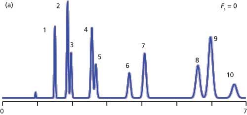
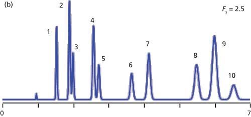
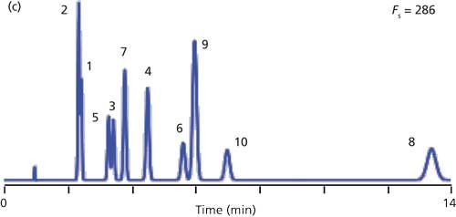
Figure 1: Simulated chromatograms for equivalent and orthogonal columns. (a) ACE C18, (b) XTerra MS C18, and (c) Zorbax Bonus RP.
Identifying an equivalent or orthogonal column is much more difficult than looking at the label on the column box. For example, a C18 and phenyl column from one manufacturer may be more similar than two C18 columns from different manufacturers. At one time, it was thought that all columns with the same bonded phase chemistry were equivalent. This is reflected in the somewhat outdated classification by the United States Pharmacopeia (USP), where different “L” classifications are used (1). For example, all C18 columns are classified as L1. Today it is well known that such classification of column chemistry is oversimplified, and that great differences in the appearance of the chromatogram are possible with different L1 columns. It is likely that there are more than 1000 reversed-phase LC columns on the market today (2), so tools are needed to help determine which of these columns are equivalent or orthogonal.Sometimes, particularly during method development, we desire an orthogonal column. An orthogonal column should give a distinctly different separation from the original column, including significantly different resolution among adjacent peaks in the original separation, as well as reversals in elution order. The separation of Figure 1c is very different from that of Figure 1a or 1b, so this column could be considered orthogonal. The peaks in Figures 1a and 1b are eluted in numeric order, whereas the order for Figure 1c is 2, 1, 5, 3, 7, 4, 6, 9, 10, and 8. Note especially that peak pairs 2–3 and 4–5 were marginally separated on the first two columns, but easily separated on the column of Figure 1c. Finding an orthogonal column does not mean that all the peaks will be completely resolved, but instead that the separation is quite different from the starting column. Additional method development efforts often will be required to get an acceptable separation (for example, to improve separation of peak pairs 2–1 and 5–3 of Figure 1c). Orthogonal columns may be desired to resolve hard-to-separate peak pairs, to help assure us that additional peaks are not “hidden” under existing peaks, or to otherwise make changes to an existing separation. Orthogonal columns are also essential for the two columns used in two-dimensional (2D) separation.
The purpose of the present article is to describe the hydrophobic-subtraction (H-S) model of reversed-phase selectivity as it applies to identifying equivalent and orthogonal columns. We briefly describe the main interactions important in reversed-phase selectivity and we show how the H-S model has been incorporated into free web-based tools (3,4) that help users choose equivalent or orthogonal columns from the myriad choices available.
Column Selectivity
When we started work on column selectivity, our goal was this: Is it possible to test reversed-phase LC columns with a simple mixture of test solutes under standardized conditions and quantitatively predict column equivalency or orthogonality for other samples under other conditions? With the chromatograms of Figure 1, we could use a visual comparisons of columns. A simple way to quantitatively compare column selectivity is shown in Figure 2. Here retention, expressed as log retention factor k, is compared between two columns. Retention factors of the 10 solutes used in Figure 1 are shown as diamonds and the best fit line is shown in red. In Figure 2a retention on the columns of Figure 1a and 1b is compared; all the points lie on or very close to the trend line, which means that the relative retention is very close to the same for each solute on each column. We would say that these two columns are equivalent. Figure 2b shows a comparison of the retention of the same solutes on the columns of Figure 1a and 1c; the scatter about the trend line is quite apparent. We can see peak reversals take place for every adjacent peak pair except peaks 9–10. There is a much greater difference between these two columns than there is between the columns of Figure 2a. The larger the scatter about the best fit line, the greater the difference in the columns. This scatter is quantitatively expressed as the standard error (SE) of the curve, and can be related to the average difference in selectivity, α, between the two columns.
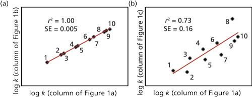
Figure 2: Comparing column selectivity by comparing retention (log k) of solutes on two columns. (a) Column of Figure 1a versus 1b (ACE C18 and XTerra MS C18); (b) column of Figure 1a versus 1c (ACE C18 and Zorbax Bonus RP). Solutes: 1. 4-nitrophenol, 2. acetophenone, 3. benzonitrile, 4. 5-phenylpentanol, 6. 4-n-butylbenzoic acid, 7. toluene, 8. cis-chalcone, 9. ethylbenzene, and 10. trans-chalcone.
To compare columns, a set of solutes needs to be chosen that adequately represents the important interactions between the solute and column. We determined the retention of 87 solutes on 10 high-purity, type-B silica C18 columns under two isocratic conditions (acetonitrile–phosphate buffer at pH 2.8 and 7.0). Based on this data set, a multiple regression technique was used to derive equation 1, which estimates retention, k, for a given solute within ±1% (1 standard deviation [SD]).

Here k is the retention factor for a particular solute, kEB is the retention factor for ethylbenzene, the Greek letters (η′, σ′, β′, α′, and κ′) are characteristics of the solutes, and the capital letters (H, S*, A, B, and C) are column parameters. The five terms describing selectivity are i, the hydrophobic interaction between the solute and the column; ii, the resistance of the bonded phase to penetration by bulky molecules; iii, hydrogen bond (H-B) interactions between basic solutes and acidic sites (silanols) in the column; iv, H-B interactions between acidic solutes and a vicinal-silanol pair on the column surface (shown as “x” in Figure 3); and v, cation exchange between ionized bases and ionized silanol groups in the column. These five interactions are illustrated in the representations of Figure 3. The retention factor for ethylbenzene kEB is used to compensate for differences in packing surface area, which have no effect on column selectivity. The column parameters (H, S*, A, B, and C) are discussed further later in this article.
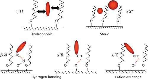
Figure 3: Conceptual illustration of the five major solute-column interactions of the hydrophobic-subtraction model.
For the characterization of column parameters (H, S*, A, B, and C), 16 suitable test solutes were chosen based on their known solute parameters (η′, σ′, β′, α′, and κ′). Experimental runs for these 16 test solutes allow the calculation of column parameters (H, S*, A, B, and C) for any column. After the column parameters are known for two columns, the quantitative difference in selectivity between the columns can be determined using the technique and web-based comparison tools (3,4) described later.
The current discussion is intended as a recapitulation of other publications on the H-S model, and describes the proposed molecular interactions. For a more detailed discussion of the H-S model, readers are encouraged to read the review (5) plus later reference (6); the cross-references contained in these two articles contain detailed discussions of all aspects of the model.
Column Variables
The column variables H, S*, A, B, and C correspond to the five most important chemical interactions between solute molecules and the stationary phase (as discussed below) and define column selectivity.
Hydrophobic Interaction, H (Term i in Equation 1)
It is not surprising that the dominant contributor to retention with reversed-phase LC columns is hydrophobic interaction between solutes and the stationary phase, because this is the mechanism of retention usually assigned to reversed-phase columns (7). In fact, H is such a dominant factor that its contribution to retention overshadows the minor-but from a selectivity standpoint more important-factors S*, A, B, and C. (This dominance of hydrophobic retention accounts for the relatively strong correlation, r2 = 0.73, in Figure 2b even when the selectivity is quite different.) Because of its dominant influence, the value of H must be mathematically removed during the calculation of H, S*, A, B, and C, accounting for the name hydrophobic-subtraction model of reversed-phase retention.
Hydrophobicity accounts for the general interaction of hydrophobic solute molecules with the hydrophobic stationary phase. The more hydrophobic the solute, the larger its value of η. Hydrophobic interaction is illustrated in the cartoon of Figure 3. H defines the hydrophobic nature of the column.
Steric Interaction, S* (Term ii)
The density and ligand length of the bonded phase on the silica surface of reversed-phase LC columns will vary from one column to another. As a result, a bulky molecule will have more difficulty penetrating into the bonded phase of a densely bonded phase than a less densely bonded one. Or for the same bonded phase, a more bulky molecule will have a harder time penetrating the bonded phase than a less bulky one. From an oversimplified viewpoint (see reference 8 for more details), this interaction is somewhat analogous to size-exclusion chromatography (SEC) in that both SEC and S* depend on the hydrodynamic diameter of the solute molecule and relate to the ease of that molecule entering a cavity in the column. However, SEC describes solute access to the column pores, whereas S* describes the resistance to penetrating the bonded phase.
Steric selectivity is illustrated in Figure 3 for two molecules of different hydrodynamic radius. The less bulky molecule can more easily penetrate the bonded phase than the more bulky one. With steric selectivity, σ′ is related to the hydrodynamic radius of the solute molecule and S* is related to the bonded phase density and other bonded phase characteristics that result in poorer penetration by bulky molecules than less bulky ones.
Column Hydrogen-Bond Acidity, A (Term iii)
The interaction of neutral proton acceptors (nonionized bases) with acidic silanol sites on the column is responsible for the column A value. As expected, solute molecules that are better proton acceptors (greater hydrogen-bond basicity) are more strongly retained. Conversely, factors that reduce the availability of silanol groups will tend to reduce the value of A. Thus, endcapping and more dense bonding of the stationary phase will result in smaller A values. Column hydrogen-bond acidity is illustrated in Figure 3 by the interaction of a nonionized basic substituent, B, with an acidic silanol group, Si-OH.
Column Hydrogen-Bond “Basicity,” B (Term iv)
A silica surface usually is thought to be acidic in nature, yet our studies observed that there is a significant interaction of proton donors, such as nonionized acids or phenols, with the stationary phase. We use the term “basicity” to refer to the hydrogen-bond acceptor strength of such interactions. Whereas the other column variables (H, S*, A, and C) are fairly easy to describe in terms of the simple interactions shown in Figure 3, B is somewhat less obvious. One of the key sources of column basicity is interaction with vicinal silanol groups (X) on the silica surface. Vicinal silanols comprise two adjacent silanol groups that are internally hydrogen bonded. This enables them to doubly hydrogen-bond with carboxylic acids to form a stable ring structure as seen in Figure 4a. Phenolic solutes are less strongly retained by vicinal silanols, which can be explained by the single hydrogen-bond interaction of Figure 4b. The α′B interaction of Figure 4 is observed for all silica columns. Low purity, type-A silica columns have an additional α′B interaction, attributed to the presence of metal impurities, particularly Al(III) and Fe(III). Embedded-polar-group (EPG) columns show a third type of α′B, which involves the selective retention of both acids and phenols by proton donor sites (amide, carbamate, or urea) present in such columns. These additional interactions are the reason for generalizing the column interaction site in Figure 3 as “X.” The α′B interactions are described further in reference 6.
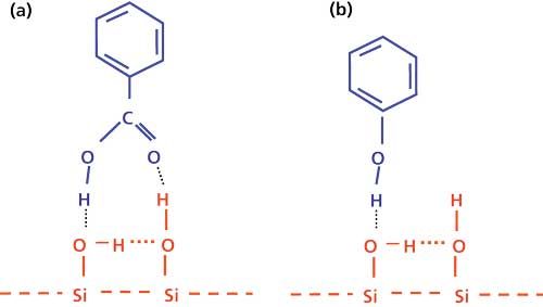
Figure 4: Illustration of column “basicity.” Interaction of (a) carboxylic acids and (b) phenols with vicinal silanols.
Column Cation-Exchange Interaction, C (Term v)
The final term from equation 1 is the cation-exchange term, C. As with hydrophobicity, H, cation exchange on silica is a well-known phenomenon in reversed-phase LC. Processes that increase the ionization of silanol groups, such as increased metal contamination of type-A columns and increased mobile phase pH, result in increased values of C. This is characterized by increased retention of ionized basic solutes. Values of C are the result of solute interactions with free column silanols; see reference 9 for further details. A graphic representation of the cation-exchange interaction is shown in Figure 3.
Aromatic and Dipole Interactions
Equation 1 lists the five primary interactions H, S*, A, B, and C that allow prediction of retention factors within ±1% (1 SD) for type-B alkylsilica columns. An obvious question arises: Are there other unaccounted for interactions? Indeed, there are (10). Equation 1 might be expanded to take into account π-π interactions between aromatic solutes and alkyl phenyl or cyanopropyl columns (11) as well as dipolar interactions with cyanopropyl columns (12). Consequently, equation 1 is somewhat less reliable for these two column types. Ignoring these additional interactions will not often affect the usefulness of the values of H, S*, A, B, and C for identifying equivalent or orthogonal columns.
Comparison of Column Selectivity by Means of the Parameter Fs
After values of H, S*, A, B, and C are determined for a column, based on experimental testing, these column parameters can be used to help identify columns that are either equivalent or orthogonal to each other. There are two ways to compare columns in this context: graphical and mathematical. We’ll look at these next, then we’ll examine a web-based tool that can be used for practical column comparison.
Comparison of Column Selectivity Using Fs
Figure 5 provides a graphical illustration of the concept of column comparison for just three column properties (S*, A, and B). The difference in selectivity can be measured by the distance in three-dimensional (3D) space between points for the two columns (red dashed line).
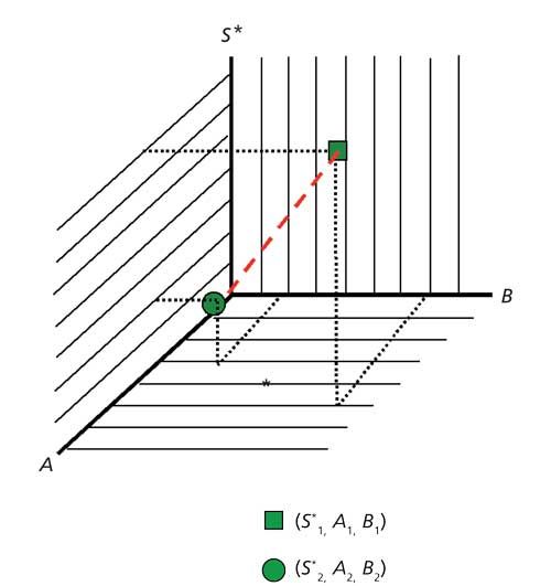
Figure 5: Graphical comparison of two columns based on column steric (S*), acidic (A), and basic (B) parameters.
This distance for three variables can be obtained from the Pythagorean theorem:

where Fs is the difference in selectivity, comparable to the distance between the two points in Figure 5. This technique of comparison can be mathematically (but not visually) extended to all five column parameters:

Now we can compare any two columns for which we have measured the column parameters H, S*, A, B, and C. If Fs is small, the columns are similar; if Fs is large, the columns are different. For the best results, a set of loading coefficients (not shown, see reference 13) are added to equation 3 to take into account the different influence of H, S*, A, B, and C on selectivity and the final value of Fs. As noted above, H contributes only a little to selectivity, although it is the main factor in determining retention, k.
For practical use, values of Fs can be generalized as follows:
- Fs ≤ 3: columns are equivalent for most separations
- 3 < Fs < ~10: columns are likely to be equivalent, especially for samples that contain only a few solutes with resolution, Rs >> 2
- Fs ≥ 100: columns are orthogonal when ionized solutes are present in the sample
- Fs ≥ 35: columns are orthogonal when the sample comprises predominantly nonionized analytes and when values of C in equation 3 are suppressed (see Fs(-C), later in this article)
These are generalizations to be used as guidelines. In a collaborative study between several laboratories, the guidelines above were found to be reasonable for identification of equivalent (14) and orthogonal (15) columns when applied to a variety of pharmaceutical samples under different chromatographic conditions.
Web-Based Tools to Help Compare Columns
Values of H, S*, A, B, and C have been measured for ~700 commercially available reversed-phase columns. These have been tabulated into two databases that are available on the internet (3,4). Here we use the USP database (3) for illustrative purposes. First, we look at how to use the database to identify equivalent columns and then how to find orthogonal ones.
Equivalent Columns
The USP database for column comparison looks similar to Figure 6 (the figure has been simplified somewhat for clarity in the current presentation). Note that on the USP website, there are two different databases available. The “USP Database” is limited to a smaller number of C18 columns and has not been validated to the extent of the following “PQRI Database”-we recommend the latter database for use in reversed-phase column comparison. The database features are discussed briefly below and an example is presented.
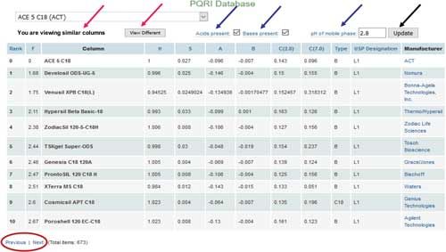
Figure 6: PQRI database comparing column selectivity (3). See text for description.
Column Selection
The drop-down box at the top of Figure 6 gives access to all the columns in the database. In the present example, we have selected an ACE 5 C18 column from Advanced Chromatography Technologies Ltd. (ACT) from the ~700 columns listed for comparison with other columns.
Similar-Different Toggle
The statement, “You are viewing similar columns,” indicates you are in the equivalent-column mode. If you would rather be in the orthogonal mode, click the “View Different” button to select that option (see red arrows).
Select Conditions
At the top of the data table, you have the option to indicate if your sample contains acids or bases, and the pH of the mobile phase (see blue arrows). These entries adjust the loading factors noted for equation 3 so that the Fs values calculated best reflect results that will be relevant to your sample. If you do not know the compounds present in the sample, check both acids and bases. When you have made the appropriate entries, click the “Update” button (upper right in Figure 6, see black arrow) and the results will be updated to reflect comparisons with your column and conditions.
Data Table
Once the Update button is pressed, the table below will display your selected column as the first entry and the 10 most similar columns in order below it. The data columns are described below.
- Rank: This is the numeric order of column similarity, beginning at 0 (the selected column) and continuing with 1 for the most similar column, and so forth.
- F: This is the website term for the Fs value. Values of Fs will increase down the table, corresponding to less similar columns.
- Column: The column name.
- H, S, A, B, C (2.8), C (7.0): These are the H, S*, A, B, and C values measured for the column. Note that values of C at pH 2.8 and pH 7.0 are shown. The calculation algorithm interpolates between these two values depending on the pH value selected when the conditions are entered (pH 2.8 in the current example).
- Type: This indicates the classification of the column type, mostly based on the column manufacturer’s information. “A”: older, lower purity, type-A silica; “B”: modern, high purity, type-B silica; “EP”: embedded polar or AQ phase; “phenyl”: phenyl phase; “CN”: cyano phase; “F”: fluoro phase; “other”: phases that don’t fit the preceding classifications, such as zirconia. As a general rule, when initially selecting a column for a separation, it is strongly recommended to choose a type-B column over a type-A column for improved reproducibility and reduced peak tailing.
- USP Description: This is the USP’s classification of the column. L1: C18; L7: C8; see reference 1 for a complete listing of the USP “L” classifications.
- Manufacturer: This is a hyperlink to the column manufacturer’s website, where more information about the column can be found.
- Previous/Next (circled at bottom left): Click on the desired word, and the columns displayed below the reference column will be updated with the previous or next 10 columns in the database. For example, if you are viewing columns 1–10, clicking on “Next” will update the display to show column 0 (your selected reference column) and columns 11–20.
Equivalent Column Example
In the example of Figure 6, the ACE 5 C18 column was chosen and 10 of the most equivalent columns are shown in the figure. The first 10 columns cover the range 1.68 ≤ Fs ≤ 2.67, so any of these would meet our general criteria for equivalent columns (Fs ≤ 3). Separation data for column 0 (ACE 5 C18), column 1 (Develosil ODS-UG-5, Nomura Chemical Co., Ltd.), and column 3 (Hypersil Beta Basic-18, Thermo Scientific) are shown in the simulated chromatograms of Figure 7. Most workers would agree that these separations are equivalent, even though the analysis times differ. (For this isocratic separation, the run times and peak retention times can be adjusted by changing the flow rate, which will have no effect on selectivity.) The column comparison study of reference 14 and the authors’ feedback from users indicate that the database does a very good job at identifying equivalent columns. Whenever an equivalent column is identified, it should be confirmed by an experimental run where the same sample and conditions are used. A further precaution to ensure column similarity is appropriate for phenyl or cyano columns. In these cases, it is best to select columns of the same type, for example, phenyl-phenyl or cyano–cyano, in each case with small values of Fs.
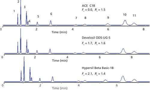
Figure 7: Comparison of equivalent columns selected from choices in Figure 6.
Orthogonal Columns
The USP database can also be used to help identify orthogonal columns. The various controls are identical to those used for equivalent columns as described above. To access the orthogonal mode, click the “View Different” button (Figure 6) and the statement “You are viewing different columns” will appear (see red arrows). The data presentation is identical to Figure 6, except that the most different column is shown just below the reference column, then the next most different, and so forth. In this section we look at two examples for the identification of orthogonal columns to point out different goals for orthogonal separation. The first example is to find an alternate column to check the effectiveness of an existing method; that is, the ability to recognize “hidden” peaks from unexpected compounds in the sample. The second example illustrates the special case when the sample comprises only nonionized solutes.
Finding an Orthogonal Column to Check an Existing Method
This example comes from an interlaboratory study (15) on the suitability of the H-S model for identification of orthogonal columns. To maximize changes in selectivity and improve the likelihood of separating “unknown” sample components, it is recommended that an orthogonal column be combined with a change of solvent; for example, methanol replacing acetonitrile, or vice versa. It is also suggested to further “tweak” selectivity by adjusting the %-organic, gradient, or column temperature to achieve separation of the original sample components.
The starting column was an Aquasil C18 column (Thermo Scientific). Under the selected conditions, 10 columns with 164 < Fs < 305 are identified. The BetaMax Acid column (Thermo Scientific; Fs = 199) was selected from columns available in the laboratory. Under the original conditions, the chromatogram shown in Figure 8a was typical. The method was a validated batch release method for the compound eluted as peak 3. Peaks 1, 2, 4, and 5 were potential impurities that required monitoring; the peak labeled with an asterisk (*) was an artifact of the gradient and not of concern. The separation on the BetaMax column with changed solvent type, gradient program, and temperature is shown in Figure 8b. The desired change in selectivity from Figure 8a is apparent in that significant changes in peak spacing have occurred. A surprise was the discovery of peak 6, which after further investigation was found to be hiding under peak 3 in the original separation. But this is the result an orthogonal separation is intended to achieve-to help ensure that hidden peaks are exposed.
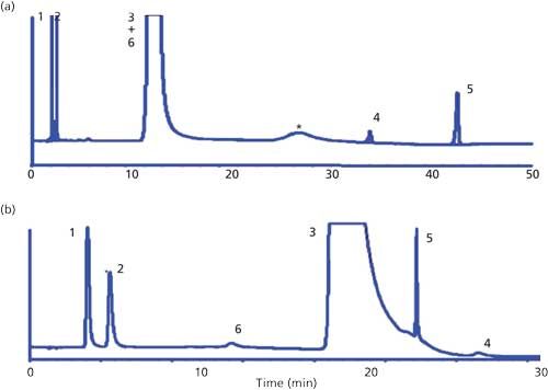
Figure 8: Achievement of an orthogonal separation by changing both the column and the mobile phase. (a) Original conditions on Aquasil C18 column: 0%–0%–100% B at 0–24.5–44.5 min; B is 10% acetonitrile; 30 °C; (b) orthogonal conditions on Betamax Acid column: 0%–0%–16%–70% B at 0–10–23–25 min; B is 50% methanol; 23 °C.
Selecting Orthogonal Columns for Nonionized Solutes
It was noted earlier that when the sample comprises primarily nonionized solutes, only Fs ≥ 35 is needed, but when this option is chosen, parameter C must be removed from the calculation. The following example illustrates this requirement (see reference 16 for more information).
In Figure 9, the separation of a sample of cations and other solutes is shown for two columns differing by Fs = 60. Although we suggested Fs ≥ 100 to ensure orthogonal columns, we would still expect significant differences in the separation for Fs = 60. This expectation is borne out when comparing the peak groupings shown in the insets for early peaks 1–4. For the YMC column (YMC America, Inc.), the elution order is 1-A-2-B-C-3=4, whereas the Capcell column (Shiseido HPLC) yields A-3=4-B=5-6-C, which might lead us to conclude that the two columns were indeed orthogonal. However, a comparison of peaks 5–14 shows no change in selectivity between columns. Note that the darkened peaks A, B, and C in Figure 9 each correspond to an ionized base. The plot of Figure 10 compares sample retention (log k) on the two columns and helps identify the problem source. Two separate trend lines are shown-one for the ionized bases A, B, and C, and the other for the remaining (nonionized) solutes. That is, there is little or no difference between the two columns for the cations alone or the other solutes alone, even though Fs = 60. In the chromatograms of Figure 9, the same observation is made when comparing the peak spacing of just the ionized bases (A, B, C) or the other compounds (numbered peaks). In either case, the Fs-value is expected to be small (not shown), but when the two groups of compounds are combined, Fs = 60. A misleading conclusion is drawn because the three ionized bases dominate the Fs calculation. We can easily deactivate the C-term of equation 1 by setting the loading coefficient to 0, which is done by leaving the “bases present” checkbox unchecked. When the C-term is eliminated in this fashion, we refer to the result as Fs(-C). For the present example, Fs(-C) = 6, so it is not surprising that the overall separation is quite similar for the two columns of Figure 9. When the sample comprises primarily nonionized solutes, it is best to use columns that satisfy the combination of Fs(-C) ≥ 35 (for nonionized solutes) and Fs > 100 (for cations) to identify orthogonal column candidates (see reference 16 for further discussion). Remember that whenever choosing equivalent or orthogonal columns, the validity of the choice needs to be confirmed by comparing experimental separation of the same sample under the same conditions on both columns.
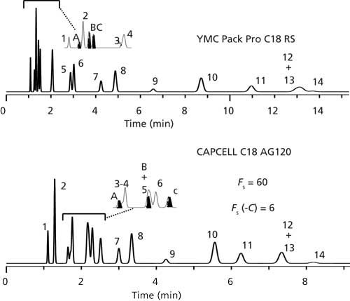
Figure 9: Comparison of retention of a sample of nonionized solutes and three cations on two columns. See text for discussion.
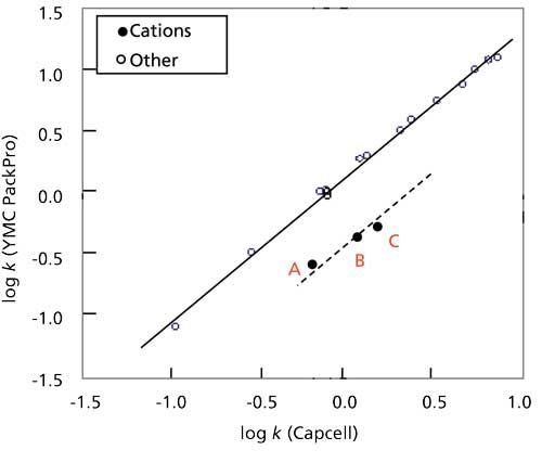
Figure 10: Comparison of solute retention from Figure 9 as a plot of log k versus log k on two columns.
Conclusions
We have presented a summary of the hydrophobic-subtraction model of reversed-phase LC column selectivity. This identifies the five predominant factors controlling selectivity: hydrophobicity, resistance to penetration of the bonded phase by bulky molecules, hydrogen-bonding interactions between nonionized acids or bases with the column, and cation exchange. Experimental k-values for a 16-component test mixture allows the characterization of a reversed-phase column (H, S*, A, B, and C). Data from ~700 reversed-phase columns have been collected and compiled in databases available on the internet. Chromatographers can use these free tools to identify columns that are equivalent to each other or very different. Although the databases have been widely successful at identifying equivalent and orthogonal columns, the predicted column matches should always be confirmed with experimental chromatograms of the target sample. More details about the H-S model and its applications can be found in the references below.
Three other procedures for the measurement of column selectivity have been reported, as reviewed in reference 5. In that review of column selectivity, a detailed comparison is made of the features of these four procedures (including the hydrophobic-subtraction model). The advantages of the latter model include:
- The recognition of two additional contributions to selectivity (S* and A).
- Values for several hundred more columns than other procedures.
- A much more fundamental treatment of column selectivity.
Acknowledgments
The authors wish to acknowledge the following colleagues who have contributed to the development of the H-S model: M. Angod, K. Biswas, B. Bingley, W. Bowen, P. Carr, J. Carrano, C. Chan, K. Croes, R. Cuellar, J. Dorsey, J. Gilroy, R. Henry, B. Homeier, P. Lukulay, K. Kallury, J. Kirkland, R. Krisco, C. Lunte, M. Ma, Y. Mao, A. Maule, D. Marchand, D. McCalley, K. Medwid, R. Munger, M. Nelson, U. Neue, S. Paulson, N. Pearson, J. Pellett, R. Reed, L. Sander, M. Skibic, A. Steffens, D. Stoll, N. Tolti, S. Waite, K. Wells, N. Wilson, L. Williams, J. Winston, R. Wolcott, and L. Wrisley.
References
- http://www.usp.org/usp-nf/new-chromatographic-columns-online-database.
- R. Majors, personal communication.
- http://apps.usp.org/app/USPNF/columnsDB.html.
- http://www.hplccolumns.org/database/compare.php.
- L.R. Snyder, J.W. Dolan, D.H. Marchand, and P.W. Carr, Adv. Chromatogr. 50, 297–376 (2012).
- P.W. Carr. J.W. Dolan, J.G. Dorsey, L.R. Snyder, and J.J. Kirkland, J. Chromatogr. A1395, 57–64 (2015).
- C. Horváth, W. Melander, and I. Molnar, J. Chromatogr. 125, 129–156 (1976).
- P.W. Carr, J.W. Dolan, U.D. Neue, and L.R. Snyder, J. Chromatogr. A1218, 1724–1742 (2011).
- D.H. Marchand, P.W. Carr, D.V. McCalley, U.D. Neue, J.W. Dolan, and L.R. Snyder, J. Chromatogr. A1218, 7110–7129 (2011).
- K. Croes, A. Steffens, D.H Marchand, and L.R. Snyder, J. Chromatogr. A1098, 123–130 (2005).
- D.H. Marchand, K. Croes, J.W. Dolan, L.R. Snyder, R.A. Henry, K.M.R. Kallury, S. Waite, and P.W. Carr, J. Chromatogr. A1062, 65–78 (2005).
- D.H. Marchand, K. Croes, J.W. Dolan, and L.R. Snyder, J. Chromatogr. A1062, 57–64 (2005).
- J. Gilroy, J.W. Dolan, and L.R. Snyder, J. Chromatogr. A1000, 757–778 (2003).
- J.W. Dolan, A. Maule, D. Bingley, L. Wrisley, C.C. Chan, M. Angod, C. Lunte, R. Krisco, J.M. Winston, B.A. Homeier, D.V. McCalley, and L.R. Snyder, J. Chromatogr. A1057, 59–74 (2004).
- J. Pellett, P. Lukulay, Y. Mao, W. Bowen, R. Reed, M. Ma, R.C. Munger, J.W. Dolan, L. Wrisley, K. Medwid, N.P. Toltl, C.C. Chan, M. Skibic, K. Biswas, K.A. Wells, and L.R. Snyder, J. Chromatogr. A1101, 122–135 (2006).
- J.W. Dolan and L.R. Snyder, J. Chromatogr. A1216, 3467–3472 (2009).
John W. Dolan and Lloyd R. Snyder are with LC Resources, Inc., in Lafayette, California. Direct correspondence to: John.Dolan@LCResources.com

Common Challenges in Nitrosamine Analysis: An LCGC International Peer Exchange
April 15th 2025A recent roundtable discussion featuring Aloka Srinivasan of Raaha, Mayank Bhanti of the United States Pharmacopeia (USP), and Amber Burch of Purisys discussed the challenges surrounding nitrosamine analysis in pharmaceuticals.
Extracting Estrogenic Hormones Using Rotating Disk and Modified Clays
April 14th 2025University of Caldas and University of Chile researchers extracted estrogenic hormones from wastewater samples using rotating disk sorption extraction. After extraction, the concentrated analytes were measured using liquid chromatography coupled with photodiode array detection (HPLC-PDA).


