How Does It Work? Part V: Fluorescence Detectors
LCGC North America
Fluorescence detection can be a strong alternative to ultraviolet or other detectors for some compounds.
Fluorescence detection can be a strong alternative to ultraviolet or other detectors for some compounds.
This month we continue our “LC Troubleshooting” series examining how different components of the liquid chromatography (LC) system work. In the first three installments we looked at pumps, mixing, degassing, and autosamplers (1–3). Last month we began looking at detectors, covering the variable-wavelength and diode-array ultraviolet (UV) detectors (4). In the present discussion, we begin looking at detectors that are less widely used than UV detectors. The first of these is the fluorescence detector.
Principles of Operation
UV detectors rely on the characteristics of many molecules to absorb energy when exposed to certain wavelengths of light. For some molecules, the wavelength of absorption may be quite specific (for example, anthracene has a strong absorbance at 251 nm). Some classes of molecules have a common absorbance region, such as proteins and peptides. The aromatic rings of some of the amino acids in these molecules absorb strongly at 280 nm, making this wavelength a common choice for proteins and peptides. Many organic molecules exhibit strong UV absorbance at wavelengths <210 nm, thus allowing a detector set at 200 nm to act somewhat as a “universal” detector.
In some cases, when the light energy is absorbed by a molecule, it raises some of the electrons to an excited state. When these electrons return to the ground state and light is emitted, the process is referred to as fluorescence. Fluorescence detectors rely on this molecular property for detection.
Fluorescence is much less common than UV absorbance and because for a given molecule, both the excitation and emission wavelengths are specific, fluorescence detectors can be very selective. This selectivity sometimes allows the detection of a molecule by fluorescence when interferences present in the chromatogram would not allow detection by UV absorption. An example of this selectivity is shown in the chromatograms of Figure 1, which compares response of riboflavin (Rbfl) with UV and fluorescence detection. The chromatograms in Figures 1a and 1b were obtained using a UV detector set at 365 nm. The chromatograms in Figures 1c and 1d show the same samples by fluorescence with an excitation wavelength of 365 nm and emission at 530 nm. (It should be noted that fluorescence is not completely efficient, so less energy is emitted than is absorbed. This means that excitation must be at a lower, more energetic wavelength than the higher, less energetic emission wavelength.) On the left of Figure 1 are chromatograms of injection of 5 ng of riboflavin reference standard. The peak is clearly present in both chromatograms, but it can be seen that the fluorescence detector gives a peak approximately 7x as large (although the signal-to-noise ratio is approximately half of this increase). There is a response benefit for the fluorescence detector in this case, but a greater benefit is in selectivity when a real sample is run. On the right side of Figure 1, riboflavin is determined in a dog food extract. The riboflavin peak is clearly visible by fluorescence (Figure 1d). With UV detection (Figure 1b), on the other hand, one cannot say with confidence that riboflavin is present, and it certainly cannot be quantified. Here the selectivity of the fluorescence detector allows riboflavin to be determined in the presence of interferences that have strong UV absorbance but do not fluoresce at the selected wavelengths.
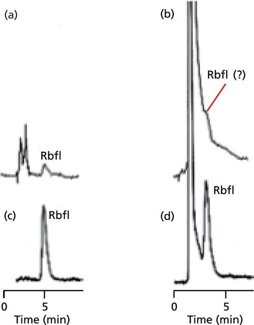
Figure 1: Comparison of UV and fluorescence response for riboflavin (Rbfl): (a,b) UV detection at 365 nm; (c,d) fluorescence detection at 365 nm excitation and 530 nm emission. (a,c) Injection of 5 ng riboflavin standard; (b,d) riboflavin in dog food extract. Cation-exchange separation on a 100 mm x 2.1 mm Zipax-SCX column with water as mobile phase at 1.0 mL/min. Adapted from DuPont data presented as Figure 4.14 in reference 5.
When UV detection is used, most workers avoid derivatization of the analyte because of inconvenience and possible increase in variability of the analytical results. However, it is much more common to use derivatization with fluorescence detection. Derivatization can generate fluorescent analyte molecules, increasing method sensitivity and selectivity. One popular reaction is with o-phthaldialdehyde (OPA), which reacts with primary amines to form fluorescent isoindole derivatives of compounds such as proteins and peptides. This reaction can be done as a precolumn derivatization or on-line as a postcolumn reaction.
Physical Layout
The conceptual schematic of a generic fluorescence detector is shown in Figure 2. An intense lamp is needed to provide excitation energy in the UV and visible ranges. A xenon flash lamp is the typical choice, providing light at wavelengths ranging from 200 nm up to 700–900 nm. If the detector flow cell were a linear design, as is used in the UV detector (for example, Figure 3a in reference 4), the photodetector would have to filter out the light at the excitation wavelength. However, the light emitted in the fluorescence process is emitted in all directions, so monitoring emission at a 90° angle to the excitation wavelength is just as effective-plus it eliminates the problem of interference and minimizes scattered light. (Although not a common design, it is possible to configure the detector with a different cell design so that UV absorbance can be monitored in a straight-through optical path and fluorescence at right angles.) The construction of the flow cell is not as robust as that for a UV detector, and typical pressure limits are 3–35 bar (40–500 psi), so be sure to check the specifications for your detector and ensure that the pressure limits are not exceeded. The photons generated during fluorescence are monitored by a photosensitive device, which could be a photodiode, but more commonly is a photomultiplier tube (PMT).
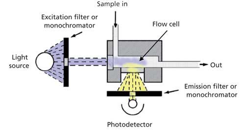
Figure 2: Schematic of a generic fluorescence detector.
The excitation and emission wavelengths typically are selected using a pair of monochromators. The diffraction grating in the excitation monochromator is rotated to select the desired excitation wavelength and direct it through the flow cell. In a similar manner the desired emission wavelength is selected to allow the PMT to monitor the appropriate wavelength. Either or both monochromators can be used in a scanning mode. This process has the same weakness of using scanning with a variable-wavelength detector (see reference 4) because of changing concentration of the analyte during scanning. However, scanning techniques are useful when trying to identify the best excitation and emission wavelengths if these characteristics of the sample molecule are not already known. Alternate designs of detectors have been made in the past in which less-expensive optical filters are used for one or both monochromators, but the most popular instruments today are the dual-monochromator units.
Application and Troubleshooting
The key to effective use of the fluorescence detector is to find the best excitation and emission wavelengths. The excitation maximum for fluorescence and the UV absorbance maximum are usually very close to each other. For this reason, a UV spectrum obtained from a diode-array detector or the literature is a very useful tool to identify the desired excitation wavelength. Typically, a 20-nm bandwidth is specified for the monochromators, so a wavelength setting close to the ideal wavelength should provide an acceptable setting. After the excitation wavelength is selected, the emission wavelength can be scanned to identify the desired setting. For routine operation, the excitation-emission wavelength pair can be set for each peak in a chromatogram and switched during the run to get the best response for each peak.
The process of optimizing the detector settings will depend a bit on the design of the detector, so be sure to consult the operator’s manual that comes with your particular detector-there usually are excellent instructions on how to set up the detector and use its features. I found a free e-book produced by one manufacturer (6) that includes a very useful discussion of fluorescence detection and some of its nuances.
After the excitation and emission wavelengths and other chromatographic conditions are chosen, it is wise to check for any background response, just like you would do for an LC method with UV detection. An example of how background response can differ is shown in Figure 3 (6). In this case, three water sources were chosen-deionized water, water purified with a laboratory water purification system (HPLC-grade), and commercially prepared LC–mass spectrometry (MS)-grade water. For the test of Figure 3, water was run at a constant flow rate and following a short autozero time, the response was recorded using the excitation and emission wavelengths chosen for each of five polynuclear aromatic hydrocarbons in the sample. You can see that the background was much higher for the first and third conditions than for the remaining conditions. Also there was noticeably higher background in all cases when deionized water was used when compared to high performance liquid chromatography (HPLC)-grade or LC–MS-grade water. These results are analogous to those observed for UV detection in that higher-purity reagents give lower background signals. Fluorescence of the analytes as well as background fluorescence can be influenced by the molecular structure of the analyte as well as the chromatographic conditions and column temperature.
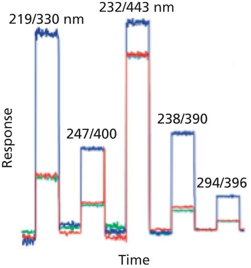
Figure 3: Comparison of background fluorescence of different water sources under various conditions. Blue: deionized water; red: lab-prepared HPLC-grade water; green: commercial LC–MS grade water. In each case, the baseline is autozeroed, then allowed to collect data at the excitation–emission wavelength pair shown above each plateau. Wavelength pairs are those used for analysis of a five-component sample of polynuclear aromatic hydrocarbons. Figure data adapted from Figure 26 in reference 6.
When the chromatograms of Figure 1 were examined earlier, it was seen that background components in the dog food sample interfered with detection by UV (Figure 1b), but the selectivity of fluorescence allowed detection of riboflavin in the presence of these interferences. In some cases, however, interferences in the sample can suppress the fluorescence of an analyte in an analogous manner to ion suppression in LC–MS detection. An interesting example of fluorescence suppression, or quenching, is shown in Figure 4 (7). In this example, naphthalene is injected approximately every 2 min and detected by UV (254 nm) or fluorescence (250-nm excitation, 340-nm emission). Initially the mobile phase is sparged with helium (He) and the baseline is steady with a strong naphthalene response. Next, the mobile phase is sparged with air while injections continue. The UV baseline rises a bit because of UV absorbance of oxygen and the signal rises the same amount. In the case of fluorescence, however, the baseline stays steady, but the signal drops gradually to about 20% of the original signal. This drop results from oxygen quenching the fluorescence of naphthalene under these conditions. When helium sparging is resumed, oxygen is displaced from the mobile phase and both chromatograms return to normal. In practical application, it is unlikely that the changes in the UV chromatogram would be noticed, because it is common to autozero at the beginning of each run, which would mask the observed offset. The fluorescence problem could be a very vexing one to solve. At the time the study was done, it was common to degas solvents with helium, either in a batch mode or continuously. Imagine if the mobile phase were sparged in the morning with helium, then placed on the system. Over the course of the day, air would be absorbed gradually into the mobile phase and the signal would gradually drop. The next day, the pattern would repeat itself. It might take a long time to troubleshoot that problem!
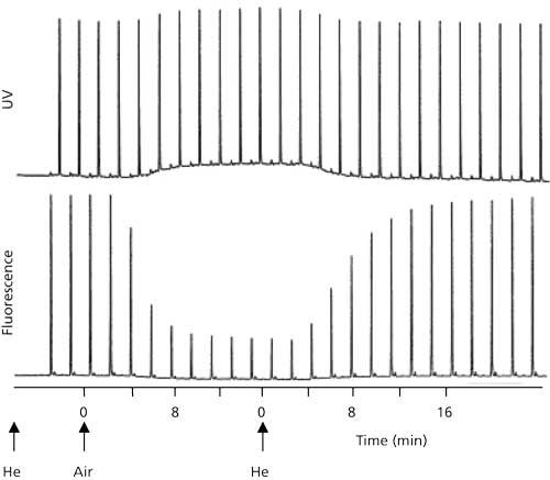
Figure 4: Example of fluorescence quenching of naphthalene because of oxygen dissolved in the mobile phase. Upper chromatogram: UV detection at 254 nm; lower chromatogram: fluorescence with 250-nm excitation and 340-nm emission. Mobile phase is sparged with helium (He) or air, as indicated. Adapted from data of reference 7.
Today most systems use in-line vacuum degassing instead of helium sparging. Vacuum degassing drops the air burden of the mobile phase enough that outgassing problems in the pump or mixer are not important, but it does not selectively remove oxygen from the mobile phase. Oxygen makes up approximately 20% of air, so dissolved oxygen will still remain in the mobile phase, although at a reduced level. It would be interesting to repeat the experiment of Figure 4 using an in-line degasser to see if enough oxygen remained to cause fluorescence suppression. If suppression were observed, it would be a good idea to sparge the mobile phase with helium or nitrogen to displace the oxygen before the in-line degassing took place.
Conclusions
Fluorescence detection can be a powerful tool to increase sensitivity and selectivity of LC analysis for compounds that fluoresce. It can be a good alternative to other detectors for such compounds. I remember a method we developed in our laboratory for a porphyrin drug that strongly fluoresced. Our client insisted that we develop a LC-MS method for it. The method was a nightmare-sample preparation was difficult, ion suppression was prominent, and the signal was weak. When we received clinical samples, the fluorescence of the drug made the plasma visibly green. We had explained to the client that fluorescence with emission at 440 nm gave a stronger and interference-free signal with nothing more than protein precipitation for sample preparation. But the client wanted LC–MS . . . and the client is always right!
References
- J.W. Dolan, LCGC North Am. 34(5), 324–329 (2016).
- J.W. Dolan, LCGC North Am.34(6), 400–407 (2016).
- J.W. Dolan, LCGC North Am. 34(7), 472–478 (2016).
- J.W. Dolan, LCGC North Am. 34(8), 534–539 (2016).
- L.R. Snyder and J.J. Kirkland, Introduction to Modern Liquid Chromatography, 2nd edition (Wiley, Hoboken, New Jersey, 1979).
- H. Franz and V. Jendreizik, Fluorescence Method Development Handbook (Thermo Fisher Scientific, Germering, Germany, 2013) http://www.dionex.com/en-us/webdocs/113591-Handbk-FLD-3000-Method-Develop-AN70302_E.pdf.
- S.R. Bakalyar, M.P.T. Bradley, and R. Honganen, J. Chromatogr. 158, 277–293 (1978).
John W. Dolan

“LC Troubleshooting” Editor John Dolan has been writing “LC Troubleshooting” for LCGC for more than 30 years. One of the industry’s most respected professionals, John is currently the Vice President of and a principal instructor for LC Resources in Lafayette, California. He is also a member of LCGC’s editorial advisory board. Direct correspondence about this column via e-mail to LCGCedit@ubm.com

Polysorbate Quantification and Degradation Analysis via LC and Charged Aerosol Detection
April 9th 2025Scientists from ThermoFisher Scientific published a review article in the Journal of Chromatography A that provided an overview of HPLC analysis using charged aerosol detection can help with polysorbate quantification.
Removing Double-Stranded RNA Impurities Using Chromatography
April 8th 2025Researchers from Agency for Science, Technology and Research in Singapore recently published a review article exploring how chromatography can be used to remove double-stranded RNA impurities during mRNA therapeutics production.


