Hydrogen Carrier Gas and Vacuum Compensation
A look at the effect of choosing hydrogen carrier gas on column selection and when using direct-interface GC–MS
Gas chromatographers are using hydrogen carrier gas more frequently as an inexpensive and a readily available substitute for helium, as well as to gain some performance improvements. In this instalment, John Hinshaw investigates the influence that choosing hydrogen carrier has on column selection and operation with direct-interface gas chromatography–mass spectrometry.
Recently, the use of hydrogen carrier gas in gas chromatography (GC) has been discussed, reviewed, analysed and praised numerous times in this magazine1–4 as well as many other publications. With the prospects of shortages and everincreasing costs for helium, hydrogen offers some desirable economic and logistical advantages, as well as performance changes for columns. The latter topic is the main focus of this instalment, but first let's review some of the economic and logistical benefits and concerns associated with hydrogen use in the laboratory.
Economics and Logistics: First, hydrogen as a replacement carrier gas is less expensive than helium. Switching to hydrogen also offers significant logistical advantages because it makes it possible to reduce the number of tanks of compressed gas in the laboratory, by installing a gas generator instead. In laboratories where multiple GC systems equipped with split inlets and flame ionization detection (FID) systems together consume large quantities of hydrogen gas, the deployment of hydrogen generators is an attractive proposition: The high rate of consumption means an early break-even point on the initial cost of the generators. Also, gas generators allow safety personnel to sleep better knowing that the amount of stored flammable gas is limited and that there are fewer high-pressure gas cylinders chained to the walls. It can be argued that the presence of any high-pressure gas cylinders represents a greater hazard than that imposed by a self-generated hydrogen carrier. This argument comes to a logical conclusion with the installation of zeroair generators, in addition to hydrogen generators, that clean up compressed air for use with FID systems. Thus, switching from helium to hydrogen means that high-pressure cylinders can be eliminated for routine GC–FID applications as well as for gas chromatography–mass spectrometry (GC–MS) systems that use electron ionization (EI). Chemical ionization (CI) does require a cylinder of collision gas such as methane or ammonia, neither of which are particularly amenable to in-situ generation.
Safety: Although switching to hydrogen carrier can improve safety by making it possible to reduce the number of high-pressure gas cylinders in the laboratory, hydrogen does pose safety risks. Reasonable precautions should be taken to prevent and to detect the accumulation of hydrogen from multiple split vent flows or other significant sources, whether using tanks or gas generators. The built-in leak detection features of modern electronic pressure control (EPC) pneumatic systems along with appropriate awareness and procedural training for those who use hydrogen in the laboratory can reduce the likelihood of an accident to low levels. The best practice is to install a hydrogen sensor high up in each laboratory. You may also want to consider installing small dedicated hydrogen sensors in the GC ovens, especially if not using an EPC system with hydrogen-leak shutdown.
Performance: Beyond the economic and logistical gains to be obtained from gas generators and hydrogen, it has some chromatographic performance advantages over helium carrier. There is less dependency of column performance on the average carrier gas linear velocity with hydrogen compared with helium. The range of linear velocities over which column efficiency lies close to the optimum for any particular solute is broader than with helium. This comparison has been made many times before. Two years ago "GC Connections"4 showed an example where a solute with k = 10.0 on a 50 m × 0.25 mm column at 100 °C had an optimum average linear velocity range of 18–45 cm/s for helium versus 25–65 cm/s for hydrogen, where "optimum" was defined as the region in which the plate height lies within 25% of its minimum. This wider optimum range gives chromatographers more latitude in setting average velocities with hydrogen carrier. The optimum range for hydrogen covers faster linear velocities too, which can yield higher analysis speeds because peaks can be eluted in less time without sacrificing as much performance as when pushing helium carrier to the same higher speeds. Hydrogen also has the advantage of requiring lower inlet pressures to deliver a given average velocity, due to its reduced viscosity.
All is not so simple, however, when moving an existing method from helium to hydrogen carrier either with conventional or MS detectors; there are several key considerations that GC and GC–MS users should understand.
Pressure and Column Length
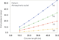
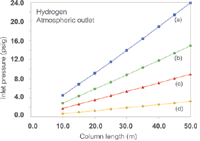
The effects of switching to hydrogen carrier with the column outlet at atmospheric pressure are well known. Figure 1 shows a family of curves that relate the inlet system gauge pressure (the EPC pressure setting or readout) to column length for a series of column inner diameters with a 40 cm/s average linear velocity at 50 °C. Figure 2 shows a similar plot for the same series of columns with hydrogen carrier gas: The overall decrease in the pressure drop required to reach 40 cm/s is evident. The pressure needed to drive the carrier gas at 40 cm/s through an example 25 m × 0.25mm column decreases from 16 psig (110 kPa) for helium to 7.3 psig (50 kPa) for hydrogen, while the column flow decreases from 1.9 to 1.5 mL/min. (Flow-rates have been adjusted to 20 °C for these examples. Some EPC systems use a 0 °C reference temperature and will display slightly different pressures, velocities and flowrates. For simplicity when considering multiple column diameters, the film thickness was set to 0.0.)

Figure 1: Plots of inlet pressure against column length, with helium carrier gas and vacuum compensation off. Column inner diameters (mm): (a) 0.20, (b) 0.25, (c) 0.32 (d) 0.53; column temperature: 50 °C; average linear velocity: 40 cm/s.
EPC systems make it easy to establish the same initial velocity or flow in this situation; I prefer to keep the starting velocity constant. Consider that maintaining the flow at 1.9 mL/min while changing to hydrogen carrier will cause the initial average velocity to increase from 40 cm/s up to 50 cm/s, at a pressure drop of 8.9 psig (61 kPa). This increased velocity in turn may shift relative peak positions with temperature-programmed elution to a greater degree than is desirable. For better control of the resulting separation, try using Method Translation Software (Agilent Technologies, Santa Clara, California, USA) or a similar utility. This application also considers the column temperature programme when suggesting adjustments to a GC method being moved to hydrogen carrier gas — as well as for many other situations including switching to an MS detector. In this case, it suggests that a slightly higher temperature programme rate plus a shorter initial hold time would preserve peak elution order. In all cases, any time that a major change is made to an existing method the identities and quantitative behaviour of all solutes must be revalidated to be sure that the new method produces comparable results.

Figure 2: Plots of inlet pressure against column length, with hydrogen carrier gas and vacuum compensation off. Column inner diameters (mm): (a) 0.20, (b) 0.25, (c) 0.32 (d) 0.53; column temperature: 50 °C; average linear velocity: 40 cm/s.
Considerations for Direct-Interface GC–MS
In direct-interface GC–MS, the end of the GC column is inserted directly into the ion source. The column exit sits in the source vacuum and this low pressure strongly influences the movement of carrier gas and solutes through the column compared to when the outlet is at atmospheric pressure. In addition to influencing the chromatographic separation, all of the carrier gas enters the mass spectrometer's source and must be pumped away by the MS vacuum system. The type of carrier gas — helium or hydrogen — significantly influences the vacuum characteristics of the source as well and may also affect solute ionization.
Carrier Gas Flow Under Vacuum Outlet Conditions
For those readers who are interested, here is some theory that pertains to the effects of placing the column exit at vacuum on the movement of carrier gas through the column.
The pressure drop across a column is the difference between the inlet and outlet absolute pressures:

When the outlet of the column is at the ambient atmospheric pressure then the pressure drop is equal to the control point of a split-inlet pressure controller that maintains its set pressure in reference to the atmospheric pressure. For example, if the absolute inlet pressure were 44.1 psia (303 kPa) and the outlet pressure were 14.7 psia (101 kPa) then the pressure drop would be the difference, 29.4 psig (202 kPa), and an EPC split inlet controller would read this value for the inlet pressure. This is the normal situation when using FID or most other non-MS detection methods.
A pressure drop Δp across a column produces an average linear gas velocity u-mean through the column that can be expressed as follows:

Here, dc is the column inner diameter, L is the column length, η is the carrier gas viscosity at the column temperature, and j' is a pressure correction factor:

This factor, termed "j-prime," adjusts for the influence of carrier gas compressibility on the flow of gas through the column, specifically its influence on the average velocity. Don't confuse it with the "j" factor that relates the average velocity to the outlet velocity on the basis of the volumetric expansion of gas as it transits the column from the inlet to the outlet pressure. The variable P is the pressure ratio of the column:

In the example above with the column outlet at atmospheric pressure, P equals 3.0 and j' equals 0.9231. At this modest pressure ratio the influence of j-prime on the average velocity predicted from the pressure drop is less than 10%, which means that about 10% higher pressure would be required to achieve the desired velocity than predicted without this factor. This influence exceeds 10% as the pressure ratio goes higher than 4.0, and it is incorporated into EPC systems that calculate the apparent average linear velocity of a column from the pressure drop and other variables.
When the column exit is placed under vacuum, the pressure drop across the column is essentially equal to the absolute inlet pressure: The pressure drop in our example case increases from 29.4 psi (202 kPa) to 44.1 psi (303 kPa). Most EPC pressure controller displays — and all mechanical controller readouts — will continue to show 29.4 psig (202 kPa), however, because the pressure controller operates relative to ambient pressure and not in relation to a vacuum. EPC systems determine the absolute pressure drop by adding the ambient atmospheric pressure (from a separate sensor) to the controller's pressure level and then use it to estimate the column average linear velocity and flow using similar equations. Any discrepancies between the actual column dimensions and the values entered into the EPC system will cause the flow and velocity readouts to deviate from the true values as measured by independent means such as with a flow meter or from the unretained peak time.
The pressure ratio approaches infinity as the outlet pressure approaches zero, and the limit of j-prime approaches 0.75:

so for vacuum outlet operation:

This equation is used to calculate the average velocity under vacuum conditions.
Reducing the Column Outlet Pressure
Now consider what happens when the column outlet pressure is reduced to near zero in a direct-interface MS ion source while the inlet pressure and carrier gas type are left unchanged: The increased pressure drop across the column causes both the velocity and flow to increase. For the example 25 m × 250 μm column at 40 cm/s, the average velocity increases to 60 cm/s and the flow-rate increases to 2.5 mL/min when the absolute outlet pressure drops to zero.
The resulting increased flow and velocity are not necessarily desirable in this situation. Most bench-top MS detectors can pump 2–4 sccm of helium carrier gas, and somewhat less with hydrogen, depending on the capacity of the turbomolecular or diffusion pump. Higher flow-rates easily can exceed the pumping capacity, and the consequent higher source pressures may reduce EI efficiency, reduce the mass resolution and produce unwanted fragments from extra collisional effects that may degrade library search results. On the peak separation side, changes in the velocity or flow with temperatureprogrammed elution may cause peaks to shift relative to each other or even to be coeluted or to reverse their elution order — the same kind of effects seen when modifying a method where the column outlet remains at atmospheric pressure.
Therefore, adjustments to the columninlet pressure settings are also in order when a separation is moved from a detector that operates near atmospheric pressure to an MS detector, or when changing an existing MS detection method from helium to hydrogen. Chromatographers can use built-in EPC calculations to establish the inlet-pressure setting that produces the same constant flow or average velocity at the starting oven temperature with a vacuum outlet, as was discussed earlier for a configuration without a vacuum outlet. For example, the above column at 50 °C with helium carrier requires about 5.9 psig (41 kPa) for the same average velocity of 40 cm/s at vacuum outlet conditions as was produced by a 16-psig (110 kPa) pressure with the outlet at atmospheric pressure. At the lower outlet pressure, the column flowrate drops to 1.1 mL/min at the reduced inlet pressure set point.
Here too, keeping the initial velocity the same while changing from atmospheric to vacuum outlet will help preserve peak elution order. If the same constant flow-rate of 1.9 mL/min was required in translation, an inlet pressure of around 12.3 psig under vacuum outlet conditions would yield the same flow as did the original 16.1-psig inlet pressure with the outlet at atmospheric pressure. This does, however, increase the initial average velocity to 53 cm/s, which may affect the separation more than desired. Again, a method translation utility will help to establish the closest-matching conditions.
Going Under Water
When working with a direct GC–MS interface, chromatographers should be aware that many common combinations of column diameter and length lead to the EPC system demanding a negative, subatmospheric inlet pressure. The situation occurs when the required pressure drop from the column inlet to the vacuum outlet is less than atmospheric pressure. The principal symptom of this situation is the EPC channel not becoming ready, the inlet pressure at or slightly below zero, and a positive flow and velocity readout.
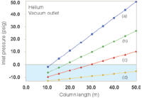
This "underwater" condition of negative inlet pressures arises readily within our collection of example columns. Figure 3 shows what happens to the inlet pressures when the outlet pressure goes to vacuum with helium carrier gas at 40 cm/s. The graphed data suggest that a 530 μm i.d. column will not be useful at all for direct-interface GC–MS, while 320 μm columns need a minimum length of 40 m, 250 μm columns should be longer than 25 m, and 200 μm columns should be longer than 15 m. These column lengths were selected by keeping in mind that the inlet system needs to operate at a pressure above ambient: Zero inlet gauge pressure is not usable. Flow-rates under these conditions run between about 1.0 and 2.2 mL/min and should not be problematic for the MS vacuum system, although the longer 320 μm columns would operate better with a higher capacity vacuum pump that can remove up to 4 mL/min of carrier gas. The higher capacity pump is also better suited to hydrogen carrier gas.

Figure 3: Plots of inlet pressure and column length, with helium carrier gas and vacuum compensation on. Column inner diameters (mm): (a) 0.20, (b) 0.25, (c) 0.32 (d) 0.53; column temperature: 50 °C; average linear velocity: 40 cm/s. The blue shaded area designates negative inlet pressures.
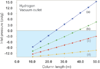
With hydrogen carrier at 40 cm/s this underwater zone eliminates a larger portion of the column collection, as shown in Figure 4. Here, only 200 μm i.d. columns of 30 m and greater length or 50 m × 250 μm columns are usable, while none of the selected 320 μm or 530 μm columns call for positive inlet pressures under these conditions. If the average velocity is increased to 60 cm/s then the set of useful columns for hydrogen carrier is much the same as with helium carrier at 40 cm/s, but in that case a translation from helium conditions to hydrogen conditions that yield a similar peak separation may prove difficult to achieve. Simply operating wider-bore columns at a low positive inlet pressure will certainly create very high average linear velocities that result in drastically reduced separation efficiency, and also such a set-up can provide too much carrier gas flow for the mass spectrometer's vacuum system to pump away effectively. For example, even a 50 m × 530 μm column when operated with just 3.0 psig (20 kPa) of hydrogen carrier pressure and a vacuum outlet will produce an average velocity of 165 cm/s and a flow of almost 18 mL/min, far above the pumping capacity of benchtop mass spectrometers.

Figure 4: Plots of inlet pressure against column length, with hydrogen carrier gas and vacuum compensation on. Column inner diameters (mm): (a) 0.20, (b) 0.25, (c) 0.32 (d) 0.53; column temperature: 50 °C; average linear velocity: 40 cm/s. The blue shaded area designates negative inlet pressures.
There are at least two alternatives to a direct GC–MS interface that help alleviate the underwater effect: an opensplit interface or a vacuum restrictor arrangement. In an opensplit interface the column exit remains close to atmospheric pressure while additional make-up gas flow surrounds it. A restrictor tube transfers a fixed flow of column effluent and make-up gas to the MS source from the opensplit interface while any remaining gas is vented. This arrangement keeps the column exit close to atmospheric pressure and enables most opentubular columns to work with an MS detector. The portion of the column effluent that enters the MS source depends both on the column flow and make-up flow, however, so constant-flow operation is preferred. Some fraction of the solutes does not enter the source, which reduces the sensitivity in proportion. An open-split interface is more difficult to maintain, but as a plus it does enable a column change without having to vent the MS detector.
It is also possible to connect a restrictor at the column outlet with a zero-dead-volume connector and then pass the restrictor through a direct interface into the MS source. The restrictor length and inner diameter need to be chosen according to the column flow-rate, so that the column outlet pressure will be high enough to bring the inlet pressure above atmospheric levels. This arrangement is comparatively simple, but it will cause EPC display of the column flow and velocity to be in error. The absolute pressure of the column exit depends on the column flow-rate: Higher flows will increase the outlet pressure. This behaviour is not built into EPC systems that assume the column outlet remains at either atmospheric pressure, zero pressure or a fixed operator-entered pressure. This restrictor arrangement does work well with 0.53 mm i.d. columns that receive carrier gas from a directly connected mass flow controller, as long as the flow-rate does not exceed the pumping capacity of the mass spectrometer's vacuum system.
Conclusion
Reasons for switching from helium to hydrogen carrier gas include cost-savings and safety. The choice of generating hydrogen carrier gas on-site is attractive in many cases, and it has the added benefit of not requiring users to store, manage and handle gas cylinders. Hydrogen safety can be managed with the right combination of procedures, education and equipment.
Several issues arise when switching to hydrogen carrier. For all situations the effects of changes in the column flow and velocity profile on the separation must be evaluated carefully and then accommodated. Method revalidation is usually necessary. When using an MS detector, the carrier gas pumping capacity of the detector and the effect of vacuum outlet operation on column inlet pressures as well as on the flow and velocities must be accounted for. A direct-interface GC–MS interface will work well for narrowerbore columns but an opensplit interface may be a better solution for wider-bore columns.
"GC Connections" editor John V. Hinshaw is senior research scientist at Serveron Corp., Hillsboro, Oregon, USA and a member of LCGC Europe's editorial advisory board. Direct correspondence about this column to LCGC Europe editor, Alasdair Matheson, at amatheson@advanstar.com
References
1. R.J. Bartram and P. Froehlich, LCGC N. Am., 28(10), 890 (2010).
2. J.V. Hinshaw, LCGC N. Am., 28(3), 218 (2010).
3. J. Heseltine, LCGC N. Am., 28(1), 16 (2010).
4. J.V. Hinshaw, LCGC N. Am., 26(11), 1100 (2008).

Detecting Hyper-Fast Chromatographic Peaks Using Ion Mobility Spectrometry
May 6th 2025Ion mobility spectrometers can detect trace compounds quickly, though they can face various issues with detecting certain peaks. University of Hannover scientists created a new system for resolving hyper-fast gas chromatography (GC) peaks.
Altering Capillary Gas Chromatography Systems Using Silicon Pneumatic Microvalves
May 5th 2025Many multi-column gas chromatography systems use two-position multi-port switching valves, which can suffer from delays in valve switching. Shimadzu researchers aimed to create a new sampling and switching module for these systems.
New Study Reviews Chromatography Methods for Flavonoid Analysis
April 21st 2025Flavonoids are widely used metabolites that carry out various functions in different industries, such as food and cosmetics. Detecting, separating, and quantifying them in fruit species can be a complicated process.

.png&w=3840&q=75)

.png&w=3840&q=75)


.png&w=3840&q=75)


.png&w=3840&q=75)


