Gas Cylinder Setup and Use
LCGC North America
What you need to know about pressure regulators, gas filtration, and gas fittings - and when to retire your cylinders
This month's installment discusses the laboratory deployment of gas cylinders with appropriate pressure regulators, gas filtration, and gas fittings, as well as the question of cylinder retirement.
Aprevious "GC Connections" installment (1) discussed the intake and disposition of compressed gas cylinders, including verifying gas cylinders and their content upon receipt, safely moving and securing them in place, and organizing them by their current use. After cylinders are in place in the laboratory, the next steps are to attach appropriate gas regulators, tubing, filters, and fittings to bring the high-purity gas supplies to one or more gas chromatographs.
Pressure Regulators
Pressure regulators are unsung heroes in the laboratory. They accomplish the expansion of high-pressure cylinder gases from dangerous levels to what can reasonably be handled by laboratory instruments while maintaining nearly constant output pressures and — if correctly matched to the application — not contaminating the gas stream. Of course, pressure regulator selection, installation, and maintenance are essential for obtaining the best performance. But before discussing the whys and whats of regulators, here's a brief description of how they work.
In Control
Laboratory pressure regulators are designed to expand gases from cylinder pressures as high as 3000 psig (20.7 MPa) down to operating pressures as low as 10–20 psig (150–275 kPa). Gas-tank regulators are mechanical devices with springs, screws, and a counterbalancing diaphragm. Electronic pressure control (EPC) has not yet found its way into the tank realm in any significant way, although some laboratory hydrogen generators incorporate EPC. Electronic pressure control of in-instrument gases will be covered in a future "GC Connections" installment.
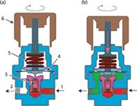
Figure 1 shows a simplified diagram of a typical single-stage mechanical gas-pressure regulator such as what is found at the gas tank or sometimes in-line as part of a manifolded gas distribution setup. The regulator consists of a two-piece sealed housing with the internal volumes separated by a flexible diaphragm. The outlet gas pressure exerts force on one side of the diaphragm and a spring pushes in the opposite direction. The amount of force exerted by the tensioning spring on the diaphragm determines the output pressure level. A pressure adjustment knob turns a screw that increases or decreases the force on the spring and diaphragm.

Figure 1: Mechanical gas-pressure regulator: (a) The adjustment knob is fully withdrawn and no pressure is applied to the tensioning spring - the poppet valve is closed and no gas flows. (b) The adjustment knob is turned clockwise and advanced into the regulator. There is tension on the spring so that the poppet valve is contacted and gas flows to the outlet. 1 = inlet connection, 2 = outlet connection, 3 = poppet valve, 4 = flexible diaphragm, 5 = tensioning spring, 6 = adjustment knob. The inlet gas chamber is colored red; the output chamber with pressure-controlled gas is shown in green.
In Figure 1a, the adjustment knob is fully turned out and the spring exerts no force on the diaphragm: The pressure on the outside of the diaphragm is equal to ambient pressure. Gas at the tank pressure has entered the regulator at the inlet connection, and the poppet valve below the diaphragm is fully seated so that no gas flows through it. The upper shaft of the poppet is not in contact with the actuating seat that is attached to the diaphragm.
In Figure 1b, the adjustment knob has been turned clockwise and its shaft has moved downward to exert force on the spring and diaphragm. This movement has caused the actuating seat under the diaphragm to contact the upper shaft of the poppet valve and move it downward, which in turn unseats the poppet and allows gas to flow into the outlet chamber. As pressure builds up in the outlet chamber, the diaphragm is forced upward against the tensioning spring. The regulator settles into a constant outlet pressure when the spring force and the pneumatic force are balanced as gas flows out of the regulator.
As the output gas flow increases, the poppet valve opens up to sustain the output pressure balance against the tensioning spring. Conversely, as the output gas flow decreases the poppet valve moves upward and restricts gas flow, again so that the output pressure is maintained. If the outlet flow goes to zero, the poppet will seal off the inlet.
Nonlinear Effects
Mechanical pressure regulators are subject to a few side effects with which many gas chromatographers are familiar. A nonideality occurs when the outlet flow rate increases so much that the poppet valve is forced fully open. Any additional flow demand will cause the outlet pressure to drop well below its set point. In this condition, the regulator is unable to supply enough gas and can be said to be choked off. The basic capability of a regulator to deliver steady pressure control at high flows is encapsulated in its flow coefficient, or Cv. The flow coefficient is measured with the regulator fully open, however, and does not represent a realistic situation for gas chromatography (GC) applications. Most tank regulators in GC laboratories have maximum flows of tens of liters per minute or more, but this situation rarely occurs with GC instruments that consume gas at a few hundred milliliters per minute or less. The Cv coefficient is not relevant for normal GC installations with the types of regulators that are usually supplied for GC applications.
The outlet pressure will decrease somewhat as flows increase between the minimum flow and the choke-point flow: This effect is termed droop. The poppet valve must move toward a more open position at higher flows, which in turn displaces the inherently nonlinear diaphragm and tensioning spring toward a lower set-point pressure. Droop causes gas pressures to change slightly at the GC instrument gas inlet connection as conditions change, such as when the inlet mode is changed from split to splitless in some instruments.
The GC instrument's internal carrier-gas control system will compensate for droop if the maximum column inlet pressure to be used is set lower than the tank pressure regulator output by at least 20%. For example, if the maximum carrier-gas pressure is 70 psig (482 kPa) then the tank regulator should be set to at least 85 psig (586 kPa). Normally, the manufacturer's recommended incoming carrier-gas pressure will be sufficient, but operators need to be aware of the necessity to increase supply pressures if higher inlet pressures are to be used — for example, for some types of high-speed chromatography.
A third nonideal effect is the dependency of the output pressure on the incoming tank pressure, sometimes called the supply-pressure effect. As the cylinder pressure decreases the output pressure will start to increase, roughly as a small percentage of the decrease in supply pressure. For example, if the tank pressure declines by 1000 psi and the output pressure increases by 10 psi then the supply-pressure effect is 1%.
This increase in output pressure occurs because the input gas pressure exerts some force on the poppet valve, which, while small in comparison to the tensioning spring–diaphragm, constitutes a small reduction in the overall output pressure. Lower supply pressures then cause the output pressure to increase slightly as the counter force on the poppet lessens. The degree of supply-pressure effect depends on the regulator design: A high-quality regulator will incorporate some features to minimize it.
In extreme cases the output pressure rise could exceed a safe limit. The best solution for controlling the supply-pressure effect is to use dual-stage regulation from the tank to the instrument. Usually this approach involves using a single gas-regulation device at the gas tank that incorporates two regulator stages connected in series internally. The first stage reduces the pressure to an intermediate level of 300–500 psi, and the second drops the pressure to the service level. Often when a manifolded gas supply system is used, the first regulation stage is installed at the tank and a second regulator is installed in-line immediately upstream from one or more instruments.
In either case, the supply effect is now well controlled. If the first regulator has a supply-side effect of 5%/psi and the second has a supply-side effect of 1%/psi, then the overall effect will be 5% of 1%, or only 0.05%, until the tank pressure reaches the intermediate pressure. From that point down to a final pressure of 100 psig, the supply effect will be equal to that of the second stage. So when the cylinder pressure drops by 2300 psi across its full range from 2600 psig down to the intermediate 300 psig the output pressure from a high-quality regulator would be expected to increase less than 1 psi. For the remaining 200 psi the first stage no longer functions, so the output pressure would increase by an additional 2 psi for a total pressure increase of around 3 psi as the cylinder is depleted.
Many regulators incorporate a safety relief valve on the low-pressure side. This valve will open at a predetermined high pressure and help limit the high pressures that could otherwise be applied to the downstream equipment should the internals of the regulator fail. Such failures are rare and usually are caused by misuse or contamination. To ensure long regulator lifetimes, the following practices should be employed:
- Never allow a pressure regulator to be back-pressurized through the outlet connection.
- Ensure the cleanliness of the high-pressure side tank connection. Check for the absence of dust and particulates when connecting the regulator — but never open the tank valve with no regulator attached in a misguided attempt to blow off the seat!
- Never over-compress the diaphragm and spring by turning the pressure knob fully toward higher pressure levels. Many high-quality regulators incorporate internal stops that prevent over-compression, but I have seen several instances where such damage has occurred.
Evidence of an internal failure resulting in high pressures at the outlet can be found when the outlet pressure gauge has been over-wound and shows a positive offset at zero pressure. Immediately take out of service, label as broken or defective, and dispose properly of any compromised regulators. Using such defective devices creates an unacceptable safety hazard.
Keeping It Clean
In addition to delivering as constant an output pressure as possible over the life span of a gas cylinder, a pressure regulator must not add any significant amount of other gases or contaminants. The gas stream in a regulator is exposed to a variety of materials, including the internal seals, the poppet seat, the diaphragm, and the other internal areas. The types of materials and their cleanliness are crucial factors for maintaining gas purity as it passes through. Counter to intuition, even though the inside of the regulator is at elevated pressures, nitrogen, water, and oxygen can leak into the gas stream from the atmosphere. The sealing materials between the inside of the regulator and the atmosphere determine how much leakage will occur, assuming that there are no overt leaks because of defective assembly or poorly executed connections to and from the regulator.
For general GC use, high-purity models for noncorrosive service with a brass body, stainless-steel diaphragm, fluoropolymer seats and seals, and a packless outlet valve are appropriate. For high-sensitivity applications such as GC–mass spectrometry (MS), electron-capture detection (ECD), or other high-performance applications, upgrading the body material to stainless steel can help ensure a higher level of carrier-gas purity because of more-stringent cleaning during assembly along with the accompanying incremental improvements in the other internal materials. Regulators rated for corrosive service are unnecessary for GC consumable gases, but they may be appropriate for certain calibration gases and sample streams.
Regulator cost is related to both the gas purity rating as well as the pneumatic performance. Very-low-cost regulators are generally not appropriate for GC use. Chromatographers should pay attention to regulator specifications and choose those that are suitable for GC applications, following the manufacturer's requirements rather than trying to save a little by opting for less-expensive gas control devices.
Filters
Proper filtration of GC gases is the stop-gap that keeps small levels of contaminants that originate in regulators, fittings, and tubing from becoming big problems. Filters are not suitable as cleanup devices for poor quality gas-cylinder contents, inexpensive contaminated tubing, or low-quality regulators. Carrier gas from a less-expensive four-nines (99.99%) helium cylinder will not be redeemed to six-nines (99.9999%) levels by the use of in-line oxygen, water, and hydrocarbon filters. Filters can restore the quality of lightly contaminated gases, but do not have the capability to clean up intrinsically contaminated gases on the fly. A recent "GC Connections" installment addressed the specific types of filters that are recommended for various GC inlets, columns, and detectors (2).
The Right Connection
Along with selecting an appropriate dual-stage regulation scheme, the correct fittings must be used at the inlet and outlet of a regulator before it can be put into use. Pressure regulators usually are supplied with a high-pressure inlet fitting that will only connect to a matching fitting on the tank — they are ordered for a specific gas or gas type such as helium and nitrogen, air, or hydrogen. The exact fittings for carrier, detector, and calibration gases vary by country and region, so chromatographers should refer to local regulations and to their gas suppliers for the correct information.
Changing an existing regulator from one inlet fitting to another is not recommended. The risks of not attaching the high-pressure connection correctly and damaging the regulator are not offset by the relatively small cost of procuring a set of specific regulators for individual gas use.
The outlet fitting of the regulator must match the size and type of downstream tubing, both diameter and material. Don't mix brass fitting nuts with stainless steel fittings, for example, and always make fresh connections by cutting the tubing and starting over if there is any doubt about reusing a connection. Be sure to follow the fitting manufacturer's exact instructions when making new or reusing tubing or pipe connections, and use available fitting-specific gauges to check for proper assembly. Over-tightening a fitting is the number one mistake that inexperienced chromatographers commit in this area.
Retirement
A gas cylinder is ready for retirement when its pressure has decayed to a level of around twice the regulated downstream pressure. For example, a helium cylinder that supplies 80 psig should be retired as soon as the internal pressure drops to 160 psig. Laboratory staff should check cylinder pressures weekly to ensure that none drop so low that the downstream pressure starts to decay, thereby compromising the attached instruments' performance.
On behalf of gas suppliers everywhere, please be sure to leave some positive pressure in a retired cylinder when it is returned. When the supplier receives a cylinder with the valve closed and significant internal pressure they gain some assurance that the remaining contents are intact and probably not seriously contaminated. Although the suppliers cannot assume zero contamination, this is a much better cylinder state than no pressure, negative pressure, or, worst of all, an open cylinder valve.
I recommend installing a purge tee fitting and valve at the outlet of carrier-gas regulators. This accessory permits clean carrier gas to be isolated in the downstream tubing while changing a cylinder, and it allows the regulator to be purged of the air that inevitably will enter during a changeover. The alternative of pushing a slug of room air into the tubing will shorten the lifetime of the carrier gas oxygen and water filters.
The Inside Story
Now that we have followed GC gases from their origins — such as the formation of helium from radioactive decay in the earth's crust — to separation, purification, and the supply chain that brings them to the laboratory, captured in high-pressure cylinders or perhaps liberated on-demand, it's time to return to the gas chromatograph itself and trace the gases' paths through the pneumatic controls, inlets, columns, and detectors. The next installment of "GC Connections" will visit electronic pneumatic pressure control for carrier and detector gases to see how modern GC systems combine theory with practical considerations to yield optimized performance with a wide range of column dimensions and detector types.
References
(1) J.V. Hinshaw, LCGC North Am. 32(3), 194–199 (2014).
(1) J.V. Hinshaw, LCGC North Am. 31(1), 36–44 (2013).
John V. Hinshaw "GC Connections" editor John V. Hinshaw is a Senior Scientist at Serveron Corporation in Beaverton, Oregon, and a member of LCGC's editorial advisory board. Direct correspondence about this column to the author via e-mail: lcgcedit@lcgcmag.com.

John V. Hinshaw

New Study Reviews Chromatography Methods for Flavonoid Analysis
April 21st 2025Flavonoids are widely used metabolites that carry out various functions in different industries, such as food and cosmetics. Detecting, separating, and quantifying them in fruit species can be a complicated process.
University of Rouen-Normandy Scientists Explore Eco-Friendly Sampling Approach for GC-HRMS
April 17th 2025Root exudates—substances secreted by living plant roots—are challenging to sample, as they are typically extracted using artificial devices and can vary widely in both quantity and composition across plant species.
Sorbonne Researchers Develop Miniaturized GC Detector for VOC Analysis
April 16th 2025A team of scientists from the Paris university developed and optimized MAVERIC, a miniaturized and autonomous gas chromatography (GC) system coupled to a nano-gravimetric detector (NGD) based on a NEMS (nano-electromechanical-system) resonator.
Miniaturized GC–MS Method for BVOC Analysis of Spanish Trees
April 16th 2025University of Valladolid scientists used a miniaturized method for analyzing biogenic volatile organic compounds (BVOCs) emitted by tree species, using headspace solid-phase microextraction coupled with gas chromatography and quadrupole time-of-flight mass spectrometry (HS-SPME-GC–QTOF-MS) has been developed.


