Gas Chromatography and Ion Mobility Spectrometry: A Perfect Match?
Over the past few decades, their outstanding sensitivity and quick response times have allowed ion mobility spectrometers (IMS) to become increasingly popular detectors for gas chromatographs (GC). In this manuscript, we discuss the basic operating principle of IMS, its resulting strengths and weaknesses, and why both perfectly align with the capabilities and requirements of gas chromatographs. This is combined with basic advice for setting up GC-IMS couplings and an outlook on some future developments.
Ion mobility spectrometers (IMS) separate and characterize ions based on their motion through a neutral gas under the influence of an electric field. Thus, one could shrewdly argue that the first GC-IMS coupling was operated by James Lovelock when introducing the electron capture detector (ECD) (1,2). In the ECD, initial high-energy electrons create free thermalized electrons, which can be captured by analyte molecules with high electron affinity contained in the gas stream sweeping through the detector cell, forming negatively charged analyte ions. This electron capture process is extremely efficient, leading to the well-known excellent sensitivity of the ECD especially for halogenated analytes (3). A simplified schematic with parallel electrodes for better visibility is shown on the left in Figure 1. When a voltage pulse is applied between the two electrodes, the extremely mobile electrons follow the electric field to the detector, while the less mobile analyte ions either are carried out of the ECD by the gas stream or are lost to recombination with positive ions. This way, any electron-capturing analyte molecule present in the gas stream reduces the current measured by the current amplifier attached to the detector electrode. Thus, an ECD actually performs a primitive mobility measurement, being only able to separate the extremely mobile electrons from the much less mobile ions. Using this rather unusual point of view, the working principle and advantages of IMS can be easily understood.

 with parallel electrodes; and (b) a drift tube ion mobility spectrometer with a field-switching ion shutter. Note that neither design represents the most common variants in practice, but allow for an easily understandable comparison. See Figure 3 for a more detailed discussion of IMS design.")
FIGURE 1: Comparison between the concepts of an electron capture detector (a) with parallel electrodes; and (b) a drift tube ion mobility spectrometer with a field-switching ion shutter. Note that neither design represents the most common variants in practice, but allow for an easily understandable comparison. See Figure 3 for a more detailed discussion of IMS design.
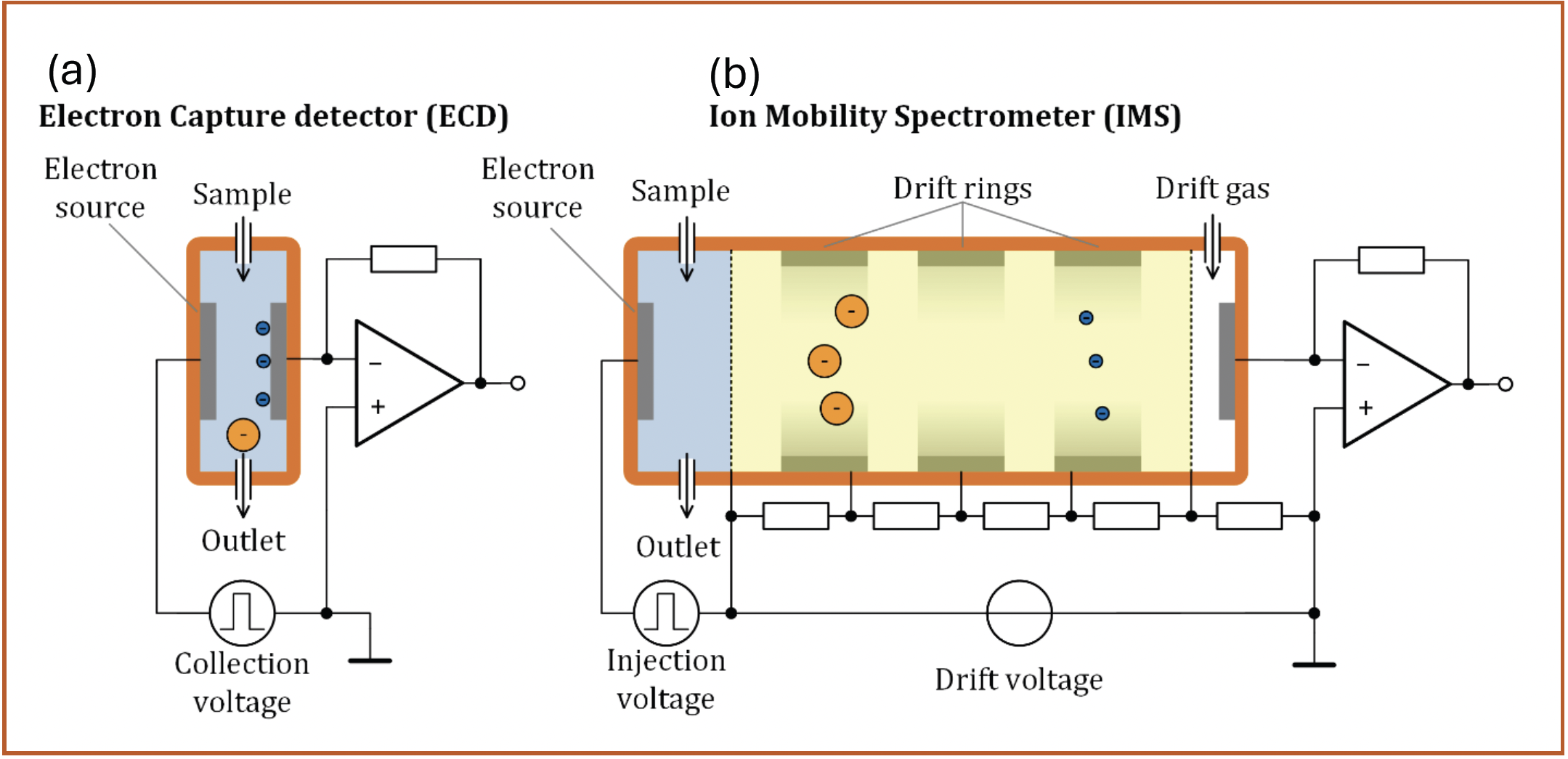
Although there are dozens of different IMS variants (4,5), we will use a drift tube IMS with a field switching ion shutter (6) as shown on the right in Figure 1 for the comparison. Compared to the parallel plate ECD, it essentially adds the yellow drift region, which is continuously swept by a clean drift gas to prevent further reactions. Inside the drift region exists a constant electric field generated by a resistive voltage divider between the ionization region and detector electrode. However, this seemingly simple addition leads to a major difference in operating principle. By using a higher and longer voltage pulse, all ions and electrons that have been previously generated are injected into the drift region. They traverse the drift region at their characteristic drift velocities, and the ion current arriving at the detector is plotted over the time elapsed since the injection, giving the ion mobility spectrum. Containing several Gaussian peaks that mark the arrival of the different ion species, its appearance is similar to a gas chromatogram, and was, in fact, originally called a plasma chromatogram (7). Therefore, the IMS is able to differentiate various ion species from each other, and thus leads to three major advantages over the ECD while maintaining the excellent sensitivity allowed by the ionization principle. Over the past decades, several research groups have compared the analytical performance of IMS and ECD in various applications (8–10).
- IMS add a second separation dimension that is orthogonal to the GC and operates on a millisecond timescale. This provides 2D spectra as shown in Figure 2 (IMS drift time over GC retention time), similar to those from GC×GC. Because of the high repetition rate of the IMS, all peaks that are eluted from the GC can be continuously analyzed, allowing for easy reconstruction of the peaks in GC direction. Typically, even several IMS spectra can be averaged together to improve the signal-to-noise-ratio.
- As the mobility difference between protons (or more accurately protons clustered with water molecules) and positive ions is much less than the mobility difference between electrons and negative ions, it is not possible to build a variant of the ECD that detects analytes with high proton affinity instead of analytes with high electron affinity. IMS are able to resolve this much smaller mobility difference, and can therefore detect both analytes with high proton affinity and analytes with high electron affinity with the sensitivity known from the ECD.
- Unlike in ECD, where any electron capturing analyte causes a signal, electron capturing gases can even be used as carrier gases in IMS (8). Such gases have little effect on IMS sensitivity, as the ions formed from electron capturing carrier gases still ionize the target analyte, and the IMS can then separate the different ion species as explained before.

 Exemplary 2D spectra (positive ions recorded) generated from measuring the headspace of untreated hops samples using an experimental GC-IMS system with an IMS resolving power of 100 developed at the Institute of Electrical Engineering and Measurement Technology in Hanover. The GC column is a 530 μm × 1 μm × 30 m Rtx-Volatiles. At each retention time (x-axis), the analytes eluting from the GC are analyzed in drift time (y-axis). Color indicates signal intensity.")
FIGURE 2: (a–c) Exemplary 2D spectra (positive ions recorded) generated from measuring the headspace of untreated hops samples using an experimental GC-IMS system with an IMS resolving power of 100 developed at the Institute of Electrical Engineering and Measurement Technology in Hanover. The GC column is a 530 μm × 1 μm × 30 m Rtx-Volatiles. At each retention time (x-axis), the analytes eluting from the GC are analyzed in drift time (y-axis). Color indicates signal intensity.
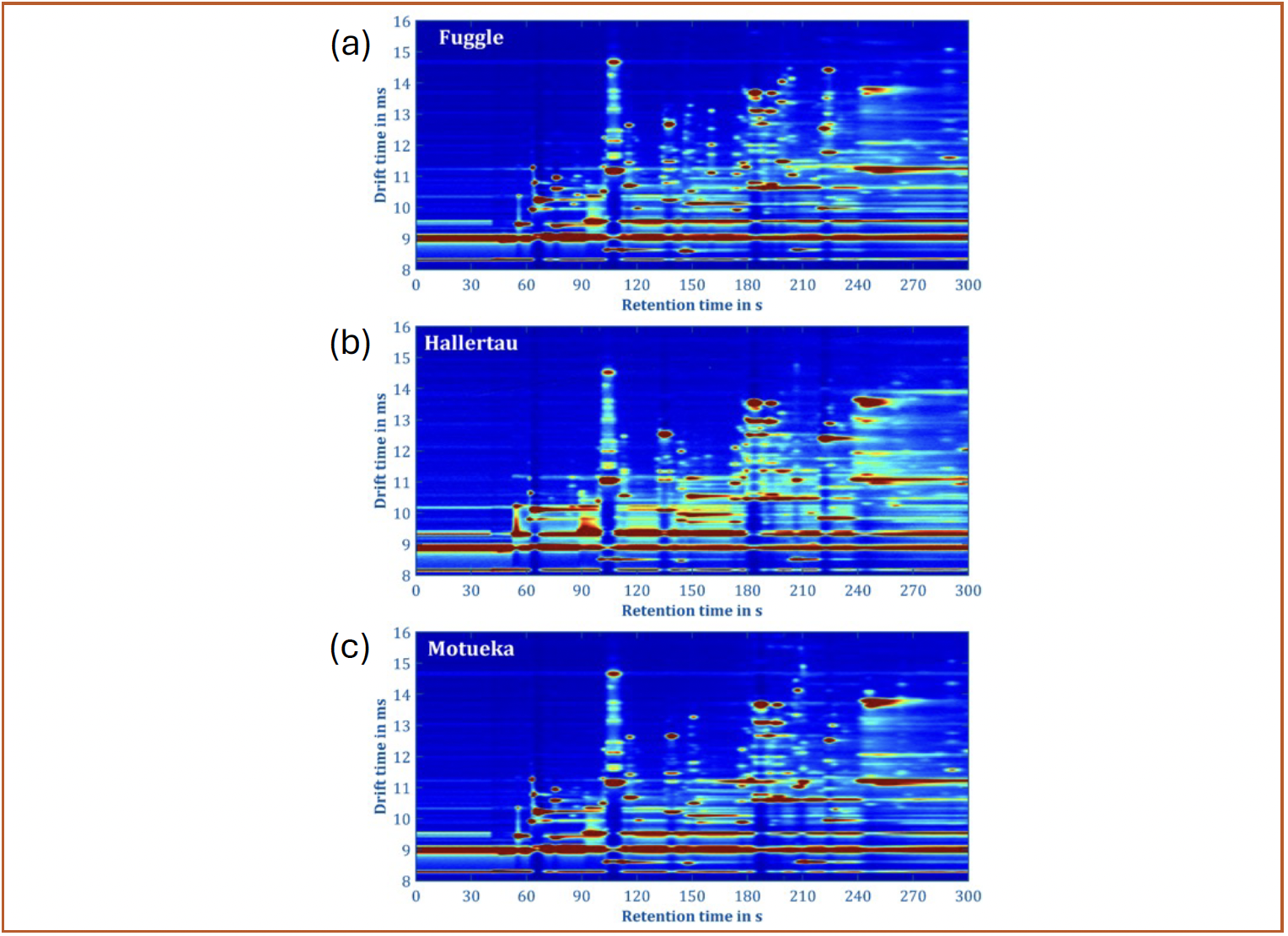
IMS can reach impressive resolving power, which is defined as the ratio between drift time and the full width at half maximum (fwhm), ranging from maybe 50 for small but sophisticated instruments to over 1000 for ultra-high-end devices (5). However, the ion mobilities of many volatile analytes fall into a rather small range of less than a factor of three, as can be seen by the y-axis in Figure 2, diminishing the separation performance. Nevertheless, the resulting peak capacities for a sub-second separation still range from 35 to 650 for different IMS (11). Combined with the advantages listed above, one might conclude that IMS should be able to analyze quite complex mixtures without any pre-separation. However, this assumption would lead to a rather unpleasant surprise, as one of the biggest strengths of IMS is also their biggest weakness—the extremely sensitive chemical ionization process in the gas phase is notoriously susceptible to matrix effects as shown in many studies (12–14). Ions tend to form clusters with water molecules, changing their reactivity based on humidity. Furthermore, ions and molecules from different analytes may react with each other. In the end, some analytes can be measured extremely well with IMS, even in mixtures, while others are extremely dependent on the background and might be completely suppressed. For example, despite naphthalene and pyrene having similar sensitivities when measured separately, in a mixture they only show similar signals at a concentration ratio of 100.000 to 1! (12)
Early IMS were designed for searching for reactive analytes, such as many chemical warfare agents or explosives (15), where this discrimination is not a problem at all, but an advantage as they stand out from the background. ”Selective” ionization is often further enforced through the use of dopants, ensuring that only the most reactive analytes are visible in the spectra (16,17). However, when facing complex mixtures containing the information (for example, when working in quality control or breath gas analysis), this will likely cause loss of relevant features in the spectra. Thus, even the highest resolving IMS cannot fully reveal the composition of a sample containing compounds not amenable for simultaneous ionization. This is the reason why IMS also need gas chromatography—the preceding separation from the GC breaks down complex samples into smaller chunks containing less components competing for ionization. In the combination of a GC-IMS, both techniques can bring their biggest strengths to bear.
Barring the initial quip regarding Lovelock’s work, the first actual GC-IMS system was reported by Karasek and various associates in the 1970s (7,18,19), as an operational mode for a GC-IMS–MS coupling. In the following decade, research on IMS drift tubes dedicated as GC detectors followed, most importantly in the works of the Hill group at Washington State University (20–22). An overview on these developments can be found in the excellent, though now slightly outdated review by Kanu and Hill from 2008 (23).
Setting Up a GC-IMS Coupling
Generally, because of the mentioned advantages, setting up a GC-IMS system is rather straightforward:
- IMS need no consumables apart from the drift gas, which can be, for example, clean air or nitrogen and may therefore already be available in many labs, for example from systems for supplying flame ionization detectors (FIDs). Because of the mentioned effects of humidity, an additional moisture trap in front of the drift gas inlet may be advisable.
- The separation principle in IMS offers good orthogonality to many different stationary phases.
- IMS drift times are fast enough to analyze all GC peaks multiple times, allowing for easy reconstruction of the peaks in GC direction. Only hyperfast GC with only a few ten millisecond peak widths (24) could prove a limitation here.
- Both standard heated transfer lines and IMS fitting directly onto detector ports have been reported as suitable solutions to avoid cold spots in the thermal design of the setup (22). The required temperature for eluting sample components with very high boiling point may be a limitation, as the complexity of an IMS makes a high temperature design more challenging, but drift tube temperatures as high as 200 °C are possible (21).
However, despite these advantages, one key challenge remains: IMS share the fate of any other GC detector with considerable interior volume, causing excessive peak broadening if not properly designed (25). Having previously developed a holistic model for predicting both the resolving power and signal-to-noise-ratio of a stand-alone IMS (26), we are currently working on extending this model to a complete GC-IMS system. The effect of the IMS on the number of theoretical plates achieved in GC dimension is of special interest here. First studies concerning these effects have been published in joint works from Kirk, Kobelt, and Kueddelsmann and colleagues (27,28), showing that the quantity of interest for the GC–MS is the ratio of the internal volume of the IMS reaction region to the internal volume of the GC column. This leads to a more or less constant number of plates across a surprisingly wide range of linear velocities in the column. Depending on the ratio between volume of the IMS and volume of the column, a significant amount of makeup gas may be necessary to prevent peak broadening. This can, even though typically not explicitly discussed, be seen in the practice of setting up GC-IMS systems.
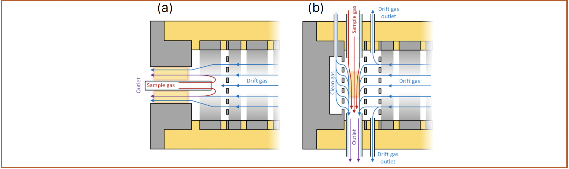
On the one hand, this ratio can be optimized through higher internal volume of the GC column. This has led to GC-IMS systems using either larger diameter columns, typically 320 μm or 530 μm, with high internal volume but also high transfer to mass resistance or using multi-capillary columns (MCC) consisting of multiple capillaries, combing even higher internal volume with low transfer to mass resistance (29). On the other hand, this ratio can be optimized through lower internal volume of the IMS reaction region. Starting from the first dedicated GC-IMS systems, this has led to specialized drift tube designs with low internal volume and optimized gas flow designs (20,21). The left hand side of Figure 3 shows an IMS with a reaction region volume of about one milliliter, unidirectional drift gas flow and direct axial sample introduction as described by St. Louis and associates (21). Here, the drift gas sweeping the reaction region acts as an additional make up gas flow already forming a laminar flow profile, while the eluent from the GC is introduced into its center. The right hand side of Figure 3 shows an IMS based on an optimized ion injection method by Kirk and colleagues (6,26), allowing to reduce the effective reaction region volume to around a hundred microliters. Combined with a focusing gas flow from one or two sides, an even faster laminar flow through the reaction region is achieved (26,30,31), allowing measuring GC peak widths of half a second (32). This could be pushed even further using miniaturized drift tubes with this flow scheme (33).

 Direct axial sample introduction utilizing the drift gas as make-up gas; and (b) focused sample introduction with a laminar flow utilizing the drift gas for focusing. The glowing rectangles mark the areas of ion generation.")
FIGURE 3: Gas flow schemes inside IMS drift tubes optimized for use as a GC detector. (a) Direct axial sample introduction utilizing the drift gas as make-up gas; and (b) focused sample introduction with a laminar flow utilizing the drift gas for focusing. The glowing rectangles mark the areas of ion generation.
Future Developments
A large part of today’s IMS research is geared towards IMS–MS systems for analysis of high mass analytes such as biomolecules. However, because of these target applications, these devices are not necessarily suitable to be used as GC detectors, where the target analytes are often lower mass. As an outlook on the possible future of GC-IMS instrumentation, we would like to present some IMS specifically geared towards chromatographic detection currently under investigation in Hanover.
First, IMS can measure both analytes with high proton affinity and analytes with high electron affinity, and, typically, a complex sample will contain both kinds of analytes. As running the same sample twice through the GC needs twice the time, it is desirable to perform both IMS measurements in a single GC run. While splitting the flow between two IMS, one measuring positive ions and the other measuring negative ions, is certainly possible, it is rather inconvenient, especially due to the issues of limited sample flow from the GC discussed previously. Thus, the preferred solution would be a single IMS able to measure both polarities simultaneously. We have realized two different dual polarity IMS concepts. On the one hand, a single reaction region can be combined with two drift tubes, meaning that when the injection pulse is applied, positive ions will be injected into one drift tube and negative ions into another, for example opposite, drift tube. Such an instrument and its coupling to a GC has been published recently by Lippmann and associates (34). On the other hand, IMS are operating on a millisecond timescale and thus significantly faster than GC as discussed before. Thus, it is possible to reverse all voltages of the IMS periodically during one GC run to record spectra in both ion polarities using a single but ultra-fast polarity switching IMS. Such an instrument and its coupling to a GC has been published recently by Hitzemann and colleagues (35).
Second, the fact that both GC and IMS can be readily miniaturized has led to a possible realization of the long dream of handheld multidimensional analysis, where the loss of performance because of miniaturization is mitigated by the orthogonal separations (36,37). A handheld GC-IMS system, though requiring an additional gas bottle, was the first to meet this definition in 1993 (38). However, no further developments on this system were reported and in the following years, no further reports on hand-held GC-IMS appeared in the literature. Recently, Ahrens and associates published a compact GC-IMS system about the size of a shoebox that combines a miniaturized drift tube with a 7 x 1 m multi capillary column (MCC) (33,39). This system can even be operated with ultrafast polarity switching to quasi simultaneously measure spectra in both ion polarities (35).
Third, IMS are, of course, not limited to being detectors for GC, but can also be used in conjunction with other chromatographic techniques such as high performance liquid chromatography (HPLC) (40,41). Here, the sample is introduced into the IMS via electrospray ionization (ESI). Using a special ion shutter to allow efficient injection of large molecules (42,43), high-performance IMS has been successfully coupled to chip-HPLC (44) or electrochromatography (45). However, further requirements such as efficient desolvation of the ions after spraying the solvent need to be kept in mind for these applications.
In the end, one can conclude that the combination of IMS and chromatography has not only been extremely successful in the past decades, but is continuing to grow through the development of better instruments. With these, old applications can be performed more efficiently and new applications become possible.
References
(1) Lovelock, J. E. A Sensitive Detector for Gas Chromatography. J. Chromatogr. A 1958, 1, 35–46. DOI: 10.1016/S0021-9673(00)93398-3
(2) Lovelock, J. E.; Lipsky, S. R. Electron Affinity Spectroscopy—A New Method for the Identification of Functional Groups in Chemical Compounds Separated by Gas Chromatography. J. Am. Chem. Soc. 1960, 82 (2), 431–433. DOI: 10.1021/ja01487a045
(3) Pellizzari, E. D. Electron Capture Detection in Gas Chromatography. J. Chromatogr. A 1974, 98 (2), 323–361. DOI: 10.1016/S0021-9673(00)92077-6
(4) Cumeras, R.; Figueras, E.; Davis, C. E.; Baumbach, J. I.; Gràcia, I. Review on Ion Mobility Spectrometry. Part 1: Current Instrumentation. Analyst 2014, 140, 1376–1390. DOI: 10.1039/c4an01100g
(5) Kirk, A. T.; Bohnhorst, A.; Raddatz, C.- R.; Allers, M.; Zimmermann, S. Ultra-High-Resolution Ion Mobility Spectrometry—Current Instrumentation, Limitations, and Future Developments. Anal. Bioanal. Chem. 2019, 411, 6229–6246. DOI: 10.1007/s00216-019-01807-0
(6) Kirk, A. T.; Küddelsmann, M. J.; Bohnhorst, A.; Lippmann, M.; Zimmermann, S. Improving Ion Mobility Spectrometer Sensitivity through the Extended Field Switching Ion Shutter. Anal. Chem. 2020, 92 (7), 4838–4847. DOI: 10.1021/acs.analchem.9b04259
(7) Cohen, M. J.; Karasek, F. W. Plasma Chromatography™—A New Dimension for Gas Chromatography and Mass Spectrometry. J. Chromatogr. Sci. 1970, 8 (6), 330–337. DOI: 10.1093/chromsci/8.6.330
(8) Karasek, F. W.; Kane, D. M. Effect of Oxygen on Response of the Electron-Capture Detector. Anal. Chem. 1973, 45 (3), 576–580. DOI: 10.1021/ac60325a016
(9) Spangler, G. E.; Lawless, P. A. Comparison Between Plasma Chromatography and Electron Capture Detector. Anal. Chem. 1980, 52 (1), 193–196. DOI: 10.1021/ac50051a046
(10) Budzyńska, E.; Grabka, M.; Kopyra, J.; et al. Ion Mobility Spectrometers and Electron Capture Detector – A Comparison of Detection Capabilities. Talanta 2019, 194, 259–265. DOI: 10.1016/j.talanta.2018.10.022
(11) Grabarics, M.; Lettow, M.; Kirk, A. T.; von Helden, G.; Causon, T. J.; Pagel, K. Plate-Height Model of Ion Mobility–Mass Spectrometry: Part 2—Peak-to-Peak Resolution and Peak Capacity. J. Sep. Sci. 2021, 44 (14), 2798–2813. DOI: 10.1002/jssc.202100201
(12) Vandiver; V. J.; Leasure, C. S.; Eiceman, G. A. Proton Affinity Equilibria for Polycyclic Aromatic Hydrocarbons at Atmospheric Pressure in Ion Mobility Spectrometry. Int. J. Mass Spectrom. Ion Processes 1985, 66 (2), 223–238. DOI: 10.1016/0168-1176(85)83012-3
(13) Puton, J.; Holopainen, S. I.; Mäkinen, M. A.; Sillanpää, M. E. T. Quantitative Response of IMS Detector for Mixtures Containing Two Active Components. Anal. Chem. 2012, 84 (21), 9131–9138. DOI: 10.1021/ac3018108
(14) Safaei, Z.; Willy, T. J.; Eiceman, G. A.; Stone, J. A.; Sillanpää, M. Quantitative Response in Ion Mobility Spectrometry with Atmospheric Pressure Chemical Ionization in Positive Polarity as a Function of Moisture and Temperature. Anal. Chim. Acta 2019, 1092, 144–150. DOI: 10.1016/j.aca.2019.09.040
(15) Eiceman, A. E. Toward the Chemical Agent Monitor: Technologies and Developments in England and the United States from 1965 to 1982. Int. J. Ion Mobility Spectrom. 2020, 23, 39–49. DOI: 10.1007/s12127-019-00256-w
(16) Eiceman, G. A.; Wang, Y.- F.; Garcia-Gonzalez, L.; Harden, C. S.; Shoff, D. B. Enhanced Selectivity in Ion Mobility Spectrometry Analysis of Complex Mixtures by Alternate Reagent Gas Chemistry. Anal. Chim. Acta 1995, 306 (1), 21–33. DOI: 10.1016/0003-2670(94)00668-C
(17) Puton, J.; Nousiainen, M.; Sillanpää, M. Ion Mobility Spectrometers with Doped Gases. Talanta 2008, 76 (5), 978–987. DOI: 10.1016/j.talanta.2008.05.031
(18) Karasek, F. W.; Keller, R. A. Gas Chromatograph/Plasma Chromatograph Interface and Its Performance in the Detection of Musk Ambrette. J. Chromatogr. Sci. 1972, 10 (10), 626–628. DOI: 10.1093/chromsci/10.10.626
(19) Karasek, F. W.; Hill Jr., H. H.; Kim, S. H.; Rokushika, S. Gas Chromatographic Detection Modes for the Plasma Chromatograph. J. Chromatogr. A 1977, 135 (2), 329–339. DOI: 10.1016/S0021-9673(00)88373-9
(20) Baim, M. A.; Hill, H. H. Tunable Selective Detection for Capillary Gas Chromatography by Ion Mobility Monitoring. Anal. Chem. 1982, 54 (1), 38–43. DOI: 10.1021/ac00238a013
(21) St. Louis, R. H.; Siems, W. F.; Hill Jr., H. H. Evaluation of Direct Axial Sample Introduction for Ion Mobility Detection After Capillary Gas Chromatography. J. Chromatogr. A 1989, 479, 221–231. DOI: 10.1016/S0021-9673(01)83338-0
(22) Simpson, G.; Klasmeier, M.; Hill, H.; Atkinson, D.; Radolovich, G.; Lopez-Avila, V.; Jones, T. L. Evaluation of Gas Chromatography Coupled with Ion Mobility Spectrometry for Monitoring Vinyl Chloride and Other Chlorinated and Aromatic Compounds in Air Samples. J. High Resolut. Chromatogr. 1996, 19 (6), 301–312. DOI: 10.1002/jhrc.1240190602
(23) Kanu, A. B.; Hill Jr., H. H. Ion Mobility Spectrometry Detection for Gas Chromatography. J. Chromatogr. A 2008, 1177 (1), 12–27. DOI: 10.1016/j.chroma.2007.10.110
(24) Boeker, P.; Leppert, J. Flow Field Thermal Gradient Gas Chromatography. Anal. Chem. 2015, 87 (17), 9033–9041. DOI: 10.1021/acs.analchem.5b02227
(25) Schmauch, L. J. Response Time and Flow Sensitivity of Detectors for Gas Chromatography. Anal. Chem. 1959, 31 (2), 225–230. DOI: 10.1021/ac60146a021
(26) Kirk, A. T. Driftzeit-Ionenmobilitätsspektrometer mit hoher analytischer Leistungsfähigkeit – Modellierung, Entwurf und Umsetzung. In Berichte aus der Sensorik und Messtechnik; Zimmermann, S., Ed.; Shaker Verlag, 2020.
(27) Kirk, A. T.; Kueddelsmann, M. J.; Zimmermann, S. An Optimized GC-IMS System with Significantly Increased Sensitivity. Poster Presentation at the International Conference on Ion Mobility Spectrometry, Calgary, Alberta, Canada, 2018, online 2022. DOI: 10.15488/11755.
(28) Kobelt, T.; Kirk, A. T.; Zimmermann, S. Extending the Golay Equation for Coupling a Gas Chromatograph to a Drift Tube IMS. Poster Presentation at the International Conference on Ion Mobility Spectrometry, Hannover, Germany, 2019.
(29) Malakhov, V. V.; Sidelnikov, V. N.; Utkin, V. A. Application of Multicapillary Tube as a Chromatographic Column. Dokl. Akad. Nauk 1993, 329 (6), 749–751.
(30) Zimmermann, S.; Kirk, A. T. Probeneinlasssystem und Probengasführung für ein Ionenmobilitätsspektrometer. DE 10 2019 125 482.5 A1, 2019. https://www.ezn.de/ezn-patent/probeneinlasssystem-und-probengasfuehrung-fuer-ein-ionenmobilitaetsspektrometer/ (accessed 2024-06-10).
(31) Kirk, A. T.; Kueddelsmann, M. J.; Zimmermann, S. Ultrasensitive Ion Source for Drift Tube Ion Mobility Spectrometers Combining Optimized Sample Gas Flow with Both Chemical Ionization and Direct Ionization. Anal. Chem. 2022, 94 (28), 9960–9969. DOI: 10.1021/acs.analchem.2c00955
(32) Kirk, A. T.; Kueddelsmann, M. J.; Zimmermann, S. Improving Ion Mobility Spectrometer Sensitivity Through an Optimized Sample Gas Flow. Poster Presentation at the International Conference on Ion Mobility Spectrometry (virtual), 2020, online 2023. DOI: 10.15488/13185
(33) Ahrens, A.; Zimmermann, S. Towards a Hand-Held, Fast, and Sensitive Gas Chromatograph–Ion Mobility Spectrometer for Detecting Volatile Compounds. Anal. Bioanal. Chem. 2021, 413, 1009–1016. DOI: 10.1007/s00216-020-03059-9
(34) Lippmann, M.; Kirk, A. T.; Hitzemann, M.; Zimmermann, S. Compact and Sensitive Dual Drift Tube Ion Mobility Spectrometer with a New Dual Field Switching Ion Shutter for Simultaneous Detection of Both Ion Polarities. Anal. Chem. 2020, 92 (17), 11834–11841. DOI: 10.1021/acs.analchem.0c02166
(35) Bohnhorst, A.; Kirk, A. T.; Zimmerman, S. Toward Compact High-Performance Ion Mobility Spectrometers: Ion Gating in Ion Mobility Spectrometry. Anal. Chem. 2021, 93 (15), 777–786. DOI: 10.1021/acs.analchem.0c04140
(36) Giddings, J. C. Concepts and Comparisons in Multidimensional Separation. J. High Resolut. Chromatogr. 1987, 10 (5), 319–323. DOI: 10.1002/jhrc.1240100517
(37) McClennen, W. H.; Meuzelaar, H. L. C.; Arnold, N. S. Field-Portable Hyphenated Instrumentation: The Birth of the Tricorder? TrAC, Trends Anal. Chem. 1994, 13 (7), 286–293. DOI: 10.1016/0165-9936(94)87066-7
(38) Snyder, A. P.; Harden, C. S.; Brittain, A. H.; Kim, M. G.; Arnold, N. S.; Meuzelaar, H. L. C. Portable Hand-Held Gas Chromatography/Ion Mobility Spectrometry Device. Anal. Chem. 1993, 65 (3), 299–306. DOI: 10.1021/ac00051a019
(39) Ahrens, A.; Hitzemann, M.; Zimmermann, S. Miniaturized High-Performance Drift Tube Ion Mobility Spectrometer. Int. J. Ion Mobility Spectrom. 2019, 22, 77–83. DOI: 10.1007/s12127-019-00248-w
(40) McMinn, D. G.; Kinzer, J. A.; Shumate, C. B.; Siems, W. F.; Hill Jr., H. H. Ion Mobility Detection Following Liquid Chromatographic Separation. J. Microcolumn Sep. 1990, 2 (4), 188–192. DOI: 10.1002/mcs.1220020406
(41) Thoben, C.; Werres, T.; Henning, I.; Simon, P. R.; Zimmermann, S.; Schmidt, T. C.; Teutenberg, T. Towards a Miniaturized On-Site Nano-High Performance Liquid Chromatography Electrospray Ionization Ion Mobility Spectrometer with Online Enrichment. Green Anal. Chem. 2022, 1, 100011. DOI: 10.1016/j.greeac.2022.100011
(42) Kirk, A. T.; Grube, D.; Kobelt, T.; Wendt, C.; Zimmermann, S. High-Resolution High Kinetic Energy Ion Mobility Spectrometer Based on a Low-Discrimination Tristate Ion Shutter. Anal. Chem. 2018, 90 (9), 5603–5611. DOI: 10.1021/acs.analchem.7b04586
(43) Thoben, C.; Raddatz, C.- R.; Lippmann, M.; Salehimogaddam, Z.; Zimmermann, S. Electrospray Ionization Ion Mobility Spectrometer with New Tristate Ion Gating for Improved Sensitivity for Compounds with Lower Ion Mobility. Talanta 2021, 233, 122579. DOI: 10.1016/j.talanta.2021.122579
(44) Piendl, S. K.; Raddatz, C.- R.; Hartner, N. T.; Thoben, C.; Warias, R.; Zimmermann, S.; Belder, D. 2D in Seconds: Coupling of Chip-HPLC with Ion Mobility Spectrometry. Anal. Chem. 2019, 91 (12), 7613–7620. DOI: 10.1021/acs.analchem.9b00302
(45) Hartner, N. T.; Raddatz, C.- R.; Thoben, C.; Piendl, S. K.; Zimmermann, S.; Belder, D. On-Line Coupling of Chip-Electrochromatography and Ion Mobility Spectrometry. Anal. Chem. 2020, 92 (22), 15129–15136. DOI: 10.1021/acs.analchem.0c03446
ABOUT THE AUTHORS
Ansgar T. Kirk is the CEO of ACKISION GmbH, in Hannover, Germany. Direct correspondence to: kirk@ackision.com
Tim Kobelt is a Research Engineer at the Institute of Electrical Engineering and Measurement Technology at Leibniz University, in Hannover, Germany.
Maximilian J. Kueddelsmann is a Research Engineer at the Institute of Electrical Engineering and Measurement Technology at Leibniz University, in Hannover, Germany.
Stefan Zimmermann is a Full Professor and the Director of the Institute of Electrical Engineering and Measurement Technology at Leibniz University, in Hannover, Germany.


.Close up image | Image Credit: © Prajakkit - stock.adobe.com")


. | Image Credit: © Joan Vadell - stock.adobe.com")
Detecting Hyper-Fast Chromatographic Peaks Using Ion Mobility Spectrometry
May 6th 2025Ion mobility spectrometers can detect trace compounds quickly, though they can face various issues with detecting certain peaks. University of Hannover scientists created a new system for resolving hyper-fast gas chromatography (GC) peaks.

Altering Capillary Gas Chromatography Systems Using Silicon Pneumatic Microvalves
May 5th 2025Many multi-column gas chromatography systems use two-position multi-port switching valves, which can suffer from delays in valve switching. Shimadzu researchers aimed to create a new sampling and switching module for these systems.


. From industry he went on to Florida State University, where he was assistant professor of both analytical and materials chemistry. Since 2011, he has been at the National Institute of Standards and Technology (NIST), where he is currently Scientific Advisor in the Chemical Sciences Division. André is the author of over 90 peer-reviewed scientific publications, lead author of the second edition of “Modern size-exclusion liquid chromatography,” editor of the book “Multiple detection in size-exclusion chromatography,” past associate editor of the Encyclopedia of Analytical Chemistry and, since 2015, editor of Chromatographia. He has received a number of awards, including the inaugural ACS-DAC Award for Young Investigators in Separation Science, and was also inaugural Professor in Residence for Preservation Research and Testing at the US Library of Congress. His interests lie principally in the area of macromolecular separations, both fundamental and applied.")

New Method Explored for the Detection of CECs in Crops Irrigated with Contaminated Water
April 30th 2025This new study presents a validated QuEChERS–LC-MS/MS method for detecting eight persistent, mobile, and toxic substances in escarole, tomatoes, and tomato leaves irrigated with contaminated water.