Fittings and Connections for Liquid Chromatography—So Many Choices!
LCGC North America
A bad connection between an LC column and the rest of the system can ruin a good separation. New technologies may improve the quality of these connections and the likelihood of establishing a good connection in the first place. Understanding the issues will help you choose the best option for you.
In my work mentoring people less experienced with liquid chromatography (LC), both in industry and academia, I find that one of the biggest challenges I face is getting people to appreciate the importance of making good fluidic connections in their LC systems. Good fluidic connections are most important for those in the flow path between the point of sample injection and the point of analyte detection, including connections to the injector, column, heat exchanger, and detector. If done well, most of these connections are "set it and forget it" situations, but connections to the column in particular will be changed monthly, weekly, or perhaps even daily depending on the work environment. A bad connection between the column and the rest of the system can literally ruin a good separation, so it is important to understand the factors that contribute to "good" connections. In the marketplace today, we observe many vendors of chromatography consumables introducing new technologies that may both improve the quality of these connections and the likelihood of establishing a good connection when one is made. As users of these technologies we are faced with many choices; understanding the issues in detail should help us make better decisions that serve us well. In this month's "LC Troubleshooting," I review the basic principles involved in making good connections, discuss what has changed over the past three decades and what has remained the same, and describe some recently introduced technologies that increase the likelihood of making good connections.
Reviewing the Basics
What follows is a short list of the characteristics of an ideal connection between components of an LC system:
- Leak-free (today, up to 20,000 psi, or more)
- No unswept volumes (also referred to as voids or dead volumes)
- No distortion of connected parts
- The connection can be broken and remade (that is, disconnected and reconnected) many times without changes in performance
- Inexpensive components
As with most things in chromatography we end up making compromises, and so it is too with fittings and connections in LC that we cannot have everything we want. I think the adage "you get what you pay for" mostly applies here in the sense that we have to pay more for fittings that consistently provide good performance and convenience. Figure 1 shows the anatomy of a typical connection in an LC system. This connection could be between a valve port or column endfitting and a connecting capillary, for example. The vast majority of consumables on the market for this purpose rely on the formation of a seal between the cone-shaped ferrule and the cone-shaped part of the receiving port. The nut drives this ferrule into the port, making leak-tight contact between the two surfaces (metal–metal, metal–polymer, or polymer–polymer). At the same time, the compression of the cone on the ferrule occurs with enough force that the ferrule effectively becomes locked into place, especially for metal ferrules.
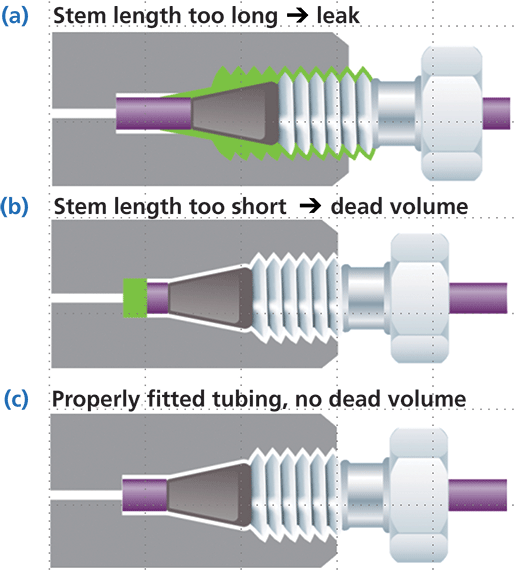
Figure 1: Anatomy of a compression-style connection of a connecting capillary to a valve port, column endfitting, pump outlet, or detector inlet: (a) stem too long, (b) stem too short, (c) properly fitted tubing. Adapted with permission from reference 1.
Figures 1a and 1b show the two most common ways that this connection process can go wrong. In the first case, if anything prevents the ferrule from moving fully into the receiving port, there is insufficient contact between the ferrule and the port surface, and the connection will leak, anywhere from a little to a lot. This situation most commonly results from using a connecting capillary that has the ferrule preswaged (that is, locked into place as a result of a connection made previously with a different receiving port) to a port depth that is different from the port depth involved in the current connection. Figure 2 shows that port depths vary by manufacturer, with differences ranging from zero to several millimeters. In the second case (Figure 1b) the ferrule is positioned too close to the end of the capillary, this time resulting in an unwanted void volume in the port. This incorrect positioning and added void volume can result again from moving a capillary with a preswaged ferrule from one port to another, or even from breaking and remaking a connection to the same port. The unwanted additional volume inevitably causes broadening of peaks observed at the detector; whether or not it results in a measurable increase in peak width or change in peak shape will depend on a number of factors including the size of the void, the inherent performance of the column (that is, how narrow the peaks are in volume units), and conditions of the experiment. This effect usually appears as additional peak tailing, and will be most pronounced for early-eluted peaks. Figure 3 shows an example of this effect, where a very long tail was observed in the case when a small void was deliberately introduced in the column connection by using an improperly positioned ferrule. The type of tailing observed in this instance can be very problematic in cases where a small peak of interest is eluted in the tail of a much larger neighboring peak, and the chromatographic resolution is compromised because of the bad connection. In my laboratory, we have made an instructional video that helps aspiring chromatographers understand the correct procedure for establishing a good connection. A few examples of such demonstrations can be found online as well (2).
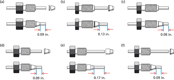
Figure 2: Ferrule shapes and port depths associated with connections to parts from different manufacturers: (a) Swagelok, (b) Waters, (c) Valco, (d) Parker, (e) Rheodyne,
Some Things Stay the Same, But . . .
The basic principles associated with good connections in LC have not changed since the days of the early high performance liquid chromatography (HPLC) systems. Indeed, the images shown in Figures 1 and 2 are very similar to the ones used by John Dolan and his coauthors in the early "LC Troubleshooting" columns he wrote in the 1980s on this topic (3,4). However, I'd like to comment specifically here on three aspects that have changed quite a bit since then.
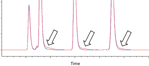
Figure 3: Comparison of chromatograms obtained with good column connections (blue) and connections with a small void introduced deliberately (red). Adapted with permission from reference 1.
Cutting Your Own Tubing
In his 1984 article (3), Dolan encouraged purchasing precut tubing, but gave advice for making good cuts in the case when you need to cut your own tubing. There was a time when I cut my own metal tubing too, but in hindsight those capillaries were awful. Given the relatively low cost of precut metal tubing today, and the potential for serious peak dispersion that could be introduced by a bad cut, it is hard to imagine justifying cutting our own tubing now. Plastic tubing, typically made of PEEK for high-pressure connections up to about 5000 psi, is a different story, however. In this case, it is relatively easy to make a good, clean, and square cut using a cutter designed for this purpose, which is available from most consumable vendors. In my laboratory, we use a lot of PEEK tubing, especially in situations where we are experimenting with different instrument configurations. After we settle on a configuration we like, then we will change all of the connections to metal capillaries because we find them to be the most reliable over time.
Interchangeability of Fittings and Multiple Connections
In a 1988 article (4), Dolan argued that the specific ferrule type did not matter much, as long as the tubing stem depth (see Figure 1) is matched to the receiving port, because the shape of the ferrule conforms to the shape of the port anyway. However, I think the bigger issue in practice is that this idea of interchangeability can quickly lead one to believe that a capillary with a swaged fitting can be moved from one port to another (for example, from a valve to a column, or from one column to another) without any problems. Today, I think moving these capillaries with preswaged fittings around is just asking for trouble. Disconnecting a capillary from a valve port and reconnecting it to the same port may work for a few times, but eventually this practice will lead to small leaks, and so it must be monitored carefully. Given the demands of modern columns for good connections to realize the full performance potential of the column, moving a preswaged capillary from one column to the next is more likely to be problematic than not. A systematic study of this issue by Stankovich, Guiochon, and coworkers clearly showed how serious this problem can be (5). They found that reusing the same preswaged fitting to connect to columns from three different manufacturers with similar endfitting designs introduced extra peak dispersion up to 7 µL2! Considering that this level of band spreading happens in the column itself in some cases, this problem with the fitting could lead to efficiency losses on the order of 50% or more. The most effective way to avoid these problems is to simply use a new capillary when making a new connection, so that the ferrule is freshly swaged and adapted to the particular receiving port involved. Of course, this approach can become expensive when making many changes to a system. In my laboratory, we carefully check for leaks when remaking connections to valves and pumps using preswaged fittings. When connecting to columns, we never use the swaged fittings shown in Figure 2; instead, we use the newer types of fittings (discussed in detail below) that are designed to be reused while making good connections each time.
Fingertight Fittings
So-called fingertight fittings are very attractive to LC practitioners simply because it is convenient to quickly make a new connection to a column or other instrument component without wrenches. Many consumables vendors advertise fingertight fittings that are leak tight up to pressures on the order of 20,000 psi without wrenches. In my laboratory, we find that some of the newer two-piece fingertight fitting designs are an improvement over older one-piece designs and are reliable up to about 10,000 psi without wrenches. Again, with this convenience comes increased costs. For very high-pressure operations up to 20,000 psi, we still find that connections are done most reliably by completing them with wrenches.
Recent Trends in Connection Technology
Two decades ago when the norm in column technology involved 5-µm particles in 150 mm × 4.6 mm columns, the column itself contributed a lot of the band spreading apparent in an observed peak, and thus the separations were relatively forgiving with respect to connections made between the components of the LC system. As column technology has improved, however, manufacturers have recognized the need to make good connections reliably, at high pressure, and repeatedly with the same capillary and endfitting. Two completely different endfitting designs that have been introduced relatively recently to address this need: the Quick Connect fitting (Agilent Technologies) and the Viper fitting (Thermo Fisher Scientific). In the first case, the fitting has an internal spring-based mechanism that ensures that the capillary stem is forced to the bottom of the receiving port as the fitting is tightened. This mechanism increases the likelihood of making a good connection every time by avoiding the type of void shown in Figure 1b. The fitting's polymer-based ferrule also conforms to slight changes in receiving port shape, allowing for reuse of the fitting many times without leaks.
The chromatograms shown in Figure 4 show that this new design can provide the same high-quality connection to the column that we expect from the swaged metal ferrule design, as we do not observe the severe peak tailing resulting from a bad connection as shown in Figure 3. Furthermore, the chromatograms show that this high-quality connection can be made many times over using the same fitting without any performance losses.
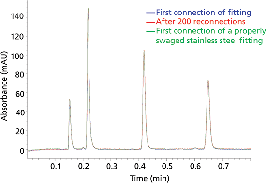
Figure 4: Comparison of chromatograms obtained with a freshly swaged stainless steel fitting (see Figure 2) and the Quick Connect fitting before and after multiple connections. Adapted with permission from reference 1.
Finally, Figure 5 shows the design of a fitting based on an approach that is completely different from the cone-shaped ferrules that have been used historically. In this case, the seal between the capillary and the receiving port is made at the very bottom of the port, increasing the likelihood that a void-free connection will be made. As with the previous design, the sealing component is polymeric, which enables the reuse of the fitting many times without performance losses. Here again these performance advantages and conveniences come at the cost of the price of the consumable part.
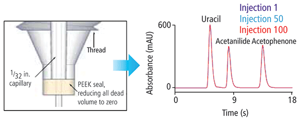
Figure 5: Design of the Viper fitting, which establishes a seal between the connecting capillary and the bottom of the receiving port rather than using a ferrule-based seal. Adapted with permission from reference 6.
Summary
LC practitioners are faced with an overwhelming number of choices for fittings that can be used to connect the components of LC systems. Users must ultimately decide which fitting technology offers the best compromise of performance and cost for each particular situation. For dedicated LC systems where system reconfiguration is infrequent-and especially for connections between instrument components excluding the column- traditional metal, ferrule-based fittings usually offer the best compromise of cost, reliability, and quality of connections. For connections to columns, particularly when changing columns frequently, reusable fittings that do not involve swaging of a metal ferrule to the capillary are very convenient. Technologies introduced by several manufacturers over the past few years have improved the design of these reusable fittings, and now enable repeated connections of high quality and at very high pressures using a single fitting. These technologies come at increased costs, but the performance gains and ease of use they provide will outweigh the costs in many practical situations.
References
(1) T. Li, D. Zeko, and M. Fuehrer, "Optimizing HPLC and UHPLC Performance with Agilent A-Line Quick Connect Fittings," presented at Analytica 2014, Shanghai, China, 2014.
(2) https://youtube/iTilOMH51Uc.
(3) J.W. Dolan and V.N. Berry, LC Magazine 2, 20–21 (1984).
(4) J.W. Dolan and P. Upchurch, LC Magazine 6, 788–790 (1988).
(5) J.J. Stankovich, F. Gritti, P.G. Stevenson, and G. Guiochon, J. Sep. Sci. 36, 2709–2717 (2013). doi:10.1002/jssc.201300175.
(6) F. Steiner, T. Piecha, T. Fehrenbach, and F. McLeod, "Ensuring Best Possible UHPLC Performance Through an Innovative Capillary and Fitting Design," presented at Pittcon 2010, Orlando, Florida, 2010.
ABOUT THE COLUMN EDITOR
Dwight R. Stoll

Dwight R. Stoll is the editor of "LC Troubleshooting." Stoll is an associate professor and co-chair of chemistry at Gustavus Adolphus College in St. Peter, Minnesota. His primary research focus is on the development of 2D-LC for both targeted and untargeted analyses. He has authored or coauthored more than 50 peer-reviewed publications and three book chapters in separation science and more than 100 conference presentations. He is also a member of LCGC's editorial advisory board. Direct correspondence to: LCGCedit@ubm.com

Troubleshooting Everywhere! An Assortment of Topics from Pittcon 2025
April 5th 2025In this installment of “LC Troubleshooting,” Dwight Stoll touches on highlights from Pittcon 2025 talks, as well as troubleshooting advice distilled from a lifetime of work in separation science by LCGC Award winner Christopher Pohl.
Mobile Phase Buffers in Liquid Chromatography: A Review of Essential Ideas
December 11th 2024In this installment of "LC Troubleshooting," Dwight Stoll discusses several essential principles related to when and why buffers are important, as well as practical factors, such as commonly used buffering agents, that are recommended for use with different types of detectors.
In-Loop Analyte Degradation in Two-Dimensional Liquid Chromatography: Example and Solutions
September 13th 2024In this installment of “LC Troubleshooting,” we describe an artifact that can arise because of compound degradation during the transfer of fractions of the first dimension (1D) column effluent to the 2D separation.


