Field-Flow Fractionation Coupled with ICP-MS for the Analysis of Engineered Nanoparticles in Environmental Samples
LCGC Europe
This article provides an overview of the capabilities of field-flow fractionation coupled with inductively coupled plasma–mass spectrometry and demonstrates that the technique shows a great deal of promise to separate, detect and quantitate nanoparticles in environmental matrices.
This article provides an overview of the capabilities of field-flow fractionation (FFF) coupled with inductively coupled plasma–mass spectrometry (ICP-MS) and demonstrates that the technique shows a great deal of promise to separate, detect and quantitate nanoparticles in environmental matrices.
The National Nanotechnology Initiative (1) defines nanotechnology as the understanding and control of materials at dimensions of 1–100 nm, where unique properties enable novel applications to be carried out. Gases, liquids and solids can exhibit unusual physical, chemical and biological properties at the nanoscale level, differing in critical ways from the properties of the bulk materials. Nanomaterials can occur in nature, such as clay minerals and humic acids; they can be incidentally produced by human activity such as diesel emissions or welding fumes; or they can be specifically engineered to exhibit unique optical, electrical, physical or chemical characteristics. Depending on their chemical and physical characteristics, these engineered nanomaterials (ENMs) can be made to exhibit greater physical strength, enhanced magnetic properties, conduction of heat or electricity, greater chemical reactivity or size-dependent optical properties.
Engineered Nanomaterials
Most ENMs can be divided into two main classes: carbonbased nanomaterials, such as nanotubes and spherical buckyballs, and metal-containing ones such as Ag, Au, Fe or TiO2 nanoparticles. Of the carbon-based ENMs, many products incorporate carbon nanotubes to improve strength. These ENMs are strongly bound to the matrix of the material and, as a result, are less likely to be released into the environment. Even though many metal-containing ENMs are also incorporated into a product matrix such as solar cells, a significant amount are used in dispersive applications. In these applications, they are intentionally released from the product, although incidental release can also be quite substantial. For example, fabrics containing silver nanoparticles used to kill bacteria release silver at varying rates during the washing cycle, depending on the type of fabric and the washing conditions. Another good example is a novel washing machine that "creates" Ag nanoparticles during the wash cycle by releasing silver nanoparticles and ions (Ag+ ) from a solid piece of Ag inside the machine.
Therefore, it is clear that the use of ENMs in consumer, industrial and agricultural products, as well as in environmental technology is growing rapidly. Often, the benefit of using nanomaterials stems from the increased surface area per unit mass of material, which increases with the inverse of the diameter. This results in faster rates of chemical reactions (for example, oxidative catalysis) occurring on material surfaces. Sometimes the benefit of nanomaterials arises from the quantum nature of energy states at the nanometer scale, as in the wavelength tuning of the fluorescence of quantum dots used in electronics applications. In the health sciences, the ability of surface-functionalized ENMs to bind to cell walls can be used for drug delivery. It has been estimated by the Project on Emerging Nanotechnologies, that there are currently more than 1000 products containing ENMs used for consumer, healthcare and industrial applications (2).
Potential for Environmental Impact
The unique properties of ENMs have also created intense interest in the environmental behaviour of these materials. Because of the increased use of nanotechnology in consumer products, industrial applications and health care technology, nanoparticles are more likely to enter the environment. Therefore, to ensure sustainable development of nanotechnology products, there is clearly a need to evaluate the risks posed by these engineered nanoparticles (ENPs), which will require proper tools to carry out exposure assessment studies. Current approaches to assess exposure include predictions based on computer modelling of ENP life cycles or, alternatively, by direct measurement techniques. Although these are very different approaches, both require instrumentation and analytical methodologies. Prediction of environmental concentrations of ENPs through modelling is based on knowledge of how they are emitted into the environment using production volumes and life cycle assessment data and also by their eventual fate and behaviour in the environment being studied (that is, soil, sediment, water and air). Although we are now starting to understand the life cycles of ENPs during production, use and disposal, there is very little known about their environmental fate and behaviour. Different ENPs will have different properties and, therefore, will behave very differently when they enter the environment.
The approach for prediction of environmental concentrations through life cycle assessment modelling requires validation through measurement of actual environmental concentrations. Extremely sensitive methods are required for ENPs that were only recently introduced into the environment. Although the direct measurement approach is not hampered by the underlying assumptions of exposure modelling, it is very important to ensure that direct observations are representative in time and space for the regional setting in which the observation was made. ENPs differ from most conventional ''dissolved'' chemicals in terms of their heterogeneous distributions in size, shape, surface charge, composition and degree of dispersion. Therefore, it is not only important to determine their concentrations, but also other metrics such as shape, size distribution and chemical composition.
Analytical Methodologies
The measurement and characterization of nanoparticles (nanometrology) is therefore critical to all aspects of nanotechnology. In the field of environmental health and safety (EHS), it has become clear that "complete" characterization of nanomaterials is critical to interpreting the results of toxicological, human health and environmental fate studies. Metal-containing ENPs form a particularly significant class, as their use in consumer products and industrial applications make them the fastest growing category of nanoparticles. Several life cycle assessments conclude that the predicted environmental concentrations (PEC) of some metal-bearing nanoparticles could exceed the predicted no effect concentration (PNEC), suggesting that ENPs can enter aquatic systems at potentially harmful concentrations. However, in most cases, these levels are typically at the part-per-trillion level.
Many analytical techniques are available for nanometrology, only some of which can be successfully applied to nano-EHS studies (3). These methods differ in part by the properties measured: average size, size distribution, surface characteristics, shape and chemical composition. Methods for assessing particle concentration and particle size distributions include electron microscopy, chromatography, centrifugation, laser-light scattering, ultrafiltration and spectroscopy. Difficulties generally arise because of a lack of sensitivity for characterizing and quantifying particles at environmentally relevant concentrations (low micrograms per litre). Furthermore, the lack of specificity of the technique is problematic for complex environmental matrices that may contain natural nanoparticles with polydisperse particle distributions, as well as heterogeneous compositions.
Electron microscopy and dynamic light scattering (DLS) are the most commonly applied methods, but they each have advantages and disadvantages. Electron microscopy gives the most direct information on the size distribution and shapes of the individual nanoparticles. However, sample preparation steps such as drying or exposure to vacuum can induce an agglomeration (clustering) of the particles, thus making it difficult to define their size in the original media. In addition, organic coatings are not visible without staining, which can lead to errors in the measurement of the particle diameter.
DLS measures the diameter of the particle while in motion (hydrodynamic diameter), and thus provides sizing of organically coated nanoparticles. Limitations of DLS include poor sensitivity at dilute concentrations, nonselective material detection, inability to distinguish mixtures in complex matrices, and difficulty in resolving the dominant size in polydisperse samples. The presence of a small number of aggregates can skew the effective diameter toward a larger particle size distribution. However, despite its limitations, DLS remains a rapid technique to quickly determine average particle hydrodynamic diameter for a wide range of particle types.
An emerging technique called single-particle inductively coupled plasma–mass spectrometry (SP-ICP–MS) has been developed for detecting and sizing metallic nanoparticles at environmentally relevant (nanograms per litre) concentrations. Although this method is still in its infancy, it has shown a great deal of promise in several applications, including determining concentrations of silver nanoparticles in complex matrices such as wastewater effluent (4). The method involves introducing nanoparticle-containing samples, at very dilute concentration, into the ICP-MS system and collecting time-resolved data. Integration times on the order of 10 ms are used to detect individual particles as pulses of ions after they are atomized by the plasma. Observed pulse number is related to the nanoparticle concentration by the nebulization efficiency and the total number of nanoparticles in the sample, and the mass, and thus the size of the nanoparticle, is related to the pulse intensity (5). However, it should be emphasized that for this approach to work effectively at low concentrations, the speed of data acquisition and the response time of the ICP-MS detector must be fast enough to capture the time-resolved nanoparticle pulses, which typically last only a few milliseconds.
Field-flow fractionation (FFF) analysis, the sizing technique highlighted in this article, is a powerful tool for sizing and separating ENPs. FFF, incorporating UV-absorbance detection, is generally limited to particle concentrations in the parts-per-million (milligramsperlitre) range and lacks particle specificity. Furthermore, UV response is not a direct measure of particle mass concentration, but rather depends on particle size, shape and optical characteristics. However, coupling FFF with a sensitive and selective multielement technique such as ICP-MS lowers detection capabilities by approximately three orders of magnitude, to the partsper-billion (microgramsper-litre) range, and provides direct information about particle mass concentration and composition (6). For this reason, it is clear that because of its elemental specificity, excellent resolution and low detection limit, ICPMS is perhaps becoming the most promising detection method for nano-EHS studies.
Field-Flow Fractionation
FFF is a single-phase chromatography technique in which separation is achieved within a very thin channel, against which a perpendicular force field is applied. One of the most common forms of FFF is asymmetrical-flow FFF, in which the field is generated by a cross-flow applied perpendicular to the channel. The flow and sample are confined within a channel that consists of two plates separated by a spacer that is typically 100–500 µm thick. The upper channel plate is impermeable and the bottom channel is made of a permeable porous frit material. A membrane covers the bottom plate to prevent the sample from penetrating the channel.
Within the flow channel, a parabolic flow profile is created because of the laminar flow of the liquid. As a result, the stream moves slowly closer to the boundary edges than it does at the centre of the channel flow. When a perpendicular force field, in this case fluid cross-flow, is applied to the flowing, laminar stream, the analytes are driven toward the boundary layer of the channel.
Diffusion, associated with Brownian motion, creates a counteracting motion. Smaller particles that have higher diffusion rates will reach an equilibrium position higher up in the channel where the longitudinal flow is faster. The smaller particles are transported much more rapidly along the channel than the larger particles, which results in the smaller particles being eluted before the larger ones.
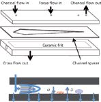
Figure 1: Separation in an asymmetrical field-flow fractionataion (FFF) channel is a result of the imposition of a parabolic channel flow velocity profile on analytes that are positioned on the channel at heights that arise from the balance of the applied field (U) and the back diffusion (D).
After a sample is injected through the inlet port of the FFF system, the flows are manipulated in such a way as to concentrate the particles into a narrow band. Following this period, the channel and cross-flows are applied to create the separation. The separated particles exit the outlet port, move into the detection system and are displayed as a temporal signal called a fractogram (similar to a chromatogram in chromatographic separation techniques). The fundamental principles of this separation process are shown in Figure 1. A typical fractogram of a mixture of silver and gold particles using UV-absorbance detection is shown in Figure 2 (7).
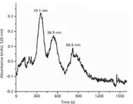
Figure 2: A fractogram of the particle size separation of a mixture of gold (Au) and silver (Ag) particles using field flow fractionation (FFF) with UV absorbance detection. Adapted from reference 7.
FFF Coupled with ICP-MS
ICP-MS has become the dominant technique for ultratracelevel quantitation of metals in environmental matrices, with multielement capabilities similar to ICPoptical emission spectroscopy (ICP-OES), and detection limits an order of magnitude lower than graphite furnace atomic absorption spectroscopy (GFAAS). This makes the technique ideal for detecting, quantifying and characterizing metal nanoparticles with extremely high sensitivity and selectivity, as well as avoiding many of the known interferences associated with complex environmental samples (8). The added benefit of using ICP-MS is that it is a rapid multielement technique, so it can be applied to the analysis of metal salt semiconductors such as cadmium selenide quantum dots. Dissolution of the cadmium selenide core is inhibited by the addition of an outer shell of zinc sulphide or similar material. ICP-MS can detect all these metals, therefore allowing the study of size-dependent dissolution or aggregation of these kinds of multielement-containing nanoparticles.
ICP-MS is also relatively straightforward to couple to FFF because the sample flow rate of the ICP-MS sample introduction system is similar to the outlet flow rate of the FFF system (~0.5–2.0 mL/min) (9). However, some challenges still have to be overcome to quantify metal concentrations in fractionated samples, as some nanoparticles tend to stick to the internal membrane of the FFF system. Figure 3 shows a typical instrumental setup for coupling an FFF system to an ICP-MS system. (Note: All the ICP-MS data published in this study were generated on an ELAN DRC II ICP-MS system from PerkinElmer, Inc.)
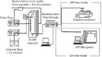
Figure 3: A typical instrumental set-up for coupling an FFF system to an ICP-MS system. The nondestructive detectors can include light-scattering, UVâvis, refractive index or fluorescence techniques.
Particle Size Reference Standards
FFF theory is well-developed for the separation and sizing of polydisperse particles in simple matrices using retention times (10). Interpreting peak areas to determine concentrations is somewhat more difficult. By using conventional detection, such as UV absorbance, refractive index, light scattering or fluorescence, the technique can use stable dispersion calibration reference standards such as NIST-traceable polystyrene beads of known particle sizes. Unfortunately, the detection of polystyrene (carbon) beads is not practical by ICP-MS. For that reason, when external size calibration is required, an in-line conventional, nondestructive detector before the ICP-MS detector is a relatively simple addition to the instrumental setup, as shown in Figure 3. As new reference materials become more available, polystyrene bead standards can be replaced with metallic nanoparticles. Currently, NIST provides monodisperse (same size and shape) gold and silver nanoparticles suitable for sizing at trace levels.
The benefit of using ICP-MS as a detection system for FFF compared to UV absorbance can be seen in Figure 4, which shows the separation of mixed gold and silver nanoparticles. It can be seen that when using UV detection alone (inset graph), the fractogram does not differentiate between the silver and gold particles and only shows the FFF separated particles by size (10, 30 and 60 nm). The main fractogram obtained using ICP-MS detection clearly shows the separated particles and the signal intensities for both the silver and gold particles at their atomic masses of 107 amu and 197 amu, respectively (7).
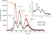
Figure 4: FFF fractogram of the separation of mixed silver and gold nanoparticles, using both UV absorbance (inset graph) and ICP-MS detection. Adapted from reference 7.
External size calibration also requires stable particle dispersions and minimal membrane interactions. For that reason, a surfactant may be needed. In some cases the surfactant most suitable for metal-containing nanoparticles may not be compatible with polystyrene standards, again suggesting that other size calibration standards would be useful. Additionally, when using ICP-MS on-line detection, other factors need to be considered with respect to choice of carrier solution. For example, the carrier solution can cause salt formation on the ICP-MS cones, leading to instability and a decrease in signal intensity over time. Another potential problem is that polyatomic spectral interferences can be created in the plasma by components in the carrier solution. For example, the use of chloride-based salts can generate interferences for elements such as vanadium, chromium, arsenic and selenium, among others. So even though modern ICP-MS instrumentation often includes a collision–reaction cell to minimize these interferences (11), the optimization of FFF separation conditions must also consider the impact on the ICP-MS system.
Calibration Strategies
In addition, the correct implementation of both internal and external calibration standards is critical in ICP-MS. Typically, internal standards are prepared in 1–5% acid and added to all calibration standards and samples. Unfortunately, the introduction of a dissolved metal standard into a near-neutral-pH FFF mobile phase can result in precipitation of analytes resulting in inaccurate metal quantification of fractionated samples. An alternative approach is to use split flows that allow the introduction of acidified internal standards directly to the ICP nebulizer after elution from the FFF channel. Internal standards have also been mixed directly into the carrier fluid and simultaneously used for external calibration by comparison of elemental response factors to the internal standard (12).
Alternative calibration approaches for FFF–ICP-MS studies include injecting a known mass of metal using a flow-injection technique and comparing the area of the known mass to the area of the unknown sample elution peak. External calibration can also be performed by analysing a continuous flow (delivered by a flow ratematched peristaltic pump) of known concentrations of metal, developing a calibration curve and then converting the intensity of the fractogram reading to a concentration value (13).
Recovery
One of the inherent limitations with quantitative applications of FFF–ICP-MS can be low recoveries, which are attributed to several factors. Probably the most significant problem area is the physical interaction of the analyte with the membrane by an adsorption mechanism, resulting in the particles sticking to the membrane and not being eluted. In addition, losses through the accumulation wall based on membrane cut-off values have been reported for samples containing dissolved and macromolecular components (13). Analyte loss can also occur in the ICP-MS nebulizer, spray chamber and sample tubing, but these losses are relatively small compared to membrane interactions.
However, when the analytical conditions are favourable, good recoveries can be achieved as demonstrated by the silver nanoparticle data shown in Figure 5. Recoveries of the three silver nanoparticle sizes tested (10 nm, 40 nm and 70 nm) at different concentrations (200 ppb, 150 ppb, 100 ppb and 50 ppb) are illustrated in the coloured bar graph, which shows the integrated ICP-MS response signal (peak area) for the FFF cross-flow field off (blue); bypassing the FFF system entirely (brown); and with the FFF cross-flow field on (green). The inset graph shows the raw fractogram data for the different concentrations of the 10-nm particles, but as can be seen by the coloured bar graphs for the 40-nm and 70-nm particles, the fractograms generated similar data. In fact, the recoveries for the four concentrations of the three different particle sizes of silver in this study were all in the range of 88–98%, based on integrated peak areas (7).
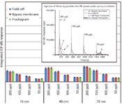
Figure 5: Comparison of recoveries of three silver nanoparticle sizes (10, 40 and 70 nm) at different concentrations (200, 150, 100 and 50 ppb), under various FFF field conditions. Adapted from reference 7.
Detection Limits
Traditional ICP-MS analysis generally has instrumental detection limits in the range of 1–100 ng/L (parts per trillion), depending on the specific element and the abundance of the isotope measured. However, in FFF applications, the mass of metal nanoparticles being detected is distributed over a size range that is diluted as the mass is spread out over the effluent volume. Spreading is a function of sample polydispersity, nonideal membrane interactions and band broadening. For this reason, the detection limit is more appropriately defined as a mass, where the mass-based detection limit (mDL) is the product of the instrument detection limit and the peak width, as shown in Figure 6(a). This example shows the uranium elution profile during the measurement of uranium bound to monodisperse hematite (Fe2O3) nanoparticles along with fractograms scaled down by factors of 2 and 10. If the area (mass) under the elution peak is compared with the area (mass) defined by the mDL, it is clear that the 0.1 scale fractogram is roughly the same area as the mDL and, as a result, the mass of uranium would be very difficult to accurately quantitate (14).
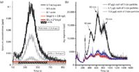
Figure 6: (a) The detection limit in FFFâICP-MS studies is defined as a mass, where the mass-based detection limit (mDL) is the product of the instrument detection limit and the peak width. Adapted from reference 14. (b) In a three-particle mixture, the effect of polydispersity degrades the detection limit. Adapted from reference 15.
In particle mixtures the effect of polydispersity is even more dramatic. Figure 6(b) shows a fractogram of a mixture of three sizes of silver nanoparticles (10, 40 and 70 nm) containing a total Ag concentration of 201 µg/L (67 µg/L each of the three sizes of particles), together with serial dilutions of five-fold (purple peaks) and 10-fold (red peaks) of the mixture. Of the diluted samples, clearly only the five-fold dilution sample (total 40.2 µg/L Ag) is far enough above the background to allow it to be quantified with good accuracy and precision. With the 10-fold dilution sample, probably only the 40-nm particles have generated a quantifiable peak, as the 6.7-µg/L (20.1 µg/L total) three-particle mixture results in a fractogram that is only slightly above the background (15).
Conclusion
This overview of the capabilities of field-flow fractionation coupled with ICP-MS has demonstrated that this hyphenated technique shows a great deal of promise to separate, detect and quantitate nanoparticles in environmental matrices. FFF is a mature separation technique that has been used for more than 35 years and, when combined with detection techniques such as UV absorbance, has proved to be very capable of separating low concentrations of polydisperse particles. The recent coupling of ICP-MS with FFF has lowered its detection capability by more than three orders of magnitude and has allowed for multielement detection, which is proving to be absolutely critical when performing environmental risk assessments studies of different engineered nanoparticles.
However, there are still challenges to overcome, both in the FFF system and in the ICP-MS system. One of the recognized problem areas is poor recoveries, which can be partly attributed to the nanoparticles sticking to the FFF membrane and not being eluted into the detection system. It is also critical to develop optimized FFF run conditions as well as external and internal ICP-MS calibration routines, which are each extremely important to achieve good accuracy, precision and recoveries of metal concentrations in fractionated samples. As more studies are published, researchers in this field will have a better understanding of how to minimize these problem areas and it is only a matter of time before FFF–ICP-MS becomes a routine analytical technique for the measurement of ENPs in environmental samples.
Robert Thomas is a consultant and science writer specializing in trace element analysis.
Ken Neubauer is a Senior Scientist with PerkinElmer, specializing in ICP-MS and LC–ICP-MS.
Denise Mitrano is in the final year of her doctoral research at the Colorado School of Mines in the Department of Chemistry and Geochemistry.
Dr. James Ranville is an associate professor in the Department of Chemistry and Geochemistry at the Colorado School of Mines. Please direct correspondence to: jranvill@mines.edu
References
(1) National Nanotechnology Initiative, www.nano.gov.
(2) Project on Emerging Nanotechnologies: www.nanotechproject.org/process/assets/files/6703/nano_researchbrief_em.pdf.
(3) M. Hassellov et al., Ecotoxocology 17, 344–361 (2008).
(4) D.M. Mitrano et al., Environ. Toxicol. Chem. 31(1), 115–121 (2012).
(5) C. Degueldre and P.Y. Favarger, Colloids and Surfaces A: Physicochem. Eng. Aspects 217, 137–142 (2003).
(6) H.E. Pace et al., Environ. Toxicol. Chem. 29, 1338–1344, (2010).
(7) E.K. Lesher et al., in Field Flow Fractionation in Biopolymer Analysis, S. Williams, R. Kim and K.D. Caldwell, Eds. (Springer, 2012), ISBN 978-3-7091-0153-7.
(8) D.J. Burleson et al., Journal of Environmental Science and Health 39, 2707–2753 (2005).
(9) R. Beckett, At. Spectrosc. 12, 228–232 (1991).
(10) J. Giddings and K. Caldwell, in Physical Methods of Chemistry, B.W. Rossiter and J.F. Hamilton, Eds. (Wiley-Interscience, New York, New York, 1989), Volume 3, part b.
(11) R.J. Thomas, Practical Guide to ICP-MS: 2nd Edition (CRC Press, Boca Raton, Florida, 2009).
(12) X. Diaz et al., Appl. Geochem. 24, 1653–1665 (2009).
(13) S. Dubascoux et al., J. Anal. At. Spectrom. 25, 613–623 (2010).
(14) E.K. Lesher et al., Environ. Sci. Technol. 43, 5403–5409 (2009).
(15) A.R. Poda et al., J. Chromatogr. 1218(27), 4219–4225 (2011).

Retaining Talent in Field-Flow Fractionation: An Initiative
The authors present their motivation for establishing the Young Scientists of FFF (YSFFF) initiative within the FFF community.
Developments in Field‑Flow Fractionation Coupled to Light Scattering
December 8th 2020Field-flow fractionation (FFF) coupled to light scattering is a powerful method to separate and characterize nanoparticles, proteins, and polymers from a few nanometres to a few micrometres. The technique is one of the few that can cover the full size range of nanomaterials and provide high-resolution size distributions and additional characterization. New developments in FFF enhance performance and productivity.
Field-Flow Fractionation: Virtual Optimization for Versatile Separation Methods
August 8th 2017Flow-field flow fractionation (flow-FFF) offers highly versatile separations for the analysis of complex fluids, covering a size range of macromolecules and particles from 1 nm to 10,000 nm. However, flow-FFF is often perceived as a difficult technique to learn because of the multiple parameters available for adjustment. Recent advances in software for simulating flow-FFF overcome this obstacle, enabling the virtual optimization of flow-FFF methods and opening up the power of flow-FFF separations to non-experts. An added benefit is the ability to easily analyze particle size distributions by elution time from first principles.


