Evolution of LC Troubleshooting: Protective Devices and Column Repair
As chromatography technologies change, our approaches to using them in ways that value reliability, as well as the ways we should approach troubleshooting and fixing problems, should also change. In this instalment, we survey several protective and troubleshooting strategies, and discuss which approaches have changed over time, and which ones have not. Understanding how the use of these approaches has evolved is helpful both for designing reliability into new methods and when considering updates to legacy methods that have been in use for decades.
In recent months, I’ve been hearing from several readers of this column that they’ve appreciated the more educational, “back-to-basics” flavour of some of the “LC Troubleshooting” instalments this past year. So, this month I’ve decided to dip a little further into that theme and provide some perspective on the evolution of various troubleshooting topics over the last few decades. My view is that this kind of perspective is particularly valuable to those who are relatively new to the field. There are some aspects of “the way we do things” that may seem peculiar on the surface, but, in fact, are very important to the reliability of high-performing liquid chromatography (LC) methods. On the other hand, some aspects of certain methods and ways of doing things are simply unnecessary in 2023 because LC technology has evolved in such ways that the old tricks aren’t needed anymore. Sometimes, implementing the old tricks with new technology—though they provide no benefit—doesn’t do any harm, but they do add cost to analyses because they take time and resources to implement. Thus, we really ought to let them go if they are not adding any value to the method. In other words, let’s be smart about the methods we deploy. If we can’t come up with a better explanation for why something about the method is the way it is, then it’s time to let it go.
Topic #1: Inline Filters, Guard Columns, Saturator Columns, and Cleanup Columns
Frequent readers of “LC Troubleshooting” know that this topic of inline filters, guard columns, and other protective devices is one of my favourites to write about. This is because I think this is an area where tremendous gains in LC system reliability and performance can be realized by following a few simple and low-cost guidelines. Figure 1 shows a flow diagram of a simple LC system, with an emphasis on the proper locations of different protective devices. Location is important—using the correct device in the wrong location will substantially, or totally, reduce the effectiveness of the device. In the following paragraphs, I will briefly review the primary function of each device and discuss how this has changed with the evolution of LC technology. Note that the discussion assumes that we are talking about reversed-phase LC separations. Similar arguments can be made for other modes of LC, but the details will be a bit different. Readers interested in learning more details about each device can refer to past articles focused more specifically on these topics.

A) Inline Filter:
Inline filters are typically located between the sample injection point and the analytical LC column. They can also be used effectively in other locations, when called for by special circumstances. The primary role of the inline filter is to trap particulate matter that would otherwise flow to the LC column and either contaminate the stationary phase, occlude the column inlet frit, or both. Typically, the through‑pore sizes of these filters are in the range of 0.2 to 2.0 μm, which means that, in principle, they will trap any particles larger than this. The major source of particulate matter in the mobile phase at this point, which can be trapped by the inline filter, is the sample injection device. Most modern injection valves turn a polymeric rotor seal against a metallic stator. In this situation, the metal wins, and small pieces of the polymeric rotor seal are shed and released into the mobile phase over time. If these are not trapped out of the mobile phase, they will accumulate at the column inlet, causing a decrease in performance (for example, tailing peaks, loss of efficiency), and, in the worst case, occlusion of the column inlet to the point where the pressure drop across the column is so high that it cannot be used any longer. At this point, the column must be replaced. Given that this is usually about a $1000 fix, one can buy and replace many inline filters and still save money (and time, as a result of better method reliability), even if it only saves the life of a single column. Readers interested in learning more about inline filters can refer to previous instalments (1). Inline filters have been recommended for several decades, and I think this is still great advice.
B) Guard Column:
Guard columns are located between the sample injector and the analytical LC column. When an inline filter is also installed, the guard column is usually installed between the inline filter and the analytical column. Also, when an inline filter is used (please do), the primary function of a guard column, which typically contains a small amount (usual lengths are 5 to 10 mm) of the same material in the analytical column, is to trap any material from the injected sample that would otherwise cause damage to the analytical column. In most cases, such damage (which may be reversible, but likely inconvenient) occurs as a result of strong adsorption of some molecules from the sample by the stationary phase that are not eluted from the column during normal operation. For example, these could be lipids or proteins from a biological sample, which, if accumulated over time from many sample injections, could change the stationary phase chemistry enough to cause significant changes in the resolution of target analytes of interest. The financial analysis here is not as simple as it is with inline filters. The cost of a guard column is typically 10–20% of the price of an analytical column, so one has to think about how many analytical columns will be saved (or how much inconvenience can be avoided) through routine use of a guard column. In my own laboratory, we don’t use guard columns very often, but that is because much of our work is with relatively clean (chemically and physically) samples. In cases where we are analyzing complex biological samples, we routinely use guard columns. This technology is several decades old, but still a great investment in situations that call for it (1).
C/D) Cleanup Trap (C: Aqueous Solvent Line; D: Mixed Solvent):
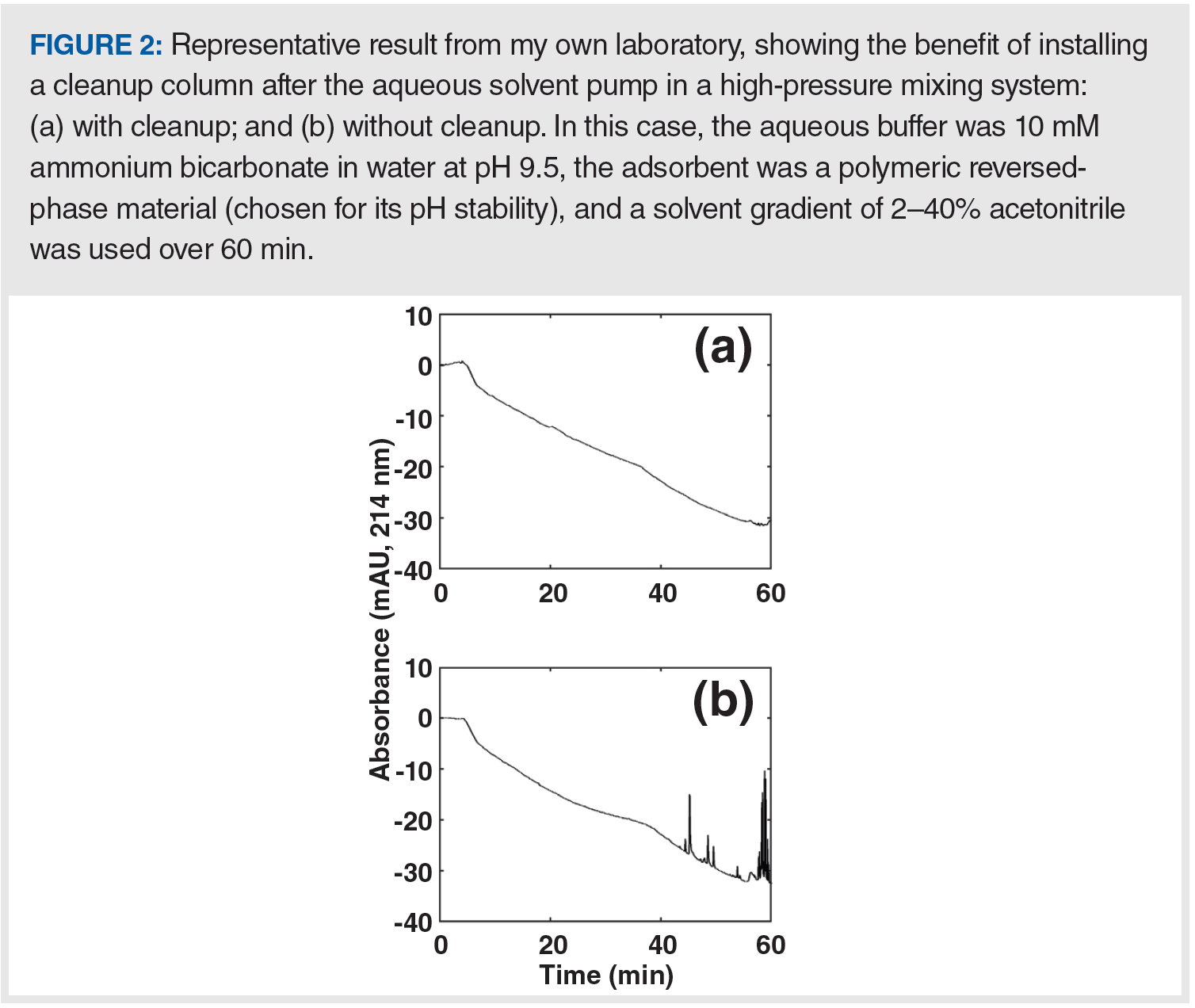
Whereas guard columns discussed in the previous section are placed after the sample injector to protect the analytical column, the same type of column can also be located between the pump and sample injector for the purpose of “cleaning up” the mobile phase (we’ll call it a trap here to differentiate the use from B, above). When a trap containing a lipophilic sorbent (for example, C18‑silica) is installed in the flow path of a mostly aqueous solvent line, prior to the point at which the mobile components are mixed, this configuration can be very effective for removing lipophilic contaminants in the aqueous solvent that would otherwise interfere with the analysis. Figure 2 shows a dramatic example of the removal of contaminants that would otherwise interfere with ultraviolet (UV) detection at 214 nm. When used in this way, the trap must be removed periodically and washed with strong solvent. It is important to note here that this approach can only be implemented with pumps based on a high pressure mixing design (see [2] for details on pump design).

Alternatively, such a trap column can also be implemented at position D in Figure 1. In this case, the mobile phase is passed through the trap after the components, which are drawn from two or more solvent bottles, have been mixed. In this implementation, the trapping efficiency is typically not as great as it is when the trap is used on the line of a single solvent; however, one advantage of placing the trap at location D is that we have the opportunity to catch contaminants from any of the solvent sources. This approach is frequently used in the analysis of polyfluoroalkyl substances (PFAS), where leaching of PFAS from instrument components into the mobile phase is a major challenge, especially in applications focused on trace analysis. Readers interested in this approach are referred to the August 2018 edition of “LC Troubleshooting”, where I described this approach in more detail (3).
The implementation of trapping columns upstream from the sample injection point is a newer development relative to the long history of the use of guard columns. This is, in part, due to the continuing quest for lower and lower detection limits. In these applications, even minor mobile phase contaminants become major interferences that stand in the way of improved detection limits, and removing them from the mobile phase stream in real time can be highly beneficial.
E) Saturator Column:
The last protective device for discussion here is a so‑called “saturator”, or “sacrificial” column, installed at location E in Figure 1. The primary function of this column, which would typically be packed with silica particles, is to saturate the mobile phase with dissolved silica. When implemented with high pH mobile phases (for example, mobile phases above pH 7), which dissolve the silica, the idea is that because the mobile phase is already saturated with dissolved silica when it reaches the analytical column, the rate of dissolution of silica particles in the second column is largely suppressed (4,5). Thus, this is where the name “sacrificial” column comes from—the silica in the saturator column is sacrificed to prevent the death of the analytical column. This is one technology that has been driven almost entirely to extinction in the practice of modern LC, largely due to the development of silica-based phases that can be used at high pH (>10) without fear for rapid dissolution of the silica. When faced with a legacy method that calls for the use of a saturator column, one should ask if this is really the best option, or if the method can be updated by leveraging contemporary column technologies.
Topic #2: Column Repair
Newcomers to LC may have never heard of the concept of “repairing” a column. For old-timers, repairing columns was simply part of the know how needed to keep a laboratory running. So, what is this about? In the early days of high performance liquid chromatography (HPLC), particle sizes on the order of 10 to 40 μm were common, and a column could be prepared by literally pouring the packing material into an empty column and settling the bed by tapping on the tube until no additional particles could be added. As the columns were not prepared under pressure, with regular use, the particle bed could settle and voids (that is, empty spaces containing only mobile phase, and no particles) could form, typically at the column inlet, which would in turn lead to peak tailing and loss of efficiency. To repair the column, one could take off the inlet endfitting, remove the inlet frit, and add some packing material to fill the void. Reassemble the inlet fitting, and voilà! Column performance was restored. Fortunately, or unfortunately, the days of this type of column repair are mostly behind us. Modern columns are prepared by packing the particles into the columns at very high pressures, and the preparation procedures are optimized to avoid settling of the bed and development of voids. Column manufacturers strongly advise against disassembling a column to try to repair it, and that is good advice. To me, vintage columns are a bit like vintage cars. One can fix most problems with a vintage car with pliers, a screwdriver, and a handful of wrenches. However, the vintage car will break down frequently, and certainly cannot be driven at 100 miles per hour. A newer car, like my 2013 hybrid, is difficult to fix without appropriate training from the manufacturer, so that could be viewed as a disadvantage. However, the hybrid car doesn’t break down very often, and is much higher‑performing than my grandfather’s Model T. Personally, I’m glad the days of column repair are behind us. We’re now used to 50 mm columns that will give us 15,000 plates out of the box, and our methods are better for it!
Summary
In this instalment of “LC Troubleshooting”, I’ve discussed some troubleshooting and protective strategies that have long histories in the LC community. Some of them, such as the use of inline filters, have not changed much over decades. Others, such as the use of saturator columns, have changed dramatically because of the introduction of new column technologies, to the point where the use of saturator columns is not recommended in the practice of modern HPLC. Understanding the history of these practices, and how they have evolved over time, is a useful facet of knowledge for aspiring LC troubleshooters.
References
(1) Stoll, D. R. Filters and Filtration in Liquid Chromatography—What to Do. LCGC Eur. 2017, 30 (2), 80–83.
(2) Stoll, D. R. Mixing and Mixers in Liquid Chromatography – Why, When, and How Much? Part I, The Pump. LCGC Eur. 2018, 31 (10), 558–563.
(3) Stoll, D. R. Contaminants Everywhere! Tips and Tricks for Reducing Background Signals When Using LC–MS. LCGC N. Am. 2018, 36 (8), 498–504.
(4) Atwood, J. G.; Schmidt, G. J.; Slavin, W. Improvements in Liquid Chromatography Column Life and Method Flexibility by Saturating the Mobile Phase with Silica. J. Chromatogr. A 1979, 171, 109–115. DOI: 10.1016/S0021-9673(01)95291-4
(5) Bidlingmeyer, B. A. Liquid Chromatography Problem Solving and Troubleshooting. J. Chromatogr. Sci. 1993, 31 (12), 533–533. DOI: 10.1093/chromsci/31.12.533
ABOUT THE COLUMN EDITOR
Dwight R. Stoll is the editor of “LC Troubleshooting”. Stoll is a professor and the co-chair of chemistry at Gustavus Adolphus College in St. Peter, Minnesota, USA. His primary research focus is on the development of 2D-LC for both targeted and untargeted analyses. He has authored or coauthored more than 75 peer-reviewed publications and four book chapters in separation science and more than 100 conference presentations. He is also a member of LCGC’s editorial advisory board. Direct correspondence to: amatheson@mjhlifesciences.com


Common Challenges in Nitrosamine Analysis: An LCGC International Peer Exchange
April 15th 2025A recent roundtable discussion featuring Aloka Srinivasan of Raaha, Mayank Bhanti of the United States Pharmacopeia (USP), and Amber Burch of Purisys discussed the challenges surrounding nitrosamine analysis in pharmaceuticals.
Extracting Estrogenic Hormones Using Rotating Disk and Modified Clays
April 14th 2025University of Caldas and University of Chile researchers extracted estrogenic hormones from wastewater samples using rotating disk sorption extraction. After extraction, the concentrated analytes were measured using liquid chromatography coupled with photodiode array detection (HPLC-PDA).


