Essentials of LC Troubleshooting, Part III: Those Peaks Don’t Look Right
Some LC troubleshooting topics never get old, because there are some problems that persist in the practice of LC, even as instrument technology improves over time. There are many ways for things to go wrong in an LC system that ultimately manifest as peak shapes that are not good. Developing a short list of the likely causes of these results can help streamline our troubleshooting experience when peak shape-related problems occur.
Writing this “LC Troubleshooting” column and thinking about topics each month is interesting in the sense that there are some topics that just never get old. Whereas in the chromatography research world certain topics or ideas become obsolete as they are displaced by newer and better ideas, in the troubleshooting world there are certain topics that have remained relevant since the very first troubleshooting article appeared in this magazine (LC Magazine at that time) in 1983 (1). Over the last few years, I’ve focused several “LC Troubleshooting” installments on contemporary trends (for example, the relatively recent advances in our understanding of the effects of pressure on retention [2]) in liquid chromatography (LC) that are affecting the way we approach our interpretation of LC results, and approach troubleshooting with modern LC instruments. With this month’s installment, I am continuing a series I started in December of 2021 (3) that is focused on some of the “bread and butter” topics of LC troubleshooting—those elements that are essential for any troubleshooter, no matter the vintage of the system we are working with. The topics at the heart of this series are highly related to LCGC’s well-known “Guide to LC Troubleshooting” wall chart (4) that hangs in many laboratories. For the third installment in this series, I’ve chosen to focus on problems related to peak shape, or perhaps peak characteristics. Incredibly, the wall chart lists 44 different potential causes of bad peak shapes! We won’t be able to consider all of these in any detail in a single article, so in this first installment on this topic, I focus on some of the problems that I see most frequently. I hope LC users young and old will find some useful tips and reminders related to this important topic.
Everything is Possible
More and more, I find myself responding to troubleshooting questions with “Everything is possible.” This response might seem like an easy out when considering observations that are hard to explain, but I find that this response is appropriate more often than not. With many possible causes of poor peak shape, it is important to keep an open mind when considering what might be the problem, and it is important to be able to prioritize the potential causes to start our troubleshooting effort, focusing on those possibilities that are most likely.
What Is to Be Expected?
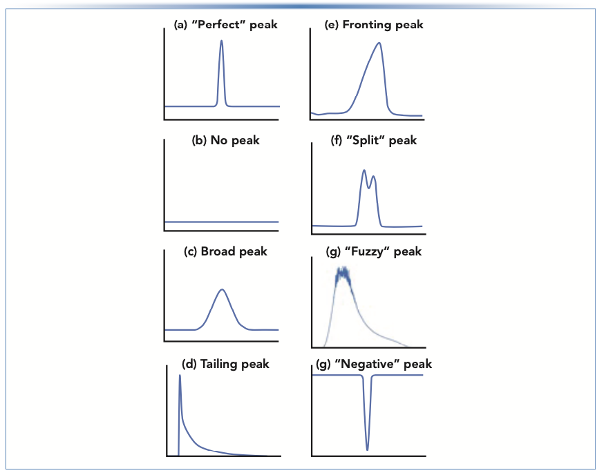
A critical step in any troubleshooting exercise—but one that I think is underappreciated—is recognizing that there is a problem to be solved. Recognizing that there is a problem usually amounts to recognizing that what is happening with the instrument is different from our expectations, which are formed from theories, empirical knowledge, and experience (5). By “peak shape,” we are really referring here to not only the shape of the peak (symmetric, asymmetric, smooth, shaggy, fronting, tailing, and so on), but also to the width. Our expectation regarding the actual peak shape is straightforward. The textbook expectation, which is well supported by theory (6), is that, under most conditions, chromatographic peaks should be symmetric and consistent with the shape of a Gaussian distribution, as shown in Figure 1a. Our expectations for the peak width is a more complicated matter, and we’ll deal with that topic in a future installment. The other peak shapes in Figure 1 show some of the other possibilities that can be observed—in other words, some of the ways that things can go wrong. In the rest of this installment, we take the time to discuss some specific examples of situations that can lead to these types of shapes.
FIGURE 1: Examples of (a) ideal, and (b–h) non-ideal peak shapes encountered in chromatography. The peaks shown in (d), (e), and (g) are from real experiments in my laboratory in the last two months.

No Peak
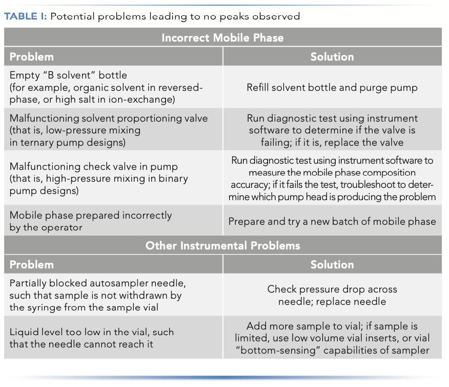
Sometimes peaks simply are not observed where they are expected to be eluted in the chromatogram. The aforementioned wall chart suggests that the absence of peaks (assuming the sample actually contains the analyte of interest at a concentration that should give a detector response sufficient to see it above the noise) is usually related to some instrumental problem, or mobile phase conditions that are incorrect (typically too “weak,” if peaks are observed at all). A short list of potential problems and solutions in this category can be found in Table I.

Too Broad
As stated above, the question of how much peak broadening one should tolerate before getting concerned and trying to troubleshoot the problem is a complex topic that I will address in a future installment. My experience has been that significant peak broadening is usually accompanied by a significant change in the peak shape, and more often peak tailing than fronting or splitting. Nevertheless, broadening of the peak that is nominally symmetrical can also occur, and could be caused by a handful of different reasons:
- “Volume overload,” where a large volume of injected sample can cause the peak to broaden (7);
- Data acquisition rate that is too slow (8);
- Connecting components of the system (for example, column and detector) with tubing that is too long or too large in diameter (9).
Each of these problems has been discussed in detail in prior installments of “LC Troubleshooting,” and readers interested in those topics are referred to those prior articles for more detail on the root causes and potential solutions to these problems.
Tailing
Peak tailing, fronting, and splitting can each be caused by chemical or physical phenomena, and the list of potential solutions for each of these problems differs greatly, depending on whether we are dealing with a chemical or physical problem. Often, an important clue about which one is the culprit can be found by comparing different peaks in a chromatogram. If all peaks in a chromatogram exhibit similar shapes, then the cause is more likely than not to have a physical origin. If only one or a couple of peaks are affected, but the rest look good, then it is more likely than not that the cause is chemical in nature.
The chemical causes of peak tailing are too complex to discuss in a short section here. Interested readers are referred to a recent installment of “LC Troubleshooting” for a more thorough discussion (10). However, one easy thing to try is to decrease the mass of analyte injected, and see if the peak shape improves. If it does, then this is a good clue that the problem is “mass overload.” In this situation, the method has to be limited to injecting less analyte mass, or the chromatographic conditions must be changed so that good peak shapes can be obtained even when injecting larger masses.
The potential physical causes of peak tailing are also numerous; readers interested in a detailed discussion of the possibilities are referred to another recent installment of “LC Troubleshooting” (11). One of the more common physical causes of peak tailing is a bad connection at some point between the sample injector and the detector (12). An extreme example of this is shown in Figure 1d, which was acquired in my laboratory a couple of weeks ago. In this case, we set up a system with a new injection valve we had not used previously, and installed a small volume injection loop that had ferrules already swaged onto the stainless steel capillary. After a few initial troubleshooting experiments, we realized that the port depth in the stator of the injection valve was much deeper than we are accustomed to, resulting in a large dead volume at the bottom of the port. This issue was easily resolved by replacing the injection loop with a different piece of tubing where we could adjust the ferrule to the proper position to eliminate the dead volume at the bottom of the port.
Fronting
Peak fronting like that shown in Figure 1e can also result from physical or chemical problems. A common physical cause of fronting is channeling in the particle bed of a column that is not well packed, or where the particles have reorganized over time. As with peak tailing, which is caused by this kind of physical phenomenon, the best solution for this problem is to replace the column and move on. Fundamentally, a fronting peak shape that has a chemical origin usually results from what we refer to as “nonlinear” retention conditions. Under ideal (linear) conditions, the amount of analyte retained by the stationary phase (and thus, the retention factor) is linearly related to the concentration of the analyte in the column. Chromatographically, this means that when the mass of analyte injected into the column is increased, the peak gets taller, but not wider. When retention behavior is nonlinear, this relationship is broken, and when more mass is injected, the peak not only gets taller, but also wider. Furthermore, the shape of the nonlinearity determines the shape of the resulting chromatographic peaks, leading to either fronting or tailing. As with mass overload that leads to peak tailing (10), peak fronting caused by nonlinear retention can also be diagnosed by reducing the mass of analyte injected. If the peak shape improves, then either the method has to be modified to not exceed the injected mass that leads to fronting, or the chromatographic conditions have to be changed to minimize this behavior.
Splitting or Shouldering
Sometimes we observe what appears to be a “split” peak, like that in Figure 1f. The first step to solving this problem is to determine whether this peak shape is due to partial coelution (that is, the presence of two different but closely eluted compounds) or not. If there are actually two different analytes eluting close together, then this is a problem of increasing their resolution (for example, by increasing selectivity, retention, or plate number), and the apparently “split” peak has nothing to do with the physical performance of the column per se. Usually, the most important clue for making this determination is whether or not all peaks in the chromatogram exhibit the splitting shapes, or just one or two. If it is just one or two, then it is probably a coelution problem; if all peaks are split, then it is probably a physical problem, most likely with the column itself.
Split peaks that are related to the physical performance of the column itself are most often because of a partially occluded inlet or outlet frit, or a reorganization of particles in the column such that channels form where mobile phase flows faster in some regions of the column than in other regions (11). A partially occluded frit can sometimes be cleared by reversing the flow through the column; however, in my experience, this is usually a short-term rather than long-term solution. If the particles have reorganized within the column, this is usually lethal with modern columns. At this point, it is best to replace the column, and move on.
“Fuzzy,” “Shaggy,” “Spiky,” or “Flat-Topped” Peaks
The peak in Figure 1g, again from a recent instance in my own laboratory, most often indicates that the signal is so high that the high end of the response range has been reached. In the case of an optical absorbance detector (UV-vis, in this case), when the analyte concentration is very high, the analyte absorbs most of the light going through the detector flow cell, leaving very little light to be detected. Under these conditions, the electrical signal from the light detector is heavily influenced by a variety of noise sources (for example, stray light and “dark currents”), such that the signal becomes very “fuzzy” in appearance, and independent of analyte concentration. When this occurs, the problem can usually be easily fixed by injecting less analyte—either by reducing the injection volume, diluting the sample, or both.
“Negative” Peaks
In chromatography school, we talk about the detector signal (that is, the y-axis in chromatograms) as an indicator of analyte concentration in the sample. Thus, it seems really weird to see a chromatogram where the signal goes below zero, as the simple interpretation would be that this indicates a negative analyte concentration—which, of course, is not physically possible. In my experience, negative peaks are most commonly observed when using optical absorbance detectors (for example, UV-vis).
In this context, a negative peak simply indicates that the molecules eluting from the column absorb less light than the mobile phase itself immediately before and after the peak. For example, this could happen when using a relatively low detection wavelength (<230 nm) and mobile phase additives that absorb a significant fraction of light at these wavelengths. Such additives could be mobile phase solvent components (such as methanol), or buffer constituents (such as acetate or formate). One can actually prepare calibration curves and obtain accurate quantitative information using negative peaks, so there is no fundamental reason to avoid them per se (this approach is sometimes referred to as “indirect UV detection) (13). However, if we really want to avoid negative peaks altogether, then the best solutions in the case of absorbance detection are to either use a different detection wavelength where the analyte absorbs more than the mobile phase, or change the constituents of the mobile phase so they absorb less light than the analyte.
Negative peaks can also occur when using refractive index (RI) detection when the components of the sample other than the analyte (for example, the solvent matrix) have a refractive index different from the refractive index of the mobile phase. This can also occur when using UV-vis detection, but the effect tends to be muted relative to RI detection. In both cases, negative peaks can be minimized by more closely matching the composition of the sample matrix to the composition of the mobile phase.
Summary
In this third installment on essential topics in LC troubleshooting, I have discussed situations where the observed peak shape is somehow different from what is expected or normal. Effective troubleshooting for this type of problem begins with a sense for what the expected peak shape is (based on theory, or prior experience with an existing method), so that a deviation from those expectations is noticeable. There are many different potential causes of peak shape problems (too broad, tailing, fronting, and so forth). In this installment, I discussed some of the causes I see most frequently in some detail. Understanding these details provides a good place to start troubleshooting, but does not capture all possibilities. Readers interested in learning about a deeper list of causes and solutions are referred to the LCGC “Guide to LC Troubleshooting” wallchart.
References
(1) D. Runser, LC Mag. 1(1), 10–16 (1983).
(2) T. Kempen and D.R. Stoll, LCGC North Am. 39(10), 471–475 (2021).
(3) D. Stoll, LCGC North Am. 39(12), 572–574 (2021).
(4) LCGC “Guide to LC Troubleshooting” Wallchart. https://www.chromatographyonline.com/view/troubleshooting-wallchart (2021).
(5) D.R. Stoll, LCGC North Am. 38(10), 505–509 (2020).
(6) A. Felinger, Data Analysis and Signal Processing in Chromatography (Elsevier, New York, NY, 1998), pp. 43–96.
(7) D.R. Stoll, LCGC North Am. 37(1), 18–23 (2019).
(8) M.F. Wahab, P.K. Dasgupta, A.F. Kadjo, and D.W. Armstrong, Anal. Chim. Acta. 907, 31–44 (2016). https://doi.org/10.1016/j.aca.2015.11.043.
(9) D.R. Stoll and K. Broeckhoven, LCGC North Am. 39(6), 252–257 (2021).
(10) D.V. McCalley and D.R. Stoll, LCGC North Am. 39(11), 526–531,539 (2021).
(11) D.R. Stoll, LCGC North Am. 39(9), 409–413 (2021).
(12) D.R. Stoll, LCGC North Am. 39(8), 353–362 (2021).
(13) M. Macka, C. Johns, P. Doble, and P. Haddad, LCGC North Am. 19(1), 38–47 (2001).
ABOUT THE COLUMN EDITOR
Dwight R. Stoll is the editor of “LC Troubleshooting.” Stoll is a professor and the co-chair of chemistry at Gustavus Adolphus College in St. Peter, Minnesota. His primary research focus is on the development of 2D-LC for both targeted and untargeted analyses. He has authored or coauthored more than 75 peer-reviewed publications and four book chapters in separation science and more than 100 conference presentations. He is also a member of LCGC’s editorial advisory board. Direct correspondence to: LCGCedit@mmhgroup.com


Polysorbate Quantification and Degradation Analysis via LC and Charged Aerosol Detection
April 9th 2025Scientists from ThermoFisher Scientific published a review article in the Journal of Chromatography A that provided an overview of HPLC analysis using charged aerosol detection can help with polysorbate quantification.
Removing Double-Stranded RNA Impurities Using Chromatography
April 8th 2025Researchers from Agency for Science, Technology and Research in Singapore recently published a review article exploring how chromatography can be used to remove double-stranded RNA impurities during mRNA therapeutics production.


