Effect of Flow Rate on UV Detection in Liquid Chromatography
LCGC North America
A deeper theoretical understanding the relationship between peak area and flow rate will help analysts diagnose problems when using UV absorbance detection.
If I increase the flow rate of my separation when using UV absorbance detection, should I expect peak area to change?
Dwight R. Stoll
In my personal experience with troubleshooting my equipment in my laboratory, and in thinking about topics for this column, I have found that effective troubleshooting skills and techniques are built on a solid foundational understanding of how the system under study (which is broken, if we are troubleshooting) is supposed to work. On a number of occasions, I have found myself thinking about and discussing with students and liquid chromatography (LC) practitioners the impact of flow rate on characteristics of chromatograms and peaks. For this month’s “LC Troubleshooting,” I’ve decided to dig into this basic, but very important, topic, with the intention that a deeper theoretical understanding of what should happen will help diagnose problems that may be related to flow rate when something does not look right.
Fundamentals
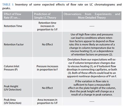
It is instructive to start a discussion of the effect of flow rate on LC separations with a kind of inventory of possible effects, along with a comparison of the predictions of simple theory and observations from real experiments (supported by more elaborate theories).
In this article, I am going to focus on the last two rows of Table I, because I have found through discussions with a variety of people that some confusion originates from these topics. Readers interested in the topics addressed in the second and third rows are referred to the references cited there for more information.

Relevant Background on Principles of Detection by Absorption of UV-Visible Light (UV Detection)
When thinking about the effects of flow rate on UV detection, it is critically important to recognize that we refer to UV detection as a type of “concentration-sensitive” detection. Concentration-sensitive detection is fundamentally different from “mass-sensitive” detection. Readers interested in the differences between these types of detection, and which LC detectors fall into which category, are referred to a recent educational article focused on this topic by Urban (4). Briefly, concentration-sensitive detectors respond to changes in analyte concentration presented to the detector (that is, moles/L, or mg/mL), whereas mass-sensitive detectors usually respond to changes in the mass of analyte presented to the detector over time (for example, pg/s). In the case of UV detection in particular, the detector reports absorbance values (A) in response to changes in analyte concentration (c) arriving at the detector. These absorbance values can be related to analyte concentration using the Beer-Lambert law:

where ε is a measure of the absorptivity of the analyte, and b is a measure of the length of the light path through the detector flow cell. Readers interested in more details associated with the inner workings of UV detectors are referred to a recent article by Dong and Wysocki in LCGC North America (5).
Details Related to the Effect of Flow Rate on Peak Height (UV Detection)
To understand the effects of flow rate on peak height and area, we need to start with a model of chromatographic peaks. In the simplest case, we use a Gaussian distribution as a model of the peak shape, which expresses the dependence of analyte concentration in the LC column effluent arriving at the UV detector on time.

Here, Cdetected,i is the concentration of the analyte arriving at the detector at time i, “moles of A” is the number of moles of the analyte injected into the column, ti is a time point in the chromatogram, tR is the retention time of the analyte, and σv and σt are the standard deviations of the distribution (that is, a measure of the peak width) in volume and time units, respectively. At the apex of a chromatographic peak, ti = tR and we have exp(0) = 1. Thus, the concentration of the analyte at the peak apex, and therefore the peak height, is entirely determined by the pre-exponential term:

Now, the moles of analyte injected are not affected by the flow rate, nor is. Although there is no explicit dependence of σv on flow rate, the flow rate will affect the peak height whenever the flow rate affects the plate height (H) of the column in use, which is almost always the case. The relationship between plate height and σv is shown in equations 4 and 5, where N is the column efficiency or plate number for the column, and VR is the retention volume of the analyte ().

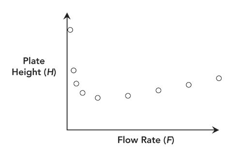
From a theoretical point of view, we know quite a bit about the dependence of plate height on flow rate through relationships such as the van Deemter equation (6). The general shape of this type of dependence is shown in Figure 1.
Figure 1: General shape of the dependence of plate height on flow rate that results from a van Deemter-type relationship .

The details of these relationships are not important here. The important fact is that, for relatively small changes in flow rate, the changes in plate height and σv, and therefore peak height, will be relatively minor, as shown by the experimental data discussed below. Readers interested in learning more about the dependence of plate height on flow rate are referred to the literature, which is a rich source of material on this topic (7).
Details Related to the Effect of Flow Rate on Peak Area (UV Detection)
Whereas the peak height is determined entirely by the pre-exponential term in equation 1, the peak area is determined by the integral of this equation, where the limits of integration are the time points that define the “start” and “end” of the peak. Indeed, when we talk about peak area, we sometimes refer to the “area under the curve.” Now, if we consider a chromatographic peak obtained with a specific set of conditions and think about what happens when we double the flow rate, we will observe that the width of the peak decreases by about a factor of two. The degree of decrease would be exactly a factor of two in a case where the plate number is not affected by flow rate, because the ratio of tR and σt is dictated by the plate number, as in equation 5. However, in most real situations, the plate number is affected by flow rate as discussed above, and the degree of change in width will be slightly different accordingly.
The net effect of flow rate on peak area in the case of UV detection is a consequence of two things happening at the same time: 1) the peak width changes in time units, expanding or contracting the integration window; and 2) the peak height is independent of flow rate, such that even if the peak becomes wider, time is added to the window over which the analyte is detected at a high concentration. In other words, the analyte flows through the UV detection cell at a finite velocity. The time over which the analyte can absorb photons is determined by the length of the light path the analyte travels through, and the velocity through that path. As the flow rate is reduced, the velocity through the detection path decreases, the residence time increases, and there are more opportunities for photons to be absorbed. Following this logic, we would expect to observe that peak area will increase in proportion to the inverse of the flow rate
that is

Let’s Look at Some Data
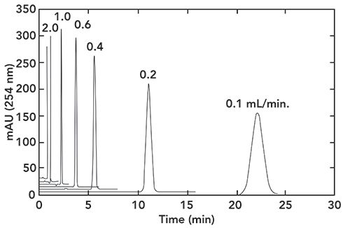
To illustrate the key points made above, I’ve made some experimental measurements of peak height and area at different flow rates, all under isocratic conditions. Figure 2 shows a series of chromatograms obtained at different flow rates in the range of 0.1 to 3.0 mL/min for the analyte acetophenone. From these chromatograms we see two clear trends: 1) the peak height varies slightly across these flow rates, but not in a simple linear way; and 2) the area under each peak obviously increases dramatically as flow rate is reduced.
Figure 2: Effect of flow rate (indicated at the top of each peak; the label for 3 mL/min is not shown for clarity). Starting from 0.1 mL/min. the baseline of each chromatogram is offset by 5 mAU to facilitate visualization. Chromatographic conditions: column, Agilent SB-C18 (50 mm x 4.6 mm i.d., 5.0-μm); mobile phase, 50:50 acetonitrile:water; temperature, 40 ÅãC; injection volume, 1 μL; data acquisition rate, 40 Hz; analyte: acetophenone at 0.5 mg/mL in acetonitrile. The retention factor of acetophenone is about 2 under these conditions.

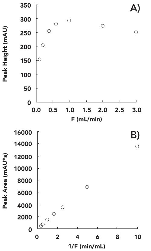
Figure 3 shows a more quantitative view of peak height (a) and area (b) results from the chromatograms shown in Figure 2. We see that the shape of the dependence of the peak height on flow rate is the inverse of the shape of the plate height versus flow rate curve shown in Figure 1. Whereas there is a minimum in the H versus F curve in Figure 1, there is a maximum in the dependence of peak height on F around 1.0 mL/min. in Figure 3a. This is expected because of the inverse relationship between Cdetected and σv.
Figure 3: Quantitative view of the dependence of peak height (a) and peak area (b) on flow rate for the separations shown in Figure 2.

On the other hand, the dependence of the peak area on flow rate (Figure 3b) is very different. We see that the peak area increases in direct proportion to the inverse of the flow rate. This is because each part of the peak moves through the detection flow cell more slowly at a lower flow rate, the residence time in the detection zone is longer, and each analyte molecule contributes more to the measured absorbance.
Closing Thoughts
Our effectiveness in troubleshooting problems with LC separations improves as we deepen our basic understanding of how the separations work. In this article, we have examined the dependence of peak height and area on flow rate when using UV detection. Whereas peak height is only weakly dependent on flow rate, the peak area is strongly dependent on F, and decreases significantly as flow rate is increased. The extent of the expected decrease is important to know when troubleshooting problems with quantitation. For example, a leak between the injector and detector could also lead to decreases in peak area at higher flow rates (and consequently higher pressures).
References
- F. Gritti, M. Martin, and G. Guiochon, Anal. Chem. 81, 3365–3384 (2009). https://doi.org/10.1021/ac802632x.
- S. Fekete, J.-L. Veuthey, D.V. McCalley, and D. Guillarme, J. Chromatogr. A 1270, 127–138 (2012). https://doi.org/10.1016/j.chroma.2012.10.056.
- J. Halvorson, A.M. Lenhoff, M. Dittmann, and D.R. Stoll, J. Chromatogr. A 1536, 185–194 (2016). https://doi.org/10.1016/j.chroma.2016.12.084.
- P.L. Urban, J. Chem. Educ. 93, 984–987 (2016). https://doi.org/10.1021/acs.jchemed.5b00986.
- M. Dong and J. Wysocki, LCGC North Am. 37, 750–759 (2019).
- J.J. van Deemter and F.J. Zuiderweg, Chem. Eng. Sci. 5, 271–289 (1956). https://doi.org/10.1016/0009-2509(56)80003-1.
- G. Desmet, Anal. Chem. 87, 8593–8602 (2015). https://doi.org/10.1021/ac504473p

Dwight R. Stoll is the editor of “LC Troubleshooting.” Stoll is a professor and co-chair of chemistry at Gustavus Adolphus College in St. Peter, Minnesota. His primary research focus is on the development of 2D-LC for both targeted and untargeted analyses. He has authored or coauthored more than 60 peer-reviewed publications and four book chapters in separation science and more than 100 conference presentations. He is also a member of LCGC’s editorial advisory board. Direct correspondence to: LCGCedit@mmhgroup.com

Polysorbate Quantification and Degradation Analysis via LC and Charged Aerosol Detection
April 9th 2025Scientists from ThermoFisher Scientific published a review article in the Journal of Chromatography A that provided an overview of HPLC analysis using charged aerosol detection can help with polysorbate quantification.
Removing Double-Stranded RNA Impurities Using Chromatography
April 8th 2025Researchers from Agency for Science, Technology and Research in Singapore recently published a review article exploring how chromatography can be used to remove double-stranded RNA impurities during mRNA therapeutics production.


