Detective Work, Part 3: Strong Retention and Chemical Problems with the Column
This is the third “LC Troubleshooting” column in a series related to problems that we associate with liquid chromatography (LC) columns. This month is the first of several discussions looking at problems that are caused by chemical problems with the column.
John W. Dolan, LC Troubleshooting Editor.
Strongly retained sample compounds can cause various changes in the appearance of a chromatogram.
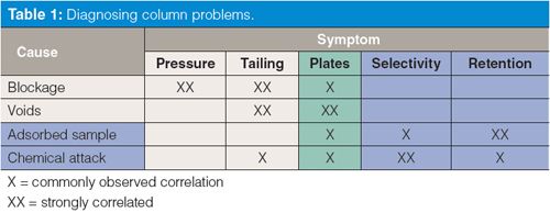
This is the third “LC Troubleshooting” column in a series related to problems that we associate with liquid chromatography (LC) columns. In part 1 (1) we looked at the major causes and symptoms associated with failure of LC columns, as summarized in Table 1. In last month’s instalment (2) we considered problems that are associated with physical problems with the column. This month is the first of several discussions looking at problems that are caused by chemical problems with the column. In Table 1, we see that chemical problems (adsorbed sample and chemical attack) are associated primarily with changes in retention and selectivity (peak spacing). This month’s topic is adsorbed samples that are strongly retained and may cause other changes in the appearance of the chromatogram.

Sample–Column Interactions
In liquid chromatography, adsorption of the sample plays a primary role in retention and separation. Consider that a sample molecule X can reside in the mobile phase, Xmp, or in the stationary phase, XC18 (assuming the stationary phase is C18). There is an equilibrium between these two conditions:
Xmp â XC18 [1]
In the normal process of retention, the equilibrium is controlled by such factors as the mobile phase organic composition, type of organic, pH, temperature, and stationary-phase characteristics. If the equilibrium is shifted to the right, retention increases; to the left, it decreases. Another analyte, Y, will have similar behaviour:
Ymp â YC18 [2]
If the two equilibria of equations 1 and 2 are sufficiently different, X and Y will be separated as they travel down the column.
With reversed-phase LC, we often assume that all the retention is because of the C18 stationary phase, but in fact this is rarely the case. Most columns have additional interaction sites, the most common of which is interaction with unbonded silanol groups, SiOH, of the silica support material. Thus, we can have some of X attracted to these sites, as well:
Xmp â XSiOH [3]
For discussion purposes, let’s consider a column with a total of 1000 interaction sites in which 20 of the sites will interact as in equation 3, and the remaining sites interact as in equation 1. Also, let’s assume that the interaction in equation 3 is so strong that for practical purposes it can be expressed as follows:
Xmp → XSiOH [4]
That is, molecules of X that interact with the silanol groups bind irreversibly. Now if we inject 100 molecules of X, 20 will be permanently bound to the silanols and the remaining 80 will be retained in the normal manner on the C18 sites. Next, make a duplicate injection and, because the silanol sites are already blocked by X bound from the previous injection, all 100 molecules of X in the second injection will be eluted. With this oversimplified model, you can see that the first injection will produce a smaller peak than the second and subsequent injections of X.
Peak Size or Retention Problems with the First Injection
It is common to observe that the first chromatogram of a run may have a different appearance from following chromatograms. This can occur with both isocratic and gradient methods. For example, the first injection might have a smaller peak area than a second, duplicate injection from the same sample vial. Or the retention time of the first injection may be a bit smaller or larger than subsequent injections. Sometimes peaks in the first injection will tail more than those of subsequent injections. This kind of behaviour is more common with large molecules, such as proteins, than small molecules with molecular weights <1000 Da; however, it can occur with all types of samples.
The most likely cause of the above observations is that some portion of the sample is strongly adsorbed on the column, as discussed above. Although it is common to think of a reversed-phase column as having primarily C18 groups bonded to a silica surface, not all of the surface of the column packing behaves the same. Some portion of the surface interacts more strongly with certain molecules than others, and this interaction is usually attributed to the unbonded silanol groups on the surface of the silica particles. Some types of silanol groups are more acidic than others and tend to interact quite strongly with basic molecules in the sample - either analytes of interest or other basic compounds in the sample matrix. With the older, type A silica columns that were the standard before 1990 and are still used with many older methods, these silanol groups were responsible for strong sample retention and peak tailing. Today’s high purity, type B columns are much less likely to cause unwanted interactions with basic compounds.
If analyte molecules are attracted to these strong retention sites, some of the injected molecules can be strongly bound to the column, while other molecules are eluted in the normal manner. However, the strong retention sites quickly become saturated, so analyte molecules in the next injection will not interact with the sites that are “blocked” by molecules from the prior injection, or if they interact, there will be no net change in the concentration adsorbed molecules. The result will be a peak that is larger in the second injection and retention times may shift a bit, too. With the type A columns, such interactions were so common that many workers added triethylamine to the mobile phase at concentrations of 25 mM or more. The triethylamine interacted more strongly with the silanol sites than the analyte molecules, effectively blocking or diminishing the unwanted interactions, especially peak tailing. Type B columns are much less likely to have such problems, so triethylamine use is much less common today. When protein samples have problems of shifting retention of peak area for the first few injections, several injections of a high concentration of protein can accelerate the equilibrium. Often, such interactions are generic enough that another protein, such as bovine serum albumin, can be loaded onto the column to deactivate it for other proteins. Triethylamine or other small molecules tend to equilibrate quickly, so the appearance of the chromatogram usually stabilizes by the second or third injection, but these materials also wash out easily during column flushing at the end of a batch of samples. Protein saturation, on the other hand, tends to be more permanent, so a single treatment may condition a column for all future uses.
This problem of reproducibility between the first and second injections is quite common. In most methods, the second and subsequent injections are stabilized relative to the first injection, so the simplest approach to solving this problem is to ignore the first injection. Just program the injection sequence so that the first sample is injected twice (or three times) and ignore the first injection.
Extra Peak in Second and Subsequent Injections

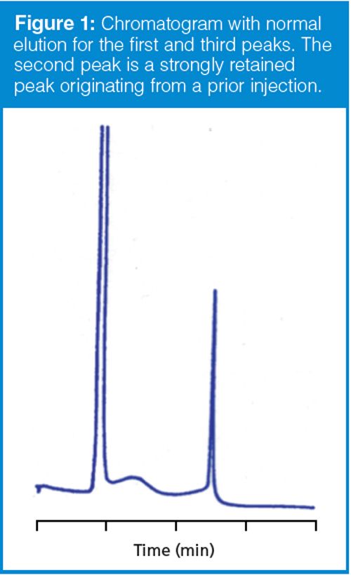
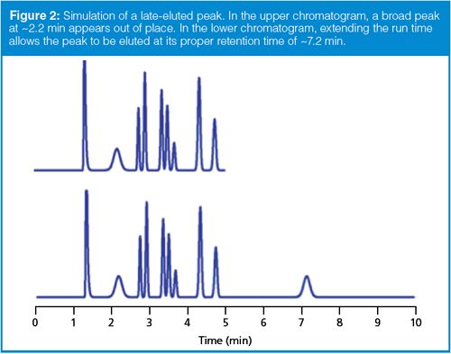
A variation on the theme discussed above is illustrated in the chromatogram shown in Figure 1. In this case, a peak appears in the chromatogram that is much broader than the neighbouring peaks. As a general rule in both isocratic and gradient separations, peaks in the same part of the chromatogram should be approximately the same peak width. In Figure 1, the first and third peak fit this description. When a broad peak appears among narrow peaks, as in Figure 1, the most likely cause is late elution. In other words, the peak doesn’t belong with the observed chromatogram; instead it is part of a prior injection, but the run time was not sufficiently long to allow it to be eluted with the proper sample. This is illustrated in the simulated chromatograms of Figure 2. In the top run of Figure 2, we see that the second peak, eluted at ~2.2 min, is broader than its neighbours. The simple way to verify that this peak is part of a previous injection is to extend the run time. In the bottom run of Figure 2, you can see that the broad peak is eluted at its normal retention time of ~7.2 min.

Usually the broad peak can be associated with the correct injection by extending the run time by a factor of two or three, as in the example of Figure 2. If this technique is not successful, you can estimate the true retention time in an isocratic method by comparing the peak widths. For isocratic runs, all the peaks in the run should have approximately the same column plate number, N:
N = 5.54 (tR/w0.5)2 [5]
where tR is the retention time of the peak and w0.5 is the peak width at half the peak height. From equation 5, you can see that the ratio of the retention time to peak width should be constant if N is constant. Thus, for two peaks (subscripts 1 and 2),
tR,2 = (tR,1 × w0.5,2)/w0.5,1 [6]
By measuring the retention and width of a normally eluted peak, plus the width of the broad peak, we should be able to estimate the true retention time of the broad peak. I did this for the broad peak of Figure 1 and came up with a retention time of 26 min! (For this chromatogram, the measurements were somewhat subjective, so I expect this estimate may be good to perhaps ±20%.) In other words, the broad peak didn’t come out from the immediately preceding injection, but from the sixth injection before the one we see in Figure 1.
There are several possible solutions to the problem of late elution, as in Figure 1 or 2. We could extend the run time of each run to allow the peak to be eluted normally. This might be practical for the method of Figure 2, but increasing the run time from 4 min to 26 min for the sample of Figure 1 wouldn’t be practical. If we were interested in the broad peak, we could use a gradient method to reduce its retention to a reasonable time. If we were not interested in the broad peak, we could flush at 4 min with a strong solvent to clear the column or perhaps adjust the run time so that the broad peak would be eluted in a region of the chromatogram where it did not interfere with peaks of interest. Another option might be to modify sample pretreatment to remove the unwanted peak before injection.
Column Flushing
In the example of Figure 1, the broad peak was still recognizable, but you can imagine that for even more strongly retained peaks and at smaller concentrations, the peaks could be so broad that they wouldn’t show up as peaks at all. Instead they would cause the baseline to wander or roll with a wavy appearance. Many real samples contain proteins, polymers, lipids, or other matrix components that are so strongly retained that by the time they are eluted, they are too broad to see. Under such conditions, the baseline will not be stable and the column chemistry may change sufficiently that the appearance of other peaks may be affected, as well. For this reason, you should flush the column after each batch of samples. Flushing with a strong solvent should remove these strongly retained materials and improve the appearance of the baseline.
Column flushing for reversed-phase columns is best accomplished using this procedure:
- Flush with buffer-free mobile phase
- Flush with 100% strong solvent
- Store or return to starting conditions
First, any buffer should be removed from the system. Usually, washing with five column volumes of unbuffered mobile phase is sufficient. (One column volume is ~1.5 mL for a 150 mm × 4.6 mm column and ~0.1 mL for a 50 mm × 2.1 mm column.) Thus, if the mobile phase were 50:50 methanol–buffer, you would flush with 50:50 methanol–water. Second, flush with 10 column volumes of 100% of the strong solvent, which is methanol in the present example. If you are finished with the column for the day, store the column in this solvent. If you want to put it back in service, return it to the original mobile phase. Remember that for column cleaning, it is the volume of solvent that is important, not the time, so you can reduce the flushing time by increasing the flow rate if the pressure is reasonable. Also, you can probably get by with using 100% water for the first flushing step, but it will often cause the column to dewet, which can require additional flushing in step two to rewet the column. (Dewetting occurs when the mobile phase, water, is so polar that it cannot enter the nonpolar pores of a reversed-phase column, so the pores are not effectively washed. Rewetting requires sufficient organic - usually 5% is sufficient - to allow the mobile phase to repenetrate the pores and wet the surface of the packing.) Finally, it should be obvious that this kind of flushing primarily applies to isocratic methods; gradient methods usually incorporate a strong-solvent flush at the end of each run.
Summary
We have seen that components of injected samples may be strongly retained and change the appearance of the chromatogram. This change may appear as shifts in retention or peak area between the first and second injections of a run sequence. In other cases, peaks may be so strongly retained that they are eluted during a following injection. Real samples often contain matrix components that are so strongly retained that if they are eluted, they result in a wavy or undulating baseline, which can compromise quantification of small peaks. Because strong retention is fairly common for many methods, it is best to ignore the first injection and to flush strongly retained materials from the column after each sample batch or run sequence.
It should be obvious that some samples will contain components that will never be washed from the column. These may build up and eventually ruin the column, or they may just alter the chemistry of the column sufficiently that chromatograms for a used column may not be identical to a new column. For this reason, it is prudent to dedicate a particular column to an individual method. That is, even if the same brand and part number of column is used for two different methods, two separate columns should be used. You will find that fewer problems will be encountered by dedicating a specific column to each method than if the same column is shared between multiple methods.
References
J.W. Dolan, LCGC Europe28(11), 612–615 (2015).
J.W. Dolan, LCGC Europe28(12), 652–656 (2015).
“LC Troubleshooting” Editor John Dolan has been writing “LC Troubleshooting” for LCGC for more than 30 years. One of the industry’s most respected professionals, John is currently the Vice President of and a principal instructor for LC Resources in Lafayette, California, USA. He is also a member of LCGC Europe’s editorial advisory board. Direct correspondence about this column should go to: “LC Troubleshooting”, LCGC Europe, Hinderton Point, Lloyd Drive, Ellesmere Port, CH65 9HQ, UK, or e-mail the editor-in-chief, Alasdair Matheson, at amatheson@advanstar.com

Quantifying Terpenes in Hydrodistilled Cannabis sativa Essential Oil with GC-MS
April 21st 2025A recent study conducted at the University of Georgia, (Athens, Georgia) presented a validated method for quantifying 18 terpenes in Cannabis sativa essential oil, extracted via hydrodistillation. The method, utilizing gas chromatography–mass spectrometry (GC–MS) with selected ion monitoring (SIM), includes using internal standards (n-tridecane and octadecane) for accurate analysis, with key validation parameters—such as specificity, accuracy, precision, and detection limits—thoroughly assessed. LCGC International spoke to Noelle Joy of the University of Georgia, corresponding author of this paper discussing the method, about its creation and benefits it offers the analytical community.


