Designing Vacuum-Jacketed User-Friendly Columns for Maximum Resolution Under Extreme UHPLC and SFC Conditions
Special Issues
Thermal effects in UHPLC and low-density SFC cause peak broadening and distortion. A solution to this problem is to thermally insulate the chromatographic column. Vacuum-jacketed column technology has been developed as a new approach to insulate the column in a practical way.
Thermal effects occurring in ultrahigh-pressure liquid chromatography (UHPLC) and low-density supercritical fluid chromatography (SFC) have a negative impact on chromatographic performance, because peaks broaden and get distorted. A solution to this problem is to thermally insulate the chromatographic column. A strict adiabatic environment can be achieved by embedding the whole chromatographic column in a large vacuum chamber, itself connected to a turbomolecular pump that delivers a high vacuum. From a practical viewpoint, this prototype research apparatus is costly, its assembly is time-consuming, and it is complex. Consequently, it is not adapted to routine analyses in standard analytical laboratories. Therefore, a new approach, using vacuum-jacketed column technology, has been developed to cope with these practical limitations. The applications and advantages of this new technology relative to standard columns are presented and discussed for both UHPLC and SFC separations operated under extreme conditions.
The high resolution power of chromatographic columns is lost when operating under extreme experimental conditions because of undesirable thermal effects. These situations occur when applying very high pressures and high flow rates, which occurs in ultrahigh-pressure liquid chromatography (UHPLC), with significant viscous heating (1), or when using low-density mobile phases at high temperature and low pressure, which occurs in supercritical fluid chromatography (SFC), with Joule-Thomson decompression cooling (2). In both cases, under a steady state temperature regime, heat is continuously exchanged between the column and its immediate external environment (3,4). As a result, temperature profiles are no longer uniform along and across the packed bed. Longitudinal temperature gradients affect essentially the retention of the analytes while radial temperature gradients negatively affect column performance in terms of efficiency and peak capacity (5,6). To get rid of the negative influence of thermal effects on the resolution power of a chromatographic column, the ideal solution consists of thermally insulating the whole body of the column. In this situation, the heat flux at the column wall would then be stopped and the amplitude of the radial temperature gradients would be reduced to zero, ensuring the most uniform flow velocity profile across the bed and maximum column performance. This solution was recently achieved by using high-vacuum technology (turbomolecular pumps) at 10-5 Torr (~1 mPa or 10-3 bar), by placing the whole column in a large (60 mm i.d.) vacuum chamber, and by covering the entire exchange surface (external and internal stainless steel walls of the column and chamber, respectively) with a thin film of aluminum (7–10).
Such an apparatus is costly, time-consuming, and complex, however, because of the need for a turbomolecular pump (to deliver air pressure as low as 10-5 Torr), an oil vacuum pump (to initiate a low vacuum), pressure gauges (to accurately control air pressure and detect air or eluent leaks), an externally controlled eluent preheater (to set the inlet temperature), a large stainless steel vacuum chamber (to insulate both column and active preheater), and a long time (overnight) to establish a steady high vacuum. As a result, even though this research apparatus delivers a perfect adiabatic environment to the column (7–10), it remains somewhat impractical for routine analyses in UHPLC and SFC.
Therefore, in this article, a new approach to this problem is discussed, involving the step-by-step development of a column hardware technology (called vacuum-jacketed column technology) that provides a strict adiabatic environment to the column. In particular, it is shown that the size of the large vacuum chamber can be significantly reduced and that a high-vacuum pump is not necessary to keep the column fully thermally insulated. Applications in UHPLC and low-density SFC are presented to illustrate the advantages of this approach under extreme operating conditions. It is also discussed how this new column technology can help users to bridge the gap between gas chromatography (GC)- and LC-like separations with a single instrument.
How to Achieve a Strict Adiabatic Environment
As mentioned above, the prototype research assembly (the solution that consists of thermally insulating the whole body of the column) consists of an oil vacuum pump (to generate a low-vacuum), a turbomolecular vacuum pump (to deliver a high-vacuum around 10-5 Torr), six pressure gauges operating in specific pressure ranges to accurately control air pressure, two pressure control readouts, two large (6 cm i.d.) stainless steel housing chambers embedding the eluent preheater and the chromatographic column, and a standard LC or SFC system. The injection valve and the inlet port of the detection cell of the chromatographic system are directly connected to the eluent preheater and to the column outlet, respectively. The strict adiabaticity of the system is controlled by accurately measuring eluent pressures and eluent temperatures at both the outlet and inlet of the column (8). The chromatographic advantage of this vacuum system is shown in Figure 1, which plots the efficiency of a 100 mm × 2.1 mm column packed with 2-µm fully porous particles as a function of the air pressure at the column surface. The pressure drop was fixed at 13,000 psi, the eluent is a mixture of acetonitrile and water (70:30, v/v) and six small molecules (uracil and 5 n-alkanophenones) were injected at room temperature. From atmospheric pressure (760 Torr) down to 10-5 Torr, a relative gain in column efficiency of ~35% is observed, which remains the same irrespective of the retention factor of the analyte (from –0.29 for uracil to 2.64 for n-hexanophenone). An air pressure level of 10-4 Torr is required for a 6 cm i.d. housing chamber. It is noteworthy that efficiency levels off between 10-1 and 102 Torr because, for such pressures, the mean free path of air molecules is always negligible with respect to the distance separating the column and the inner wall of the housing chamber. As a result, the thermal conductivity of air remain unchanged (0.03 W/m/K) regardless of the applied air pressure between 10-1 and 102 Torr. The overall efficiency gain is directly explained by the elimination of heat transport through air (heat is mostly carried by natural air convection and diffusion; a smaller portion of heat transport results from electromagnetic radiation) leading to more uniform temperature and flow velocity profiles across the packed bed than those experienced under standard conditions (7). In other words, long-range eddy dispersion in the column is minimized by keeping the temperature profile uniform across the column inner diameter. Maximum column performance is then guaranteed even under extreme operating conditions that cause undesirable thermal effects.
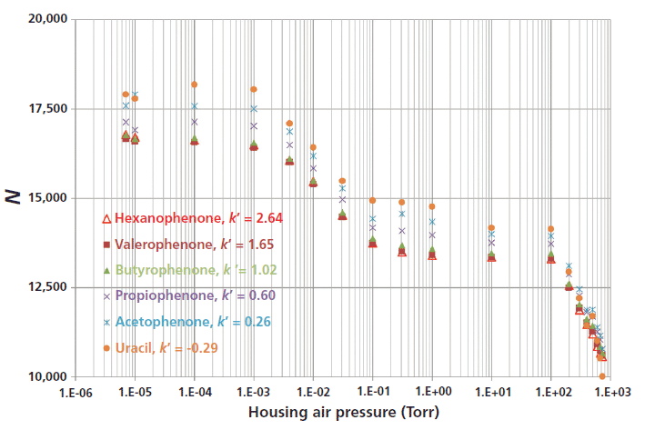
Figure 1: Illustration of the impact on column efficiency N of air pressure (decreasing from right to left from 1 atm down to 10-5 Torr) applied around a 100 mm × 2.1 mm column packed with 1.8-µm HSS-C18 particles using a research prototype LC system. Mobile phase: 70:30 (v/v) acetonitrile–water; flow rate: 0.7 mL/min; pressure drop: 13,000 psi; temperature: ambient (room) Note the average 40% relative increase in column efficiency for all the compounds irrespective of their retention factor (from –0.29 to 2.64), revealing a more uniform flow profile across the column diameter relative to standard columns.
Designing Column Hardware to Deliver a Strict Adiabatic Environment
The advantage of the research device described above is to provide a strict adiabatic environment for the column. However, such a device is highly impractical for routine analyses because of its cost, complexity, and excessive time required (about a full day) to prepare the complete system and to establish a steady high-vacuum (10-5 Torr) in the large volume housing chambers. Instead, vacuum-jacketed columns may be an alternative.
To prepare vacuum-jacketed columns, the first development step is to reduce the size of the 60-mm i.d. housing chamber (see top picture in Figure 2, labeled with orange text) that systematically delivers 100% of the maximum column performance. The middle picture in Figure 2 (prototype device phase 1, labeled with blue text) shows the same column as in the top picture but partially embedded (the inlet and outlet metal endfittings are somewhat exposed to the still air of the laboratory) in a narrower (12 mm i.d.) stainless steel tee tube. The distance between the column wall and the cylindrical chamber is then decreased from 27 mm to only 3 mm, eliminating heat transport by natural air convection. However, the column efficiency measured after decreasing the air pressure from 1 atm to 10-5 Torr is only 86% of the maximum column efficiency measured when the column is fully embedded in the large vacuum chamber. It is obvious that the hot outlet metal column endfitting is steadily exchanging heat with the external environment regardless of the air pressure in the narrow vacuum tee. Evidently, the phase 2 vacuum-jacketed column is not operating under strict adiabatic conditions.
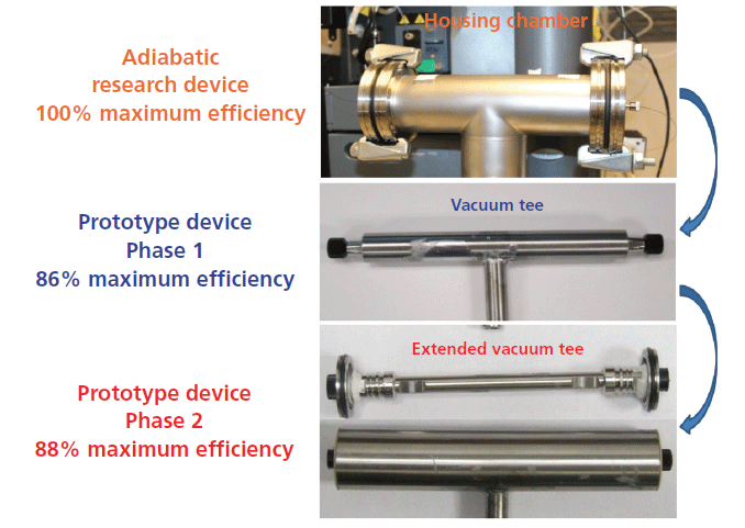
Figure 2: Development of vacuum-jacketed columns after reducing the size of the stainless steel housing chamber embedding the chromatographic column. Top: large i.d. (60 mm) housing chamber. Middle: small i.d. (12 mm) vacuum tee. Bottom: extension of the small i.d. vacuum tee to the very end of the column. Note that strict adiabatic conditions (100% maximum efficiency) are not fully achieved with the small i.d. vacuum tees; only 86% and 88% of the maximum expected efficiency, is achieved, respectively.
Therefore, a new phase 2 prototype device was designed. It is shown in the bottom picture of Figure 2 (labeled with red text). In comparison to the phase 1 prototype device, both column endfittings are now fully embedded in the cylindrical housing chamber by placing two side flanges at the very ends of the column. Surprisingly, the column efficiency measured at an air pressure of 10-5 Torr (adiabatic conditions) does not increase much with respect to that observed for phase 1 device (88% versus 86% of the maximum column performance). Heat is still circulating from the hot, bulky, metal outlet endfitting to the metal side flanges (by metal-to-metal contact and heat diffusion) and from the side flanges to the external environment (by natural laboratory air convection). The side flanges act as an undesirable heat sink and, again, the column is not operating under strict adiabatic conditions. Therefore, a phase 3 prototype device was designed, as shown in the middle picture of Figure 3 (labeled in dark green text). Two significant modifications relative to the phase 2 prototype device have been made. First, most of the metallic mass of the column endfittings has been removed (it was grinded off by a hard rotating axis) to minimize the thermal mass of the column ends. Second, the metallic flanges were replaced with two polyether ether ketone (PEEK) side flanges, which act as thermal barriers between the metal endfittings and the external environment. Eventually, under high-vacuum conditions (10-5 Torr), the measured efficiency of the column embedded in the phase 3 prototype device exactly matches the maximum efficiency expected. The key points toward the fabrication of vacuum-jacketed columns is then to ensure that the volume of the outlet metal endfitting is reduced while maintaining mechanical stability for the packed column, and that the residual heat transferred from the small metal endfitting to the external environment is reduced to zero (as a result of the insulating PEEK flanges).
The second most relevant step toward the realization of vacuum-jacketed columns is to permanently remove the low- and high-vacuum pumps used to reduce air pressure down to 10-5 Torr. This task was eventually achieved but, for the sake of intellectual property protection, the techniques and the description of the final vacuum-jacketed column are not released in this article. However, the resulting chromatographic properties are reported in the application sections below. The bottom picture in Figure 3 simply compares the experimental temperature profiles observed with an infrared camera along the external surface area of the standard and vacuum-jacketed columns. These data confirm that heat cannot be exchanged with the external environment along the entire length of the vacuum-jacketed column, thus ensuring complete thermal insulation of the packed bed.
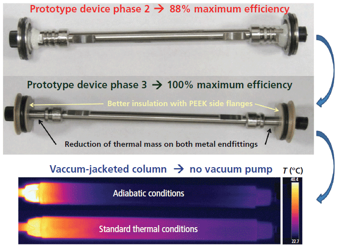
Figure 3: Development of vacuum-jacketed columns after delivering strict adiabatic conditions (100% maximum efficiency) and discarding the turbo-molecular pump. Top: partial thermal insulation of the column in a small i.d. vacuum tee extended to the very end of the column. Middle: full thermal insulation of the column placed in the small i.d. vacuum tee after reducing the endfitting mass and replacing the metal side flanges with PEEK side flanges. Bottom: picture taken with an infrared camera of the fully thermally insulated column in the absence of a high-vacuum pump. Comparison to the same type of column without thermal insulation.
UHPLC Applications
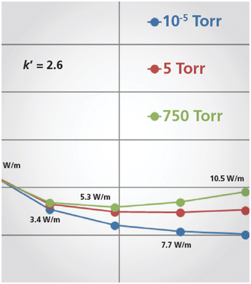
The advantage of vacuum-jacketed columns in UHPLC is first illustrated in Figure 4. The figure shows the impact of the applied air pressure surrounding the external surface area of the column on the experimental van Deemter curves of a small molecule (n-hexanophenone). When vacuum-jacketed columns are used (10-5 Torr, blue line), a reduced plate height of only 2.0 can be observed even under extreme conditions of viscous heating (13,000 psi pressure drop, 0.7 mL/min flow rate or 10.5 W/m). In contrast, a reduced plate height as large as 2.9 is actually observed when standard columns are used (750 Torr or atmospheric pressure, green line). Remarkably, the true minimum reduced plate height is expected to be smaller than 2.0 in the absence of radial temperature gradients at a reduced velocity larger than 12 (the minimum reduced plate height is just 2.6 with standard columns at a reduced velocity of 8). Thus, the apparent C term observed in separations conducted on standard columns has nothing to do with slow solid–liquid mass transfer resistance: It is fully explained by the large trans-column heterogeneity of the flow velocity (eddy dispersion, the A term) caused by the existence of a nonuniform temperature profile across the column when operating under extreme UHPLC conditions. Obviously, at the lowest applied flow rates or when viscous heating power is smaller than about a few watts per meter, the observed reduced plate height remains the same whether vacuum-jacketed or standard columns are used.
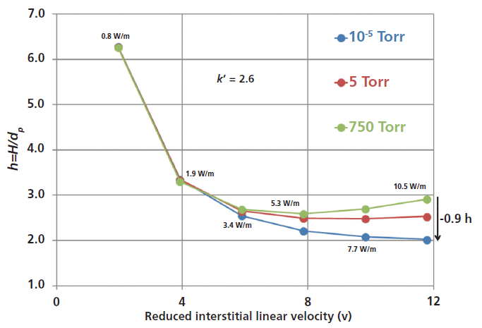
Figure 4: Effect of air pressure (750 Torr, 5 Torr, and 10-5 Torr or adiabatic conditions) applied around a chromatographic column on the van Deemter plot of a small analyte (n-hexanophenone). Column: 100 mm × 2.1 mm, 1.8-µm fully porous HSS-C18 particles; mobile phase: 70:30 (v/v) acetonitrile-water; temperature: ambient (room); flow rate: 0.1, 0.2, 0.3, 0.4, 0.5, and 0.6 mL/min. Note the increasing reduction in reduced plate height, h, with increasing flow rate and thermal effects.
The left graph in Figure 5 demonstrates that vacuum-jacketed columns significantly improve gradient performance relative to that of standard columns. The observed gain in peak capacity is close to +20% at 1 mL/min and 13,000 psi pressure drop. Similarly to what occurs under isocratic conditions, the higher the applied flow rate is, the larger the relative gain in gradient peak capacity, as it increases from +10% (0.3 mL/min) to +15% (0.65 mL/min) and to +20% (0.95 mL/min). The right graph in Figure 5 illustrates this result by looking directly at the gradient peak width: At 0.95 mL/min, the half-height peak width of a selected compound eluted at 7.5 min decreases from 1.10 s to 0.8 s when reducing the pressure from 760 to 10-5 Torr. This result confirms the gain observed for the peak capacity.
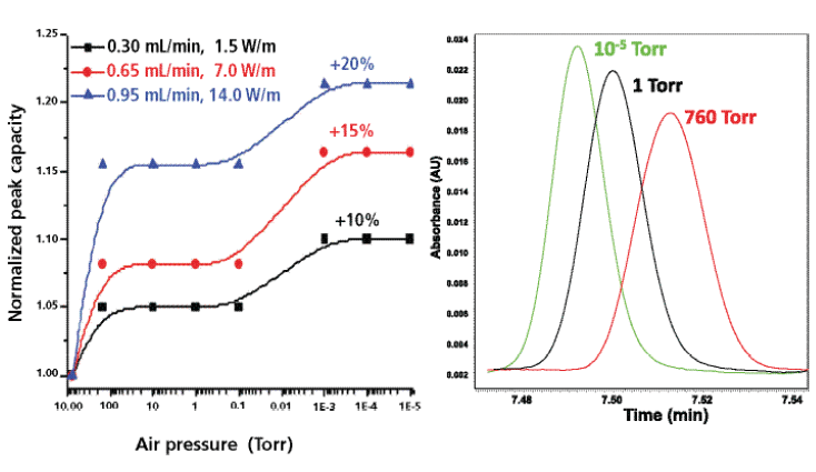
Figure 5: Left: Effect of air pressure (from 1 atm down to 10-5 Torr or adiabatic conditions) applied around a chromatographic column on the gradient peak capacity measured for three different flow rates (0.30, 0.65, and 0.95 mL/min). Sample: peptides from enolase digest. Column: 100 mm × 3.0 mm packed with 1.7 µm BEH-C18 particles; gradient: 5–40% acetonitrile in water (0.1% trifluoroacetic acid). The ratio of the gradient time to the hold-up time is kept constant at 15 for all flow rates. Right: Effect of air pressure (760 Torr, 1 Torr, and 10-5 Torr or strict adiabatic conditions) on the peak width of a selected peptide (retention time 7.5 min) at the highest flow rate of 0.95 mL/min. Note the decrease in peak width with decreasing air pressure.
SFC Applications
Figure 6 compares the SFC chromatograms of 12 light alkanes recorded with a standard (top) and a vacuum-jacketed (bottom) chromatographic column under the same extreme operating conditions (pure carbon dioxide, 1500 psi outlet pressure, 105 °C) leading to severe eluent cooling during its decompression along the column and to a dramatic loss in chromatographic performance. It is noteworthy that the peak shapes of the most strongly retained compounds are severely distorted while the resolution of the most volatile C5–C8 compounds is incomplete for standard columns. In contrast, when the newly designed vacuum-jacketed column is used, the peaks of the most strongly retained alkanes return to quasi-Gaussian shapes and baseline resolution of the most volatile compounds is achieved. Figure 7 shows another practical application, the separation of volatile terpenes (present in medicinal herbs), which requires very challenging SFC conditions (pure carbon dioxide, 1500 psi outlet pressure, 90 °C inlet temperature) to generate sufficient retention: The peak shape of the two most-retained terpenes (α-humulene and β-caryophylene) is clearly improved and the unknown impurity that is eluted between them can now be fully resolved when using the vacuum-jacketed column. Finally, Figure 8 demonstrates that vacuum-jacketed columns can be advantageous for the simultaneous separation of very volatile (C5–C8, present in gasoline) and non-volatile (C21–C36, in paraffin) n-alkanes. It is then no longer necessary to use two distinct systems to separate both volatile and nonvolatile components (a GC system to analyze the volatile fraction, and an LC system for the analysis of the nonvolatile fraction). Extreme operating conditions (pure carbon dioxide, 90 °C, and 1500 psi outlet pressure) leading to undesirable thermal effects are first required to resolve the most volatile compounds. Then, a transition from these extreme temperature-pressure conditions to less-problematic SFC conditions (higher pressure and higher content of organic modifier) is programmed: A smooth outlet pressure gradient is applied from 1500 psi to 3500 psi in 5 min to elute the heaviest compounds up to C36. Similarly, a gradient of the organic modifier content can be programmed to elute the heaviest compounds. The resolution of both the volatile and nonvolatile fractions is improved when using vacuum-jacketed columns relative to standard columns. The use of such columns makes it possible to bridge the gap between GC and LC analyses by transitioning smoothly from low-density SFC to usual SFC conditions.
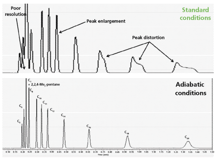
Figure 6: Isobaric separation of volatile n-alkanes (from C5 to C20) and 2,2,4-trimethylpentane under extreme operating conditions. Column: 150 mm × 3.0 mm packed with 1.8-µm fully porous HSS-SB-C18 particles; mobile phase: pure carbon dioxide; flow rate: 3.0 mL/min; column outlet pressure: 1500 psi; inlet eluent temperature: 105 °C; detection: flame ionization; injection volume: 0.2 µL. Top: standard column. Bottom: Same column type, but with vacuum-jacketing. Note the higher resolution power for the vacuum-jacketed column.
Conclusion
This work has demonstrated that the undesirable thermal effects of extreme UHPLC and SFC operating conditions can be circumvented by placing the chromatographic column in a strict adiabatic environment. A vacuum-jacketed column technology has been developed to thermally insulate the packed bed and to maintain temperature and flow velocity profiles as uniform as possible across the column diameter. This approach ensures maximum column performance regardless of the experimental conditions. The vacuum-jacketed column can be installed on any LC or SFC system without the need for a high-vacuum turbomolecular pump or large vacuum housing chambers. It is advantageously used when specifically operating under extreme experimental conditions, such as with high-speed UHPLC gradients at pressures as high as 1 kbar for faster resolution of peptide mixtures (protein digests) and low-density SFC separations of very volatile compounds traditionally analyzed by GC. This approach also opens new opportunities to bridge the gap between GC- and LC-like analyses. Low-density SFC conditions (safely applied for the analysis of volatile compounds) can be smoothly returned to usual SFC conditions (based on smooth gradients of either outlet pressure or organic modifier content), and this approach enables the analysis of both volatile and nonvolatile fractions present in the same sample mixture in a single run.
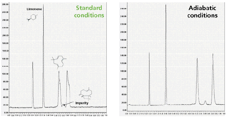
Figure 7: Isobaric separation of three volatile terpenes extracted from recreational herbs (limonene, α-humulene, and β-caryophyllene). The sample was dissolved in carbon disulfide (nearly flame ionization detection transparent). The same extreme experimental conditions as in Figure 6, except the eluent temperature is set at 90 °C. Left: Standard column. Right: Same column type, but with vacuum jacketing. Note the higher resolution power observed for the vacuum-jacketed column.
Acknowledgments
The author would like to thank Mike Fogwill, Martin Gilar, Shawn Helmueller, Joseph A. Jarrell, and Thomas McDonald (Waters Corporation, Milford, Massachusetts) for their constant technical supports, fruitful discussions, and suggestions on this project.
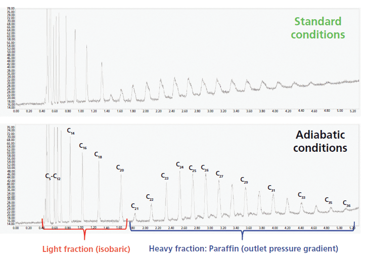
Figure 8: Simultaneous separation of the volatile (from C5 to C20) and nonvolatile (from C21 to C36) fractions of a complex sample by applying a single SFC run using either a standard (top) or the same but vacuum-jacketed column (bottom). Column: 150 mm × 3.0 mm packed with 1.8-µm fully porous HSS-SB-C18 particles; detection: flam ionization; injection volume: 0.2 µL. The separation of the most volatile compounds required extreme isobaric conditions (pure carbon dioxide, low column outlet pressure of 1500 psi, high eluent temperature 90 °C), and the elution of the heavy fraction was carried out under gradient conditions by linearly increasing the column outlet pressure from 1500 psi to 3500 psi over 5 min. The pressure gradient starts after a 2-min run.
References
(1) H.-J. Lin and Sc. Horvath, Chem. Eng. Sci. 36, 47–55 (1981).
(2) D. Poe and J. Schroden, J. Chromatogr. A 1216, 7915–7926 (2009).
(3) F. Gritti and G. Guiochon, Anal. Chem. 80, 5009–5020 (2008).
(4) F. Gritti and G. Guiochon, Anal. Chem. 80, 5009–5020 (2008).
(5) J. Kostka, F. Gritti, G. Guiochon, and K. Kaczmarski, J. Chromatogr. A 1217, 4704–4712 (2010).
(6) K. Kaczmarski, F. Gritti, J. Kostka, and G. Guiochon, J. Chromatogr. A 1216, 6575–6586 (2009).
(7) F. Gritti, M. Gilar, and J. Jarrell, J. Chromatogr. A , 1444, 86–98 (2016).
(8) F. Gritti, M. Gilar, and J. Jarrell, J. Chromatogr. A 1456, 226–234 (2016).
(9) F. Gritti, M. Fogwill, M. Gilar, and J. Jarrell, J. Chromatogr. A 1468, 217–227 (2016).
(10) F. Gritti, M. Fogwill, M. Gilar, and J. Jarrell, J. Chromatogr. A 1472, 107–116 (2016).
Fabrice Gritti is a Principal Research Scientist at Waters Corporation in Milford, Massachusetts. Direct correspondence to: Fabrice_Gritti@waters.com

New Method Explored for the Detection of CECs in Crops Irrigated with Contaminated Water
April 30th 2025This new study presents a validated QuEChERS–LC-MS/MS method for detecting eight persistent, mobile, and toxic substances in escarole, tomatoes, and tomato leaves irrigated with contaminated water.
Accelerating Monoclonal Antibody Quality Control: The Role of LC–MS in Upstream Bioprocessing
This study highlights the promising potential of LC–MS as a powerful tool for mAb quality control within the context of upstream processing.
University of Tasmania Researchers Explore Haloacetic Acid Determiniation in Water with capLC–MS
April 29th 2025Haloacetic acid detection has become important when analyzing drinking and swimming pool water. University of Tasmania researchers have begun applying capillary liquid chromatography as a means of detecting these substances.

.png&w=3840&q=75)

.png&w=3840&q=75)


.png&w=3840&q=75)


.png&w=3840&q=75)


