Autosampler Carryover
Because each sample is unique, you will need to check for carryover under the conditions of each method.
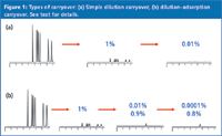
Carryover is the appearance of an analyte in a run when a blank containing no analyte is injected. This is illustrated in Figure 1(a), where a peak corresponding to 1% of the sample peak is seen with the injection of a blank. Carryover is a problem, from a quantitative standpoint, only when the carryover peak is large enough to compromise the results generated from a liquid chromatography (LC) method.
Consider the influence of 1% carryover on two common types of LC applications. First, in a potency or content uniformity assay the target analyte concentration is 100% of the label claim for a pharmaceutical product. The manufacturing tolerance might be ±2% of this value, such that all samples would be expected to fall within 98–102% of the label claim. If a tablet had a true content of 101.5%, it would still fall within the specifications, but if 1% carryover existed, the additional 1% would give an apparent concentration of 102.5%, and the sample would fail. Such an erroneous result could cause considerable expense and time spent trying to track down a manufacturing problem that in reality is attributable to the analysis, not the production process.
Nevertheless, a method for the determination of a drug in plasma generally has an allowable variation of ±15% at all levels above the lower limit of quantification (LLOQ), and ±20% at the LLOQ. If the method was being used to generate pharmacokinetic data, samples are generally run in a series, representing the drug concentration in plasma over time. Thus, each successive sample is rarely less than 20% of the concentration of the previous sample. So, if a 20% sample had an additional 1% carryover from the previous 100% sample, it would be reported as a 21% assay. This is a 5% error, which would be within the ±15% acceptance criteria, but most workers would consider this much carryover unacceptable.
So, how much carryover is acceptable? This is one of those "that depends" answers. Zero carryover is desired, but from a practical point of view, is never possible. However, most workers would find carryover greater than 0.05–0.1% unacceptable. This month's "LC Troubleshooting" instalment examines carryover — what it is, how to measure it, and some ways to reduce carryover.
Identifying Carryover
As mentioned previously, carryover is observed when a blank is injected immediately after a high concentration of the analyte. The most common type of carryover results from a tiny residue of sample that is left over from a previous injection. This is common in the injection port of some autosamplers. In the example of Figure 1(a), a sample equivalent to 1% of the previous peak remains somewhere in the autosampler after the first injection. When a blank is injected, this remaining sample is injected and a peak of 1% of the original area is generated, with the same retention time as the original sample. If a second blank injection is made, 1% of this 1% peak remains, so the second blank will have a peak area of 0.01% of the original. It can be seen that this type of carryover is insignificant by the second blank injection for nearly any application.
A second type of carryover complicates simple dilution carryover by adding adsorptive interactions to the process. In this instance, one or more of the sample components is adsorbed somewhere in the system (for example, on the injection valve rotor or the sample injection needle), but it isn't displaced as quickly as is the case with dilution. I have illustrated this in Figure 1(b), where most of the sample components (top row) show 1% carryover of the dilution type, but one component is adsorbed strongly (bottom row), so it is washed very slowly from the system. The result is 1% carryover in the first blank, 0.9% in the second (circled value), 0.8% in the third, and so forth. It is clear that this kind of adsorptive carryover is potentially much more important than dilution carryover because significant analyte concentrations can remain in the second and subsequent blanks.

Figure 1
Where Does It Come From?
The peaks attributed to carryover in LC runs generally originate from one of three sources: general laboratory contamination, sample preparation or the autosampler. A well-designed set of experiments should help you isolate the source. For example, if you fill an autosampler vial with injection solvent and inject it as the blank, you are bypassing the sample preparation process. If injection of a blank that has passed through the sample preparation process shows carryover peaks, but the injection solvent itself doesn't, there is a problem in sample preparation. Run more blanks through the sample preparation steps, but eliminate one of the steps for each sequence. Common sources of contamination are pipettors, evaporators and any other components that are reused for each batch of samples processed. Peaks in blanks that result from general laboratory contamination can be hard to isolate, but in my experience this kind of contamination generates a small, but constant peak size that does not diminish with additional injections as dilution and adsorption carryover do. The remainder of this article will consider only carryover attributable to the autosampler.
Internal Flushing
The two most popular autosampler designs in use today are shown in Figure 2. The push-to-fill design [Figure 2(a)] is an automated version of manual injection. In this design, a needle attached to a motor-driven syringe is moved to the sample vial, filled and then transfers the sample to the injection loop. The valve rotor is moved and the sample is injected. Any sample residue left inside the needle, syringe and connecting tubing can be flushed out with a wash solvent. The needle-in-loop design [Figure 2(b)] combines the needle and loop in one component, so that the needle and loop are flushed by the mobile phase during sample elution; no additional internal rinsing of the needle should be needed. Because rinsing takes place during the chromatographic run, it is best to leave the loop in the inject position during the entire run for maximum flushing, especially in gradient elution. Thus, "load-ahead" designs, in which the loop is removed from the inject position before the run is complete, have the potential for less thorough flushing of the inside of the loop. In my experience, carryover caused by poor flushing of the internal loop surfaces is not a major problem.

Figure 2
External Flushing
Carryover can also result from sample residue left on the outside of the sample needle. One possible scenario is illustrated in Figure 3, which shows the tip of the sample needle pressed against the seal, as would be the situation with the high-pressure seal in a needle-in-loop autosampler during injection. In Figure 3(a), a film of sample on the outside of the needle runs down the needle during injection, forming a droplet outside of the needle port. When the needle is removed from the port to pick up the next sample, this droplet runs down inside the needle port [Figure 3(b)] and would show up as carryover in the next injection.

Figure 3
The vial septum is the first line of defence to remove any sample residue from the outside of the needle. A well-chosen septum will act as a squeegee and wipe the outside of the needle, minimizing the amount of sample remaining. Polymeric septa, such as silicone or polytetrafluoroethylene (PTFE)-faced silicone work well in this regard. Foil or PTFE-film septa tend to tear during injection and are less efficient at wiping the needle when it is removed from the sample vial or plate.
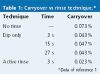
This remaining external residue must be washed off the needle before the sample is injected to avoid the type of contamination shown in Figure 3. In one study,1 chlorhexidine was used to compare external needle washing techniques. The results are summarized in Table 1. If no rinse step was used, the carryover was approximately 0.07%. One method to wash the needle is to dip it in a vial of wash solvent. In the present example, the mobile phase (55:45 10 mM phosphate buffer plus 100 mM sodium perchlorate (pH 2.6)–acetonitrile) was used as the wash solvent. The data in Table 1 show that this technique reduced the carryover by approximately half (0.04%). The amount of time the needle was dipped in the wash solvent didn't matter. This is likely because after the initial solvent contact, any additional cleaning resulted from diffusion in the nonagitated wash vial. An active rinse, in which the needle was dipped in a wash station with wash solvent flowing past the outside of the needle, reduced the carryover to approximately one third (0.02%) of the nonrinse case. The active rinse appears to be more effective than a static dip, but the static dip is a great improvement over no rinsing at all.

Table 1: Carryover vs rinse technique.*
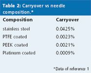
In addition to a film of sample that can remain on the outside of the needle, sample can adsorb to the needle surface, as well. The same study examined the composition of the injector needle surface in terms of adsorptive carryover, as summarized in Table 2.1 Most autosampler needles are made of one of the stainless steel alloys; this served as a reference, with approximately 0.04% carryover under the same conditions as mentioned previously (chlorhexidine sample, phosphate–perchlorate–acetonitrile wash solvent). Hydrophobic needle coatings, such as PTFE or polyetheretherketone (PEEK), reduced carryover by approximately 20-fold, but these polymeric coatings are subject to mechanical wear and have limited lifetimes. A platinum-coated needle reduced carryover by another twofold and had the added advantage of durability — it continued to provide low carryover even after 20000 injections.

Table 2: Carryover vs needle composition.*
Adsorption of samples on the internal surfaces of the autosampler is another potential source of carryover. The use of Delrin (acetal resin), Tefzel (ethylene–tetrafluoroethylene copolymer), or PEEK injector rotor seals seems to reduce problems of adsorption of hydrophobic compounds. Internal injection valve surfaces should be flushed during the separation, just as the inside of the loop is. With push-to-fill autosampler designs, it is important to ensure that all valve passages are well rinsed to minimize carryover.
The Best Rinse Solution
Every analyte is different and might require a different wash solvent to minimize carryover. Internal surfaces are generally well flushed with the mobile phase during sample elution. Other internal surfaces might need to be washed with another wash solvent. Choose a set of conditions that will be effective for the analyte you are using. This is often a combination of a high-percent organic solvent, such as 80–100% methanol or acetonitrile; many users like the solvent qualities of isopropanol for a wash solvent. Choose a pH that will solubilize the sample — generally high or low pH is all that is needed, not a true buffer. For this, I like to use a volatile acid or base to adjust the pH (for example, formic acid or ammonium hydroxide) rather than a nonvolatile salt, such as phosphate. This is because I've never seen an autosampler that doesn't leak once in a while — volatile wash solvents will evaporate, whereas nonvolatile ones leave a crusty mess to clean up. And don't forget to change the autosampler wash solvent regularly (for example, once a week) and wash or replace the wash solvent reservoir.
The Bottom Line
Because each sample is unique, you will need to check for carryover under the conditions of each method. If carryover is higher than is acceptable, track down the source of carryover, then set about correcting it. Select wash conditions and vial closures that minimize carryover. Judicious arrangement of samples in the autosampler tray can also minimize problems associated with carryover — arrange the samples from low concentrations to high or if a low concentration sample follows a high one, insert a blank between them. And remember, some autosamplers show higher carryover than others — if you are about to buy a new autosampler, carryover is an important characteristic to consider. Unfortunately, carryover is a problem that you will never be able to eliminate, but you should be able to keep it down to an acceptable level.
"LC Troubleshooting" editor John W. Dolan is vice-president of LC Resources, Walnut Creek, California, USA; and a member of the Editorial Advisory Board of LCGC Europe. Direct correspondence about this column to "LC Troubleshooting", LCGC Europe, Advanstar House, Park West, Sealand Road, Chester CH1 4RN, UK.
Readers can also direct questions to the Chromatography Forum at http://www.chromforum.com
References
1. Data supplied by Shimadzu Scientific Instruments, Columbia, Maryland, USA.
Common Challenges in Nitrosamine Analysis: An LCGC International Peer Exchange
April 15th 2025A recent roundtable discussion featuring Aloka Srinivasan of Raaha, Mayank Bhanti of the United States Pharmacopeia (USP), and Amber Burch of Purisys discussed the challenges surrounding nitrosamine analysis in pharmaceuticals.
Extracting Estrogenic Hormones Using Rotating Disk and Modified Clays
April 14th 2025University of Caldas and University of Chile researchers extracted estrogenic hormones from wastewater samples using rotating disk sorption extraction. After extraction, the concentrated analytes were measured using liquid chromatography coupled with photodiode array detection (HPLC-PDA).


